Table of Contents
Advertisement
Quick Links
Advertisement
Table of Contents

Related Manuals for Ruijie RG-AP680-A


Summary of Contents for Ruijie RG-AP680-A
- Page 1 Ruijie RG-AP680-A Access Point Hardware Installation and Reference Guide V1.0...
- Page 2 Ruijie Networks reserves all copyrights of this document. Any reproduction, excerption, backup, modification, transmission, translation or commercial use of this document or any portion of this document, in any form or by any means, without the prior written consent of Ruijie Networks is prohibited. Exemption statement The products, services or features you purchase are subject to commercial contracts and terms.
- Page 3 It is intended for the users who have some experience in installing and maintaining network hardware. At the same time, it is assumed that the users are already familiar with the related terms and concepts. Obtaining Technical Assistance Ruijie Networks Website: https://www.ruijienetworks.com/ Technical Support Website: https://ruijienetworks.com/support...
-
Page 4: Product Overview
· 1 Product Overview The RG-AP680-A, adhering to the latest 802.11ax standard, is a wireless access point (AP) designed by Ruijie for campus scenarios. Featuring two spatial streams each radio, this dual-radio and dual- band AP provides an access rate up to 575 Mbps at 2.4G and 1,200 Mbps at 5G, totaling 1.775 Gbps (2.4G+5G) or 2.4Gbps (5G+5G). -
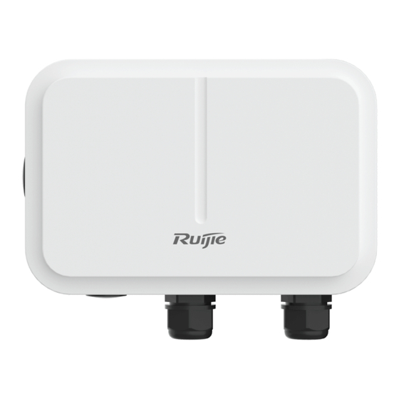
Page 5: Product Appearance
Table 1-3 Reset Button of RG-AP680-A Button State Meaning When powered Resets the AP. pressed for less than 2s Reset button When powered Restores the factory default settings. pressed for more than 3s 1.2 Product Appearance Figure 1-1 Product Appearance of the RG-AP680-A... -
Page 6: Power Supply
Hardware Installation and Reference Guide Product Overview · · 1. Condole port and reset button 3. 10/100/1000 Base-T auto-sensing Ethernet/PoE port Note: 2. Port for 48 V DC power supply 4. SFP port 1.3 Power Supply The AP supports 802.3af PoE or 44 - 57 V DC power supply. When PoE power supply is adopted, please make sure the peer end support 802.3af/802.3at, too. -
Page 7: Preparing For Installation
Hardware Installation and Reference Guide Preparing for Installation · · 2 Preparing for Installation To prevent device damage and physical injury, please read carefully the safety recommendations described in this chapter. Recommendations do not cover all possible hazardous situations. 2.1 Grounding and Lightning Protection ... -
Page 8: Temperature And Humidity
Hardware Installation and Reference Guide Preparing for Installation · 2.2.1 Temperature and Humidity · Table 2-1 Required Temperature and Humidity for the RG-AP680-A -40° C to 65° C (-40° F to 149° F) Operating Temperature Operating Humidity 0% to 100% (non-condensing) 2.2.2 Outdoor Installation... -
Page 9: Fiber Connection
Hardware Installation and Reference Guide Preparing for Installation · · 2.3 Fiber Connection Before connecting fiber cables, make sure the model of the optical transceiver and fiber type match the optical port. The transmit port on the local device should be connected to the receive port on the peer device and vice versa. 2.4 Installation Tools Table 2-2 Installation Tools Marker, Phillips (crosshead) screwdriver, slotted screwdriver, drill, paper knife, crimping pliers,... -
Page 10: Installing The Access Point
Hardware Installation and Reference Guide Installing the Access Point · · 3 Installing the Access Point Before installing the AP, make sure you have carefully read the requirements described in Chapter 2. 3.1 Installation Flowchart 3.2 Before You Begin Before you install the AP, verify that all the parts in the package contents are there and make sure that: ... -
Page 11: Installing The Ap
3.3 Precautions RG-AP680-A can be mounted on a ceiling tile or a horizontal pole (diameter: 50 mm to 140 mm, thickness: ≥2.5 mm). Otherwise, the AP could fall down and cause injuries. The installation site can vary due to on-the-spot surveys conducted by technical personnel. - Page 12 Hardware Installation and Reference Guide Installing the Access Point · · Pole Mounting Use four M5 screws to secure the AP to the mounting plate. Figure 3-1 Securing the AP with M5 Screws Attach the mounting bracket to a pole by threading two clamps through the mounting bracket. Keep the side marked by TOP on top.
- Page 13 Hardware Installation and Reference Guide Installing the Access Point · · Figure 3-3 Horizontal Pole Mounting Position the mounting plate on the mounting bracket with its two holes aligned to the screw holes on the mounting bracket. Figure 3-4 Position the Mounting Plate on the Mounting Bracket...
- Page 14 Hardware Installation and Reference Guide Installing the Access Point · · Use two M8 screws to secure the mounting plate to the mounting bracket. Figure 3-5 Securing the Mounting Plate with M8 Screws...
- Page 15 Hardware Installation and Reference Guide Installing the Access Point · Ceiling Mounting · Secure the mounting bracket on the ceiling tile using four M6 expansion bolts. Figure 3-6 Securing the Mounting Bracket Loosen the two M6 screws on the mounting plate. Rotate the plate by 90 degrees until it is upright. Tighten the M6 screws again.
-
Page 16: Connecting Cables
Hardware Installation and Reference Guide Installing the Access Point · · Complete the installation. Figure 3-9 Mounting the AP on the Ceiling Tile Please select proper screws according to the screw holes and fasten the screws securely. Please make sure that all screws are used for securing the components. Otherwise, the device may fall off. Please check whether the screws are tightened after the device is installed. - Page 17 Hardware Installation and Reference Guide Installing the Access Point · Connecting the grounding cable · The grounding cable is made on site. Connect the supplied grounding wire (yellow-green) to the AP grounding hole on one end and ground the wire on the other end through OT terminals. To avoid waste, adjust the cable length for actual demands.
- Page 18 Hardware Installation and Reference Guide Installing the Access Point · · Make sure the plug is correctly inserted. The plug can be damaged if the watertight adapter is improperly tightened. Before removing the network cable, dismantle the watertight adapter first and then the plug. Connecting the fiber-optic cable (Optional) If the diameter of LC-LC fiber is not 2.7±0.2mm, waterproofness of the adapter cannot be guaranteed.
-
Page 19: Bundling Cables
Hardware Installation and Reference Guide Installing the Access Point · · 3.6 Bundling Cables The power cables and other cables should be bundled in a visually pleasing way. When you bundle twisted pairs, make sure that the pairs at the connectors have natural bends or bends of large radius. - Page 20 Hardware Installation and Reference Guide Installing the Access Point · Before bundling cables, correctly mark labels and stick the labels to cables where appropriate. · Cables should be neatly and properly bundled, as shown in Figure 3-16. Figure 3-16 Bundling Cables ...
-
Page 21: Appendix A Connectors And Media
Hardware Installation and Reference Guide Appendix A Connectors and Media · · Appendix A Connectors and Media 1000BASE-T/100BASE-TX/10BASE-T The 1000BASE-T/100BASE-TX/10BASE-T is a 10/100/1000 Mbps auto-negotiation port that supports auto MDI/MDIX. Compliant with IEEE 802.3ab, 1000BASE-T requires Category 5e 100-ohm UTP or STP (STP is recommended) with a maximum distance of 100 meters (328 feet). - Page 22 Hardware Installation and Reference Guide Appendix A Connectors and Media · Fiber Connection · You can choose to use single mode or multimode fibers according to the transceiver module types. Figure A-4 shows connection of fiber cables. Figure A-4 Fiber Connection...
-
Page 23: Appendix B Mini-Gbic Module Specifications
· Appendix B Mini-GBIC Module Specifications Ruijie provides various Gigabit SFP transceivers (Mini-GBIC modules) for interfaces of wireless access controllers. You can select the most suitable SFP modules as needed. This appendix describes the models and specifications of some of the Gigabit SFP transceivers for your reference. -
Page 24: Appendix C Cabling Recommendations
Power cords should be routed upward or downward beside the cabinet close to the location of the DC power distribution cabinet, AC power outlet, or lightning protection box. Figure C-1 Bundling Cables of RG-AP680-A Required Minimum Cable Bend Radius ... - Page 25 Hardware Installation and Reference Guide Appendix C Cabling Recommendations · · Route and bundle power, signal, ground cables separately. When the cables are close to each other, cross them. When power cables run parallel to signal cables, the distance between them must be greater than 30 mm. ...
- Page 26 Hardware Installation and Reference Guide Appendix C Cabling Recommendations · · Wrap up unnecessary or excess cables and bind them to the appropriate rack position, where device operation is not affected and no damages occur to the device and cables during debugging. ...
- Page 27 Hardware Installation and Reference Guide Appendix C Cabling Recommendations · Diameter of Cable Bundle Space between Bundles · 10 mm 80 mm to 150 mm 10 mm to 30 mm 150 mm to 200 mm 30 mm 200 mm to 300 mm ...
-
Page 28: Appendix D Package Contents
Hardware Installation and Reference Guide Appendix D Package Contents · · Appendix D Package Contents RG-AP680-A Package Contents Item Quantity Remark Access Point Mounting Plate Mounting Bracket M5 Screws M8 Screws M6*40 Expansion Bolts Pole Clamps Applicable to the ETH/PoE port and the Watertight Adapters ports adopting DC power supply.
Need help?
Do you have a question about the RG-AP680-A and is the answer not in the manual?
Questions and answers