
Related Manuals for ITech IT6322A


Summary of Contents for ITech IT6322A
-
Page 1: Dc Power Supply
Triple Output Programmable DC Power Supply Series IT6300A/B User’s Manual Model: IT6322A/IT6332A/IT6333A IT6322B/IT6332B/IT6333B Version: V2.1... - Page 2 Notices Warranty Safety Notices © Itech Electronics, Co., Ltd. 2017 The materials contained in this No part of this manual may be document are provided “as is”, and reproduced in any form or by any means (including electronic storage is subject to change, without prior retrieval or translation into a foreign notice, in future editions.
-
Page 3: Warranty
Warranty ITECH warrants that the product will be free from defects in material and workmanship under normal use for a period of one (1) year from the date of delivery (except those described in the Limitation of Warranty below). -
Page 4: Safety Precautions
Failure to comply with these precautions or specific warnings elsewhere in this manual will constitute a default under safety standards of design, manufacture and intended use of the instrument. ITECH assumes no liability for the customer’s failure to comply with these precautions. ... -
Page 5: Environmental Conditions
The expected useful life of the product is 10 years. The product can be used safely during the 10-year Environment Friendly Use Period (EFUP). Upon expiration of the EFUP, the product must be immediately recycled. Copyright © Itech Electronics Co., Ltd. -
Page 6: Waste Electrical And Electronic Equiment (Weee) Directive
With reference to the equipment classifications described in the Annex 1 of the WEEE Directive, this instrument is classified as a “Monitoring and Control Instrument”. To return this unwanted instrument, contact your nearest ITECH office. Copyright © Itech Electronics Co., Ltd. -
Page 7: Compliance Information
Connection of the instrument to a test object may produce radiations beyond the specified limit. Use high-performance shielded interface cable to ensure conformity with the EMC standards listed above. Safety Standard IEC 61010-1:2010/ EN 61010-1:2010 Copyright © Itech Electronics Co., Ltd. -
Page 8: Table Of Contents
Technical Specifications ......................... 24 4.1 Major technical parameters .......................... 24 Chapter5 Communication with PC ......................... 28 5.1 RS232 interface ............................. 28 5.2 USB interface ..............................29 5.3 GPIB interface ............................... 30 Appendix ................................31 Copyright © Itech Electronics Co., Ltd. viii... - Page 9 IT6300A/B User’s Manual Specifications of Red and Black Test Lines ......................31 Copyright © Itech Electronics Co., Ltd.
-
Page 10: Chapter1 Acceptance And Installation
The instrument should be installed at well-ventilated and rational-sized space. Please select appropriate space for installation based on the power supply size. (W:width H:height IT6322A/IT6322B: 214.5mmW*88.2mmH*345mmD D:depth) IT6332A/IT6333A/IT6332B/IT6333B: 214.7mmW*88.2mmH*444.5mmD Refer to the dimension below: Copyright © Itech Electronics Co., Ltd. - Page 11 Acceptance and Installation Front view for IT6322A/IT6332A/IT6333A/IT6322B/IT6332B/IT6333B. Lateral view for IT6332A/IT6333A/IT6332B/IT6333B. Unit: millimeter (mm) IT6322A Model Dimension: Width: 255mm Height: 108.7mm Depth:374.32 Detailed Dimension Drawing Copyright © Itech Electronics Co., Ltd.
- Page 12 Acceptance and Installation IT6322B Model Copyright © Itech Electronics Co., Ltd.
-
Page 13: Adjustment Of Power Handle
Width: 255mm Height: 108.7mm Depth:365.7mm Detailed Dimension Drawing 1.3 Adjustment of power handle To adjust the position, grasp the handle by the sides and pull outward. Then rotate the handle to the desired position. Copyright © Itech Electronics Co., Ltd. -
Page 14: Connecting The Power Cord
If the power cord included in the instrument you purchased does not match the voltage, contact the dealer or manufacturer for change. China United States & Europe England Canada & Japan IT-E171 IT-E173 IT-E174 IT-E172 Copyright © Itech Electronics Co., Ltd. -
Page 15: Chapter2 Quick Start
Can adjust the voltage or current by knob. Can adjust the stepping by Left/right arrow button. Output timer function (0.1 ~ 99999.9 seconds) Model Selection Table for IT6300A/B Series: Model Channel Voltage Current IT6322A Copyright © Itech Electronics Co., Ltd. -
Page 16: Introduction To The Front Panel
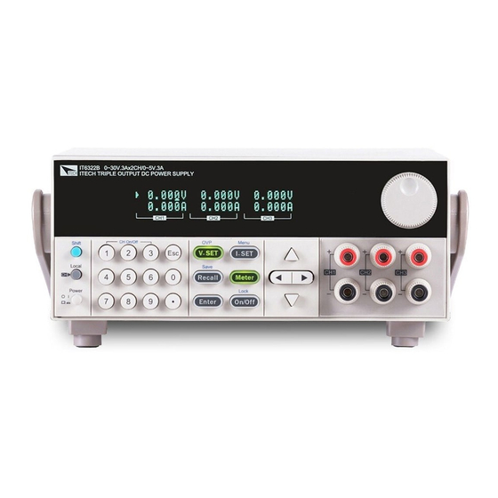
IT6332A IT6333A IT6322B IT6332B IT6333B *IT6322A/IT6332A/IT6333A has not standard GPIB communication interface. 2.2 Introduction to the front panel The front panel of IT6300A/B series is shown in the next figure. VFD display Rotary knob Power switch, Local and Shift key... - Page 17 Right/Left key, use to move the cursor or scroll through the menu items. Up/down key, used to increase or decrease the setting value. Used to turn on the output of corresponding channel no matter in (Shift)+1, menu operation or Meter state. (Shift)+2, (Shift)+3 Copyright © Itech Electronics Co., Ltd.
-
Page 18: Introduction Of Indicators On The Screen
Indicates the channel currently selected. Enable tracking mode. 2.5 Introduction to the rear panel The rear panel of IT6322B/IT6332B/IT6333B is shown in the next figure. The rear panel of IT6322A/IT6332A/IT6333A is shown in the next figure. Cooling window RS232 communication interface USB communication interface... -
Page 19: Power-On Selftest
If send channel data, the channel response failure, the VFD display the tooltip information “Model Fail”. If calibration data read failure, the VFD display the tooltip information “Cal Lost”. If the channel to send data loss, channel initialization failed, the VFD Copyright © Itech Electronics Co., Ltd. - Page 20 Specification (110VAC) IT6322A/ IT6322B 3.15A T250V 6.30A T250V IT6332A/ IT6332B 5A T250V 10A T250V IT6333A/ IT6333B 5A T250V 10A T250V 3) After replacement, install the fuse box back to original position, as shown below. ----End Copyright © Itech Electronics Co., Ltd.
-
Page 21: Output Verification
Make sure that the current can be adjusted from 0 to full rated value. Disable the output and then remove the short wire. Check the other two channels by the same method. ----End Copyright © Itech Electronics Co., Ltd. -
Page 22: Chapter3 Function And Features
When V-SET/I-SET buttons are lit, following conditions will enable the cursor to display again. Pressing V-SET/I-SET buttons again. Adjusting the knob. Pressing direction buttons. Copyright © Itech Electronics Co., Ltd. -
Page 23: Menu Description
Reset default Keep Restore the last time parameters Knob Knob Function Set Pulsating knob function Settings Unlock Pulsating knob function open Lock Pulsating knob function closed Buzzer Power Key Beeper Set Key sound establishment Copyright © Itech Electronics Co., Ltd. - Page 24 5s. Reset Reset Menu Default restore the factory setting Cancel Enter Exit Exit the config menu System System Menu Channel Sel … Channel Select System Menu… Max volt Max voltage Set Max Volt=31.000V Copyright © Itech Electronics Co., Ltd.
- Page 25 This parameter sets the output On/Off state at power up. If you select “Keep”, the power supply will save the output state prior to power down and revert to that state at power up. If you select “Off”, the output state is always Copyright © Itech Electronics Co., Ltd.
- Page 26 This item enable(“Wait5Sec”) or disable(OFF) the function to turn back to meter state automatically. When select “Wait5Sec”,the display on front panel will automatically change to meter state under the condition of no operation within 5S. Copyright © Itech Electronics Co., Ltd.
- Page 27 Front display as follows in condition of output off and meter state. Parallel (Parallel mode) This function configures the instrument for parallel operations of three channels. Possible combination mode are CH1+CH2,CH2+CH3,ALL. Enter Press button to confirm your set.And press to quit the operation. Copyright © Itech Electronics Co., Ltd.
- Page 28 Operate “CH1+CH2” in parallel, the max voltage is the smallest max voltage of the two channels. It is 31V. Operate “CH2+CH3” in parallel, the max voltage is the smallest max voltage of the two channels, it is 6V. Copyright © Itech Electronics Co., Ltd.
-
Page 29: Channel Operation
(Shift)+ (Shift)+ (Shift)+ corresponding to each channel. (Shift)+ controls the output state of the first channel, (Shift)+ controls the output state of the second channel, (Shift)+ controls the output state of the third channel. Copyright © Itech Electronics Co., Ltd. -
Page 30: Timer Operation
Enter to exit. I-set I-set Solution 3: Press , then press to move the cursor position and adjust the current value using . Press Enter to exit. Copyright © Itech Electronics Co., Ltd. -
Page 31: Save And Recall Operation
If the internal temperature of the power supply exceeds 80℃,the instrument will protect itself by automatically turning power OFF. When this happens you will hear a buzzer and the display will indicate the following: Over Temperature… Copyright © Itech Electronics Co., Ltd. -
Page 32: Remote Sense Function
Connect output “+” and “-“(front panel) to the load input terminals “+” and “-“. Connect “S+” to “+” of the load, ”S-“ to the “-“ of the load. NOTE To ensure the system stability, please use twisted-pair cables between sense terminal and load. Copyright © Itech Electronics Co., Ltd. -
Page 33: Chapter4 Technical Specifications
(%of output + offset) Current ≤0.02%+5mV Voltage Parallel setup accuracy ≤0.1%+20mA Current Memory Save/recall 36 groups Function Output timer Timer Time set 0.1~99999.9 second Resolution 0.1 second Working temperature 0-40℃ Dimension (mm) W×H×D 214.5mm×88.2mm×354.6mm Copyright © Itech Electronics Co., Ltd. - Page 34 (%of output + offset) ≤0.02%+5mV Voltage Parallel setup accuracy ≤0.1%+30mA Current Memory Save/recall 36 groups Function Output timer Timer Time set 0.1-99999.9 second Resolution 0.1 second Working temperature 0-40℃ Dimension (mm) W×H×D 214.5mm×88.2mm×453.1mm Weight (net) 15Kg Copyright © Itech Electronics Co., Ltd.
- Page 35 Voltage 100-120V 10mV Series setup resolution Current 0-99V Voltage Series Read-back 100-120V 10mV resolution Current ≤0.02%+10mV Voltage Parallel setup accuracy ≤0.1%+30mA Current Memory Save/recall 36 groups Function Output timer Timer Time set 0.1-99999.9 second Copyright © Itech Electronics Co., Ltd.
- Page 36 Technical Specifications Resolution 0.1 second Working temperature 0-40℃ Dimension (mm) W×H×D 214.5mm×88.2mm×453.1mm Weight (net) 15Kg *The above specifications may be subject to change without prior notice. Copyright © Itech Electronics Co., Ltd.
-
Page 37: Chapter5 Communication With Pc
Chapter5 Communication with PC IT6322B/IT6332B/IT6333B Standard configuration have three communication interface: RS232 , USB and GPIB, IT6322A/IT6332A/IT6333A Standard configuration have two communication interface: RS232 and USB. The user can choose any one to realize the communication with the computer. The following content can help you understanding how to through the computer control power supply output. -
Page 38: Usb Interface
You can connect the power and computer by using a USB cable with an A type port and a B type port. All the power function can programmed through the USB. The power supply USB488 interface functions are described as follows: Interface is 488.2 USB488 interface. Copyright © Itech Electronics Co., Ltd. -
Page 39: Gpib Interface
0 ~ 31.You can Enter the I-set I-set system menu functions by pressing (Shift)+ (Menu). You can find GPIB address settings through pressing and Input address, then Enter press to confirm. GPIB address is stored in nonvolatile line storage. Copyright © Itech Electronics Co., Ltd. -
Page 40: Appendix
Specifications of Red and Black Test Lines ITECH provides you with optional red and black test lines, which individual sales and you can select for test. For specifications of ITECH test lines and maximum current values, refer to the table below. - Page 41 Contact Us Thanks for purchasing ITECH products. In case of any doubts, please contact us as follows: 1. Refer to accompanying data disk and relevant manual. 2. Visit ITECH website:www.itechate.com 3. Select the most convenient contact method, for further information.
Need help?
Do you have a question about the IT6322A and is the answer not in the manual?
Questions and answers