
Subscribe to Our Youtube Channel
Related Manuals for ITech IT6302


Summary of Contents for ITech IT6302
- Page 1 IT6302 user manual USER MANUAL Triple Output Programmable DC Power Supply Model IT6302 © Copyright belongs to ITECH Co. ltd. Ver2.4/Sep. 2019/ IT6300-508 USER MANUAL...
-
Page 2: Table Of Contents
IT6302 user manual Security regulation ............................3 Safety symbols ..............................3 Certification and Quality Assurance ........................ 3 Introduction ................................ 4 Chapter 1 Quick Reference ..........................5 1.1 The front panel and rear panel description ................... 5 1.1.1 Front panel ............................5 1.1.2 The Rear Panel .......................... -
Page 3: Security Regulation
The symbol on an instrument indicates that the user should refer to the operating instructions located in the manual. High voltage danger Certification and Quality Assurance IT6302 programmable DC power supply fully meets all of the technical specification in the manual. Warranty USER MANUAL... -
Page 4: Introduction
If the content of this manual is subject to change, we will not notice additionally Introduction IT6302 triple output programmable DC power supply,the output voltage or current of each channel can be set from 0 to max rated value. The triple output power supply provides you with high-resolution, high accuracy and high stability, and supports over voltage, over temperature protection;... -
Page 5: Chapter 1 Quick Reference
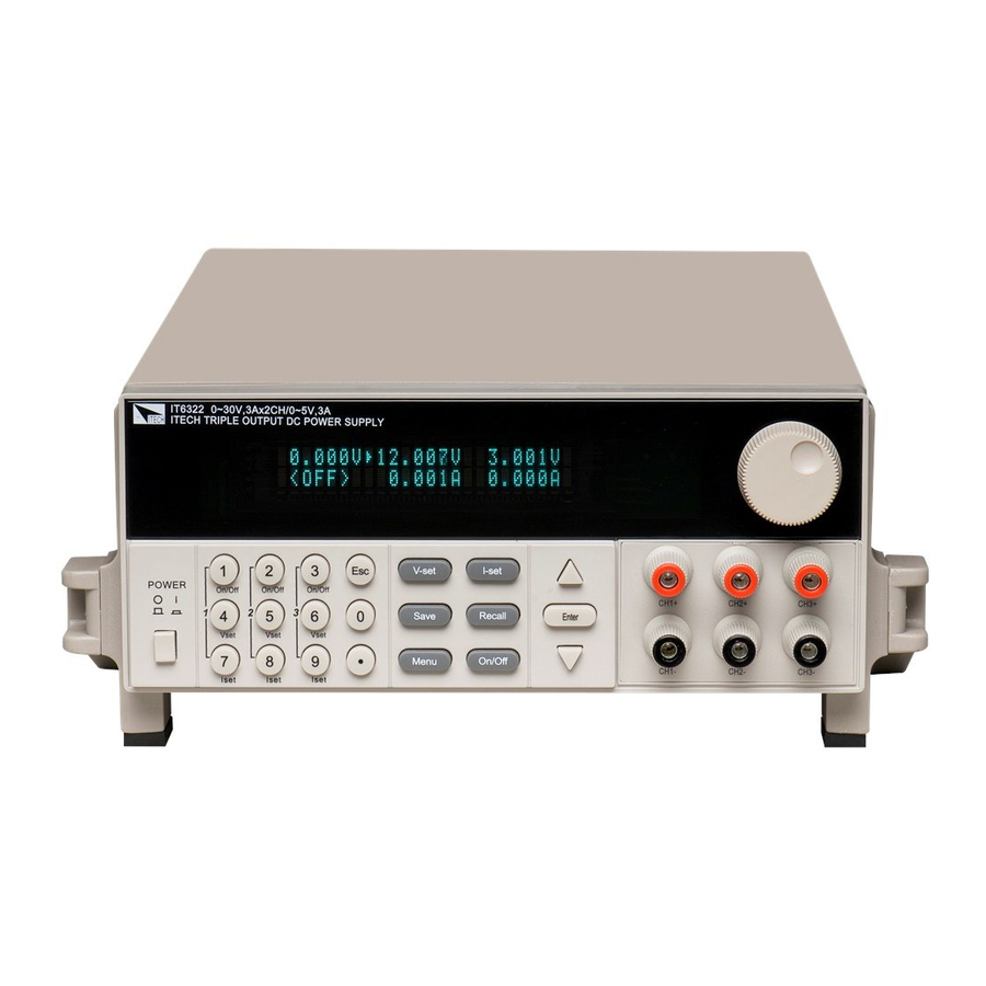
IT6302 user manual ⚫ The voltage and current for the three channels can be displayed at the same time ⚫ Small size of 1/2 2U ⚫ VFD display ⚫ Function keys with LED light ⚫ High accuracy , resolution and stability ⚫... - Page 6 IT6302 user manual Picture 1 VFD display Rotary knob Power switch, Local and Shift key Numeric keys and ESC escape key Function keys Up/Down/Left/Right keys Output terminal VFD display description The status flags will be described in chapter 3.3. Output terminal...
-
Page 7: The Rear Panel
IT6302 user manual Note: If the power supply is used to charge the battery, you should pay attention to the positive and negative polarity; otherwise you may burn the power supply! 1.1.2 The Rear Panel Picture 2 Ventilation holes 110V/220V AC power selection switch... -
Page 8: Dimensions
IT6302 user manual 1.1.3 Dimensions The dimension of IT6302 power supply: Unit: millimeter (mm) 1.2 Preliminary Checkout The following steps help you verify that the power supply is ready for use. 1.2.1 Check the list of supplied items Verify that you have received the following items with your power supply, if anything is missing, contact your authorized supplier. -
Page 9: Checkout Procedure
IT6302 user manual Warning: The power supply provides a three-wire power cord; you should plug it to a three cord junction box. You should also make sure the power supply is well grounded. Warning: The connection wire should have enough current capacity that it can bear the max rated current/short current of the power supply and not get too hot. -
Page 10: Output Verification
IT6302 user manual If the latest operation state of the power supply was lost, then the VFD will display (about 2S): Syst Lost Picture 6 During channel scan, the VFD will display: Scan Chan Picture 7 When checkout for one channel is failed, then the VFD will display (about 2S):... -
Page 11: If The Power Supply Does Not Turn On
IT6302 user manual ◼ Current output Check The following steps check the basic current functionality by shorting the power supply’s output. 1) Press Power key to turn on the power supply On/Off 2) Press to disable the output, ensure the output is OFF. -
Page 12: Adjust The Carrying Handle
IT6302 user manual Use the same specification of fuse to replace the old one, install it to the fuse box and then insert. 1.2.7 Adjust the carrying handle To adjust the position, grasp the handle by the sides and pull outward. Then rotate the handle to the desired position. - Page 13 IT6302 user manual IT6302 Parameters Voltage 0-30V×2, 0-5V×1 Rated values Current 0-3A×2, 0-3A×1 (0 ° C - 40 ° C) Power CH1:90W,CH2:90W,CH3:15W ≤0.01%+4mV Voltage Load regulation ≤0.2%+3mA (%of output + offset) Current ≤0.01%+4mV Line regulation Voltage ≤0.2%+3mA (%of output + offset)
-
Page 14: Additional Features
IT6302 user manual ≤0.01%+10mV Voltage Setup stability-8h ≤0.1%+5mA (%of Output +Offset) Current ≤0.01%+20mV Voltage Readback stability-8h ≤0.1%+5mA (%of Output +Offset) Current Fuse specification 6.3A(110V)/3.15A(220V) Command Response (Typical) 20mS Time Power Factor 0.7 (Typical) Maximum input current 4.5A(110V)/2.2A(220V) Maximum input 700VA... -
Page 15: Chapter 3 Front-Panel Operation
IT6302 user manual Chapter 3 Front-panel Operation So far we have covered the quick start chapter which briefly introduced the front panel operation and how to check basic voltage and current functionality. This chapter describes in detail how to operate the instrument manually via the front-panel keys. -
Page 16: Panel Description
IT6302 user manual Note: If there is any operation on front panel within 5S, the cursor will disappear automatically. You can also disable the cursor by pressing ESC button. When VFD displays cursor, you can modify the parameters by adjusting knob or up/down keys, or move the cursor by right/left keys. -
Page 17: Vfd Description
IT6302 user manual I-set I-set /Menu Use to set the current or shift+I-set to enter the menu operation. Recall /Save Save or recall different operating parameters in memory locations Switch the display between setting value and actual value Enter /Lock... -
Page 18: Panel Operation
IT6302 user manual to the previous menu.When the item keeps filickering indicates it is selected currently. Note: Both pressing Enter and down arrow key can display the next menu. But the difference between the two methods is as follows: press enter key can save the current setup, while press up/down key will not change the previous setup. -
Page 19: Current Operation
IT6302 user manual V-set V-set Solution 3: Press ,then press to move the cursor position and adjust the Enter voltage value using . Press to exit. Note: When output in OFF mode and button is dark, rotary knob and up/down keys cannot be used to adjust voltage and current. -
Page 20: Lvp Operation
Picture 13 Over Voltage Protection (OVP) IT6302 has over voltage protection function at power on.OVP function may be triggered because of internal error, customer’s wrong operation or too higher external voltage. Once the power supply is protected, will the user hear a buzzer and output will be turned off, meanwhile corresponding channel will display OVP in voltage value position and current value position will display”... - Page 21 IT6302 user manual at power on. “remember” output On/Off state Last before power off Beep Disable buzzer Enable buzzer BAUD Baudrate 4800 Baudrate 9600 38.4 Baudrate 38400 Grp1 Save to group1 Grp2 Save to group2 Grp3 Save to group3 COUP Configure connection mode between CH1&CH2...
- Page 22 This parameter configures the connection mode of CH1 and CH2.Corresponding setup in the menu includes Off, Ser, Par. IT6302 only supports to set Serial/Parallel mode for CH1 and CH2 in menu operation. When set Serial/Parallel mode, VFD will have corresponding symbols at the position of CH2.In this mode, user only need to set the total current on one channel, the power supply...
- Page 23 IT6302 user manual system will quit menu after 2s. For example, in output off state and Meter selected mode, VFD displays as follows: Picture 14 Wiring in serial mode: Par (Parallel mode) This parameter configures connection mode of CH1 and CH2 to parallel mode in menu operation.
- Page 24 After connect in series/parallel, save and recall function are forbidden. When select series or parallel connection, hardware connection is needed. TRAC (sync output setting) The TRACK function of IT6302 could change voltage/current of CH1, CH2 in scale. When select it, CH1 and CH2 could be set as synchronous mode; choose “On”...
- Page 25 , VFD will display power information; the information includes the following parts: Power Model Display the model of power supply: IT6302 Soft Version Software version of power supply: 1.XX Press left-right key or conversion knob, will display the following information:...
-
Page 26: Communication Module Introduction
PC 4.1 Communication module introduction The DB9 interface connector on the rear panel of IT6302 power supply is TTL level, and you need to use level converter to connect PC series port. Notice: please don’t connect IT6302 with standard RS232 cable. It may damage the power supply. -
Page 27: Communication Between Power Supply And Pc
Using a Level converter circuit connect DB9 interface connector of IT6302 and RS232/USB interface connector of PC to do communication. Below will helps you to have the knowledge of controlling IT6302 power supply via PC. 1. Communication setting Before communicate, please set the following parameters of power supply and PC to make them match with each other. - Page 28 If you have a problem, follow these steps: 1 Check the documentation that come with the product 2 Visit the ITECH online service Web site is www.itechate.com ,ITECH is available to all ITECH customers. It is the fastest source for up-to-date product information and expert...
Need help?
Do you have a question about the IT6302 and is the answer not in the manual?
Questions and answers