
Related Manuals for ITech IT6322


Summary of Contents for ITech IT6322
- Page 1 USER’S GUIDE Programmable DC Power Supply Model IT6322 Copyright 2009 All Rights Reserved Ver2.0/Oct, 2009/ IT6300-508...
-
Page 2: Table Of Contents
I n t r o d u c t i o n ················································································· Chapter1 Quick Start 1.1 Front Panel & Rear Panel ···················································································· 1.2 Preliminary Checkout ···················································································· 1. Check the list of supplied items ··································································· 2. Connect the power cord and turn on the power supply ·································... - Page 3 IT6322 Programmable DC Power Supplies General information The following safety precautions should be observed before using this product and any associated instrumentations. Although some instruments and accessories would be used with non-hazardous voltages, there are situations where hazardous conditions may be present.
-
Page 4: About Your Safety
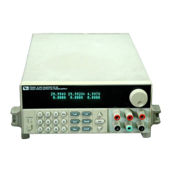
Failure to comply with these precautions or with specific warnings elsewhere in this manual violates safety standards of design, manufacture, and intended use of the instrument. ITECH assumes no liability for the customer’s failure to comply with these requirements. - Page 5 Introduction IT6300 3 channels power supply has high accuracy and high stability, also has the function of the limit voltage, over current and over temperature protection. You can set the voltage and value of from 0V to the max value in every channel. This series power supply can be connected in series and in parallel connection, it could improve the output ability of the voltage and the current value to twice.
-
Page 6: Chapter1 Quick Start
Chapter 1 Quick Start Chapter 1 Quick Start One of the first things you will do with your power supply is to become acquainted with the front panel. The exercises in this chapter prepare the power supply for use and help you get familiar with some of its front- panel operations. -
Page 7: Preliminary Checkout
Chapter1 Quick Reference 1.2 Preliminary Checkout The following steps help you verify that the power supply is ready for use. 1. Check the list of supplied items Verify that you have received the following items with your power supply. If anything is missing, contact your nearest Sales Office. -
Page 8: Output Checkout
Chapter 1 Quick Start If the calibration data in EEPROM was error Lost Factory Calibration or tthe information calibrated by factory was lost, the VFD will display as follows: 0.000V 0.000V 0 .000V <OFF> <OFF> <OFF> VFD displays: the first row is output voltage, the second row is the state when the power supply is on or current. -
Page 9: If Power Supply Does Not Turn On
Chapter1 Quick Reference ■ Current Output Current The following steps check basic current functions with a short across the power supply’s output. Turn on the power supply. Disable the output. Press key to ensure that the output is disabled. The ON annunciator Out On/Off is turned off. -
Page 10: To Adjust The Carrying Handle
If the fuse was damaged, please see the table below to replace the fuse for your power supply. Model Fuse Description IT6322 Fuse 3.15A T250V(220V AC) Fuse 6.30A T250V(110V AC) 6. To Adjust the Carrying Handle To adjust the position, grasp the handle by the sides and pull outward. Then, rotate the handle to the desired position. -
Page 11: To Rack Mount The Instrument
Chapter1 Quick Reference 7. To Rack Mount the Instrument You can mount the power supply in a standard 19-inch rack cabinet using the IT-E151 rack mount kit. Remove the carrying handle and the two plastic ears before rack-mounting the Note: instrument. -
Page 12: Chapter 2 Specifications
Chapter 2 Specifications Chapter 2 Specifications 2.1 Specifications Paramete IT6322 Voltage 0~30V×2, 0~5V×1 Output ratings Current 0~3A×2, 0~3A×1 ( 0 °C - 40 °C) 0~31V×2, 0~6V×1 Voltage ≤0.01%+3mV The model of remote sense ±(%of output+offset) Current ≤0.01%+3mA Voltage ≤0.01%+3mV Line Regulation ±(%of output+offset) -
Page 13: Supplemental Characteristics
AC Input Ratings (selectable via switch on the rear panel) Option Opt.01: 220AV±10%, 47 - 63HZ Option Opt.02: 110AV±10%, 47 - 63HZ Maximum input power Model Power IT6322 750VA Cooling Fan cooled Operating Temperature 0 to 40 °C for full rated output Storage Temperature -20 to 70 °C for storage environment. -
Page 14: Chapter 3 Front-Panel Operation
Chapter 3 Front-panel Operation I n t r o d u c t i o n Chapter 3 Front-panel Operation So far you have learned how to install your power supply and do quick start. During the quick start, you were briefly introduced to operating from the front panel as you learned how to check basic voltage and current functions. -
Page 15: Panel Description
Chapter 3 Front-panel Operation 3.2 Panel Description V-set V-set I-set I-set Save Recall Enter On/Off Menu ● Number key(1~3key can control the output state of 3channels, 4~6key can set voltage value for the channel, 7~9 can set current value for the channel.) Set voltage value V-set... -
Page 16: Vfd Description And Wiring Diagram
Chapter 3 Front-panel Operation 3.3 VFD Description and Wiring Diagram There are some sighs on the VFD when the power supply is on, which denotes different meaning The output is off. The key panel is locked. The power supply is in remote mode. There is some error or fault with the power supply. -
Page 17: Panel Operation
Chapter 3 Front-panel Operation Exit System Set… Out Series Set Set series connection Out Parallel Set Set parallel connection Max Voltage Set… Set max voltage for each channel Set First Channel Set Second Channel Set Third Channel Out Time Set… Set output time for each channel Set First Channel Set Second Channel... -
Page 18: Setting Voltage
Chapter 3 Front-panel Operation When the power supply is in panel operation, you can press to control the output state of all channels. Or you can press one number key( )to control one channel’ output state. Key controls the output state of the first channel, key controls the output state of the second channel, key controls the output state of the third channel. -
Page 19: Setting Current
Chapter 3 Front-panel Operation When the knob function is disabled: Solution 1: Press +numeric key to set voltage value, press to change V-set the value slightly, press to confirm. Enter Solution 2: Press one number key which can control channel’s voltage setting (pressing number key can control the first channel, pressing number can control the second channel and pressing number key... -
Page 20: Menu Function
Chapter 3 Front-panel Operation ■ Saving and Recalling Operation You can store up to 50 different output states in storage register locations (1 to 9). Each output state includes Constant voltage value, Constant current value and Maximum output voltage value, voltage step value. Press +number key, and save voltage and current Save value into register. - Page 21 Chapter 3 Front-panel Operation Reset Config If you enter into this menu and select “YES”, all of parameter will be as default setting. Out Parameter Set This function can decide to save the parameter or not. If you select “Last Set”, the power supply will save the output parameter for the last time when it is turned off, and when it is turned on next time, the output parameter is as the same as saved before.
-
Page 22: System Set
Chapter 3 Front-panel Operation Local Address This instruction can set the communication address for each power supply. The address range is from 0 to 31. Before the communication, you must make sure that there is same address between the power supply and the computer. Key Lock Set This instruction can set a password (1 through 4 digits) to lock the function keys operation. -
Page 23: Power Information
Chapter 3 Front-panel Operation Out Parallel Set This function can set parallel connection. No means that the power supply is not in parallel connection, 1+2 means that channel 1 and channel 2 are in parallel connection, 1+3 means that channel1 and channel 3 are in parallel connection, 2+3 means that channel 2 and channel 3 are in parallel connection. - Page 24 Chapter 3 Front-panel Operation Soft Version: the version number of power supply For example: Soft Version=1.00 Cal information: calibration information of power supply For example: 2005-8-26 17:46:13 Error Information: error information of power supply For example: 0, No Error Exit Menu after the error information has been displayed, you can Note: Enter...
-
Page 25: Chapter 4 Remote Operation Mode
Chapter 4 Remote Operation Mode Chapter 4 Remote Operation Mode The DB9 interface connector on the rear panel of the power supply can be transferred to RS-232 interface, the following information will tell you how to use the computer to control the output of the power supply. 4.1 Communication cable IT-E131 RS232 Communication cable The DB9 interface connector on the rear panel of power supply is TTL voltage level;... -
Page 26: Communication Between Power Supply And Pc
Chapter 4 Remote Operation Mode IT-E131 communication cable IT-E132 communication cable Power Power Load supply supply IT-E131 ISOLATED IT-E131 ISOLATED COMMUNICATION CABLE COMMUNICATION CABLE RS232 RS232 ISOLATION ISOLATION TTL(5V) TTL(5V) 859666668889942311 859666668889942311 IT-E135 GPIB Communication Cable The DB9 interface connector on the rear panel of power supply is TTL voltage level; you can use the GPIB communication cable (IT-E135) to connect the DB9 interface connector of the power supply, and then connect the GPIB interface of the IT-E135 and computer with GPIB/ IEEE 488 line for the communication. - Page 27 Chapter 4 Remote Operation Mode 4.2 Communication between Power Supply and PC Before using the remote operation mode, please make sure that the baud rate and communication address in power supply are the same as in the computer software, otherwise, the communication will fail, you can change the baud rate and communication address from the front panel or from computer.
- Page 28 ITECH Electronic Co.,Ltd China Tel : 025-52415098 Tel : 714-9219095 Fax: 025-52415268 Fax: 714-9216422 3 1 0 # N i n g N a n D a D a o , 22820 Savi Ranch Parkway NanJing City, 210012, Jiangsu Yorba Linda, CA 92887 U.S.A.
Need help?
Do you have a question about the IT6322 and is the answer not in the manual?
Questions and answers