Table of Contents
Advertisement
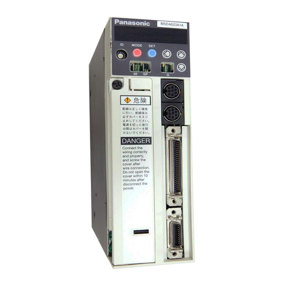
AC Servo Motor Driver
MINAS A-series
Operating Manual
Be sure give this instruction manual to the user.
• Thank you very much for your buying Panasonic AC Servo Motor Driver,A-series.
• Before use, read through this manual to ensure proper use. Keep this manual at an easily
accessible place so as to be referred anytime as necessary.
Advertisement
Table of Contents

Related Manuals for Panasonic minas a series


Summary of Contents for Panasonic minas a series
- Page 1 Operating Manual Be sure give this instruction manual to the user. • Thank you very much for your buying Panasonic AC Servo Motor Driver,A-series. • Before use, read through this manual to ensure proper use. Keep this manual at an easily...
-
Page 2: Table Of Contents
Table of Contents Before Use Safety Precautions •••••••••• 4 Parts Description ••••••••••• 12 Introduction •••••••••••••••• 8 Driver •••••••••••••••••••••••••••••••••••••••• 12 Motor ••••••••••••••••••••••••••••••••••••••••• 13 • After Opening the Package •••••••••••••• 8 Installation ••••••••••••••••• 14 • Check the Model of Driver ••••••••••••••• 8 •... -
Page 3: Conformance To Ec Directives And Ul Standards ••••••••••• App
Important Information Troubleshooting Protective Functions ••••••••••• 64 •••••••••••••••••••••••••••••• 73 Maintenance and Inspections •••••••••••••••• 71 After-Sale Service •••••••••••••••••••••• Back cover Appendixes Overview of a Communication Control Conformance to EC Directives and UL Standards ••••••••••• App. 2 Software PANATERM ••••••••••• App. 67 List of Connectable Motors ••••••••••••... - Page 4 Parts Description ••••••••••• 12 Installation ••••••••••••••••• 14 Driver •••••••••••••••••••••••••••••••••••••••• 12 Driver •••••••••••••••••••••••••••••••••••••••• 14 Motor ••••••••••••••••••••••••••••••••••••••••• 13 Motor ••••••••••••••••••••••••••••••••••••••••• 16 Parameter Setting ••••••••••• 42 Adjustments ••••••••••••••• 55 Overview •••••••••••••••••••••••••••••••••••• 42 Purposes of Gain Adjustments •••••••••••••••••• 55 meter Groups and Listing •••••••••••••••••• 42 Kinds of Gain Adjustments ••••••••••••••...
-
Page 5: Safety Precautions
Safety Precautions (Important) Observe the following precautions in order to avoid injuries of operators and other persons, and mechanical damages. The following DANGER and CAUTION symbols are used according to the level of dangers possibly occur- ring if you fail to observe the instructions or precautions indicated. Indicates a potentially hazardous situation which, if not avoided, DANGER will result in death or serious injury. - Page 6 DANGER Don't touch the rotating part of the Don't subject the product to wa- motor in motion. ter splash, corrosive gases, flam- mable gases and combustible things. Failure to observe this in- struction could result in Rotating part fire. Failure to observe this instruction could result in injuries.
- Page 7 Safety Precautions (Important) Caution Use the motor and driver in Execute the trialoperations with the the specified combination. motor fixed but without motor load connected. Connecting a load to the motor is possible only after successful trial operation. Failure to observe this in- Failure to observe this in- struction could result in fire.
- Page 8 Caution Don't hold the cables or After recovery from the power motor shaft when transpoting failure, the equipment may the motor. restart suddenly. Don't approach to the equipment during power failure. Failure to observe this instruction could result in injuries. *Provide appropriate settings as a preparedness against the accidental restart of the machine in order to ensure the safety of personnel.
-
Page 9: Introduction
Introduction After Opening the Package • After Opening the Package • Make sure that the product is what you have ordered. Check whether the product has been damaged or not during transportation. If the product is not correct, or it has been damaged, contact dealer or sales agent. Check the Model of Driver Name plate AC SERVO DRIVER... -
Page 10: Check The Model Of Motor
Check the Model of Motor Name plate Type CONT. TORQUE 0.64 Nm AC SERVO MOTOR RATING Rated output MODEL MSMA022A1A INS. CLASS B (TÜV) A (UL) Serial No INPUT 3ØAC IP65 CONNECTION Revolution rating RATED OUTPUT SER No. T98120001 RATED FREQ. RATED REV. -
Page 11: Check The Combination Of Driver And Motor
Introduction Table 1-c Motor Structure "D-cut" shafts are available Shaft Oil seal Brake for MSMA30W to 750W Straight Key way D-cut and MQMA100W to 400W. None None None None Check the Combination of Driver and Motor The driver has been designed for use in combination with the specified motors only. Check the specifications (Series symbol, output rating, voltage rating and encoder type) of the mo- tor you want to use. - Page 12 With the absolute/incremental type encoder, 17 bits Motor Amplifier Amplifier Output Revolution Encoder Series type Voltage Motor type rating rating type symbol Type1 MSDA3A1D1A MSMA3AZC** MSMA MSDA5A1D1A (Small) MSMA5AZC** MSDA011D1A MSMA011C** 100V 100W Type2 MSDA021D1A MSMA021C** 200W With the absolute/ Type2 MSDA041D1A MSMA041C**...
-
Page 13: Parts Description
Parts Description Driver ÅmTerminal block cover openedÅn ÅmTerminal block cover closedÅn Mounting bracket LED indicator button (6 digits) MODE Rotary switch (ID) Data setting MODE MODE selector switch buttons Check pins : SHIFT Cover Terminal : UP securing screw : DOWN Mains power Communication connection... -
Page 14: Motor
Motor Encoder cable Motor cable Encoder Brake cable Frame Mounting bolt holes (4) Flange Example: Small Low-Inertia Motor (MSMA Series, 750W and below) < Notes > For detailed information for each of motor types, see the drawings in the Appendix. - 13 -... -
Page 15: Installation
Installation The driver and motor should be properly installed to avoid failures, mechanical damages and injuries. Amplifier Location A Indoors, where the driver is not subjected to rain water and direct sun beams. Note that the driver is not a waterproof structure. B A void the place where the driver is subjected to corrosive gases, flammable gases, grinding liquids, oil mists, iron powders and cutting particles. - Page 16 Mounting Direction and Space Requirements • Allow enough space to ensure enough cooling. • Install fans to provide a uniform distribution of temperature in the control box. • Observe the environmental requirements for the control box, mentioned in the previous page.
-
Page 17: Motor
Installation Motor Location A Indoors, where the driver is not subjected to rain water and direct sun beams. B Avoid the place where the driver is subjected to corrosive gases, flammable gases, grind- ing liquids, oil mists, iron powders and cutting particles. C Place in a well-ventilated, and humid- and dust-free space. - Page 18 Cable: Stress Relieving A Make sure that the cables are not subjected to moments or vertical loads due to external bending forces or self-weight at the cable outlets or connections. B In case the motor is movable, secure the cable (proper one supplied together with the motor) to a stationery part (e.g.
-
Page 19: System Configuration And Wiring
System Configuration and Wiring General Wiring Diagram Main Circuits Non-Fuse Breaker (NFB) Used to protect the power lines: overcurrent will shutoff the circuit. Noise Filter (NF) Prevents the external noise from the power line, and reduces the effect of the noises gen- erated by the servo motor. - Page 20 Personal computer Communication control software PENATERM • CN SER/CN NET (to connect a PC or controller) • CN I/F (to connect a controller) • CN SIG (to connect an encoder) Encoder cable Motor cable Brake power supply(24VDC) - 19 -...
- Page 21 System Configuration and Wiring List of Available Components Amplifier Non-fuse Termi n al s Main circuit wire Required Power Noise Magnetic contactor Control powerwi r e di- breaker (L1, L2, L3, on the di a met e r Series Voltage Output (at the rated load) filter...
- Page 22 Amplifier Non-fuse Termi n al s Main circuit wire Required Power ontrol N o i s e Magnetic contactor powerwi r e diam- breaker (L1, L2, L3, on the di a met e r Series Voltage Output (at the rated load) f i l t e r ( c o n t a c t s ) eter (r and t)
-
Page 23: System Configuration And Wiring
System Configuration and Wiring Main Circuits Don't turn on the main power until the wiring is completed, to avoid electric shocks. Wiring Instructions A Detach the terminal block by removing the cover securing screw. B Make necessary connections. Use clamp terminal connectors with an insulation cover. For wire diameter and connector sizes, see List of Available Components (page 20). - Page 24 Wiring Diagrams For 3-phase 200VAC For 1-phase 100V 3 Phase AC Single Phase 100V 200V Noise Noise Filter Filter DC/DC DC/DC 172167-1 172159-1 172167-1 172159-1 (Japan AMP mode) (Japan AMP mode) (Japan AMP mode) (Japan AMP mode) White or Yellow White or Yellow Black Black...
-
Page 25: Cn Sig Connector
System configutration and wiring CN SIG Connector (For Encoder) Wiring Instructions The cable length between the driver and motor should be max. 20 m. If you use a longer cable, contact the dealer or sales agent. Power MODE Separate these wiring min. 30 cm from the main circuit wires. - Page 26 Wiring Diagrams (with a 2500P/r incremental type encoder ([A]*1) • MSMA 750W or smaller, and MQMA 172171-1 172163-1 (Japan AMP mode) (Japan AMP mode) CN SiG Yellow Orange Yellow Green Blue Pink Purple Light Biue Encorder power supply White Black Motor side Connecting cable Driver side...
- Page 27 System configutration and wiring Driver with a 17 bits absolute encoder ([C]*1) Wiring Diagram Driver with a 17 bits absolute/incremental encoder ([D]*1) • MSMA 750W or smaller, and MQMA 172169-1 172161-1 (Japan AMP mode) CN SiG (Japan AMP mode) BATT+ 3.6V+ Pink BATT-...
-
Page 28: Cn Ser And
CN SER and CN NET Connectors (For PC or Controller) • These connectors can be used as either RS232C or RS485. There are three ways for using these connectors as shown below. For RS232C communication only Connect the personal computer and the driver 1:1 through RS-232C,The PANATERM using for communication control softwere. -
Page 29: Cn I/F Connector
List of Available Components CN I/F Connector (For Controller) Wiring Instructions max. 3 m Displace the peripheral devices such as the controller max. 3 m away from the driver. MODE Controller min. 30 cm Separate these wiring min. 30 cm from the Power main circuit wires. -
Page 30: Circuits Available For Typical Control Modes
Circuits Available for Typical Control Modes - 29 -... - Page 31 System configutration and wiring - 30 -...
- Page 32 - 31 -...
- Page 33 System configutration and wiring CN I/F Connector Input Signals (Common) and their Functions Signal Symbol Function circuit COM + • Connect to (+) of an external power Control signal power (+) supply(12VDC to 24VDC). COM - • Connect to (-) of an external power supply(12VDC to 24VDC). Control signal power (-) •...
- Page 34 Signal Symbol Function circuit Counter The function differs depending on the control mode. clear page 38 Position • Clears the position error counter. Connect to COM- control to clear the counter. • Use Pr4D to select the clear mode (0 = Level, 1 = Edge) Velocity •...
- Page 35 System configutration and wiring Signal Symbol Function circuit Gain GAIN • The function depends on the value of Pr30. switching page 38 Connection Pr30 value Function to COM- Open Velocity loop: PI operation Close Velocity loop: P operation Open • 1st gain selected (Pr10, 11, 12, 13 and 14) Close •...
- Page 36 Input Signals (Velocity and Torque Control) and their Functions Signal Symbol Function circuit Velocity SPR/ < At velocity control > (torque) TRQR • This becomes velocity command input (analogue) page 39 command • You can set-up the relationship between the command (15) (GND) voltage level and the motor speed, with Pr50 (Velocity...
- Page 37 System configutration and wiring Output Signals (Common) and their Functions Signal Symbol Function circuit Servo alarm ALM + • This output(transistor) turns OFF, when the driver ALM - detects and error(trip). page 40 Servo-ready S-RDY + • This output(transistor) turns ON, when the main power is on(for S-RDY - both the driver and the motor) and no alarm is active.
- Page 38 Signal Symbol Function circuit A-phase output OA + • Provides differential outputs of the encoder signals OA - (A, B and Z phases) that come from the divider page 40 B-phase output OB + (equivalent to RS422 signals). OB - •...
-
Page 39: (Interface Circuit)
System configutration and wiring CN I/F Connector Interface Circuit (Input Circuit) SI Connecting to 12~24V 7 COM+ 4.7K se quence input signals Servo-ON or • Connect to a contact of switch and relay, or a tran- other input Relay sistor of an open collector output. •... - Page 40 AI Analogue Commend Input • There are three analogue command inputs of SPR/RTQR (14 pins), CCWTL (16 pins) and CWTL (18 pins). • The maximum permissible input voltage is ±0V. For the input impedance of these inputs, see SPR/TRQR ∂ µ12V µ...
- Page 41 System Confguration and Wiring Interface Circuit (Output Circuit) Sequence output circuit Install as per the fig. Shows with- out fail • This comprises a Darlington amplifier with an open collector. This is connected to a relay or photo coupler. ALM+ or other signal •...
- Page 42 Open Collector Output Maximum rating: • Outputs Z-phase signals among those 30V, 50mA from the encoder. The outputs are non- insulated. • Receive these signal with high-speed photo coupler at controller side, since these Z-phase signal width is normally High-speed narrow.
-
Page 43: Parameter Setting
Parameter Setting Overview This driver has various parameters that are used for adjusting or setting the features or functions of the driver. This section describes the purpose and functions of these parameters. Understanding these pa- rameters is essential for obtaining the best, application-specific operation of the driver. You can view, set and adjust these parameters using either: 1) the front touch panel or 2) your personal computer with the communication software PANATERM . - Page 44 Parameters for Selecting Function P : Position, S : Velocity, T : Torque Parameter Related control Parameter description Range Default Default mode * 0 0 0 ~ 15 — P · S · T Axis address * 0 1 0 ~ 2 —...
- Page 45 Parameter Setting Parameters for Defining the Real Time Auto Gain Tuning Parameter No. Related control Parameter description Range Default Unit mode Åñ2 0 ~ 10000 <<100>> P · S · T Inertia ratio Åñ2 0 ~ 3 P · S · T Real time auto tuning set-Up Åñ2 0 ~ 9...
- Page 46 Parameters for Position Control P : Position, S : Velocity, T : Torque Parameter No. Related control Parameter description Range Default Unit mode 1 ~ 4 Command pulse multiplier set-up 0 ~ 3 Command pulse logic inversion 0 ~ 3 Command pulse input mode set-up Å4 0 ~ 1...
- Page 47 Parameter Setting Parameters for Sequence P : Position, S : Velocity, T : Torque Parameter No. Related control Parameter description Range Default Unit mode Åñ6 0 ~ 32767 <10> Pulse In-position range Åñ6 0 ~ 10000 r/min P • S • T Zero speed Åñ6 0 ~ 10000...
-
Page 48: Setting The Parameters
Setting the Parameters • You can set the Parameters with; 1) the front touch panel or 2) Ayour personal computer with the A-series communication software PANATERM. <Note> For the use of PANATERM for parameter handling, see the instruction manual of the soft- ware. -
Page 49: Modes Structure
Parameter Setting MODE's Structure You can select a desired MODE by using the front panel button. Power ON Monitor Mode SET button MODE selector For details, see page 57 of the button Appendix part of this manual. Parameter Setting Mode SET button MODE selector See the next page. - Page 50 Using the front touch panel Turn the driver (power) ON. Press SET button. MODE Keep pressing MODE button. Select your desired MODE Parameter No. by using UP and DOWN button. Press SET button. Change the value using LEFT ARROW, UP and DOWN buttons. Press SET button.
- Page 51 Trial Run Inspections before Trial Run 1) Inspecting the wiring • Make sure that all wire connections (especially main power and motor output ) are correct. • Make sure that there are no improper grounding connections, and earth wires are properly connected. 2) Inspecting the power specifications •...
-
Page 52: Motor Load (Jog)
Trial Run without Motor Load (JOG) Use the JOG function (run with the motor and driver alone) for trial run. If the motor runs with this JOG, it means the motor and the driver are in good condition and so is the connection between them. -
Page 53: Cn I/F Connected
Trial Run Operation With CN I/F Connected Connect CN I/F. 2) Connect the control signal (COM+/-) to the power supply (12 to 24 VDC) . 3) Turn the main power (driver) ON. 4) Check the defaults of the parameters. 5) Connect between SRV-ON (CN I/F pin 29) and COM- (CN I/F pin 41) to make Servo-On active. The motor will be kept excited. - Page 54 Set-up of motor speed and input pulse frequency Input pulse Motor Pr 4A Pr 46 frequency speed Pr 4B (PPS) (r/min) 17 bits 2500P/r 500K 3000 10000 10000 10000 250K 3000 10000 5000 5000 100K 3000 10000 2000 2000 500K 1500 5000 10000...
- Page 55 Trial Run Run at Velocity Control Mode 1) Apply a DC voltage between the velocity command input SPR (CN I/F pin 14) and GND (CN I/F pin 15). Increase the voltage gradually from 0, and make sure that the motor runs and the speed change accord- ingly.
-
Page 56: Purposes Of Gain Adjustments
Adjustments Purposes of Gain Adjustment In case of the servo motor, the motor is required to act per any command without any time delay, or without missing any commands. To ensure this, gain adjustment is necessary. <Example: ball screw> Gain set-up: low Gain set-up: high +Feed forward set-up +2000... - Page 57 Adjustments Applicability of Automatic Adjustment Item Conditions Load inertia Must be at least three times as large as the motor inertia, but not greater than 20 times. Load • The machine (motor load) and its coupling must have a higher mechanical stiffness. •...
-
Page 58: How To Adjust Gain
How to Adjust Gain <Note> • Pay extra attention to the safety. • If the machine enter to oscillation ( abnormal sound and vibration) , shut off the power immediately, or change to Servo-OFF. - 57 -... -
Page 59: Normalauto-Gain" Tuning
Adjustments How to Use "Normal Auto Gain Tuning 1) Select the Normal Auto Gain Tuning Motor speed display Mode. (initial display) Press SET button once and press MODE switching button three times. See page 48. Mechanical stiffness value 2) Press UP orDOWN button to select the stiffness of the machine. - Page 60 <Notes> Symptom Cause Remedy • Avoid operation near the limit switch or home Either one of Alarm, Servo-Off or Po- Error message position sensor. sition Error Counter Clear activated. displayed • Turn to Servo-ON. The load inertia cannot be calculated •...
-
Page 61: How To Adjust Gain Manually
Adjustment How to Adjust Gain Manually Before Adjustment You may adjust the gains by viewing or hearing the motions and sound of the machine during opera- tion. But, to adjust the gains more quickly and precisely, you can obtain quicker and secure adjust- ment by analog wave form monitoring. - Page 62 How to Adjust the Gain at Position Control Mode 1) Start the motor (machine). 2) Set Pr10 (1st Position Loop Gain) to 50. 3) Increase the value of Pr11 (1st Velocity Loop Gain) gradually until the motor (machine) does not generate abnormal sound or vibration.
- Page 63 Adjustment How to improve the response further You can manually adjust the 2nd gain. With the 2nd gain adjustment, you can expect quicker response. 1st Gain 2nd Gain Pr10 Pr18 1st Position Loop Gain 2nd Position Loop Gain Pr11 Pr19 1st Velocity Loop Gain 2nd Velocity Loop Gain Pr12...
- Page 64 To reduce the mechanical resonance If the machine is not stiff, vibration and noise may be generated due to the resonance by shaft torsion, and you mey not be able to set-up the higher gains. You can suppress the resonance by 2 types of the filters.
-
Page 65: Protective Functions
Protective Functions What are the Protective Functions? The MINAS driver has various protective functions. When one of the protections is activated, the motor trips according to the timing chart shown in "Error Handling" in Appendix, and the Servo Alarm Output (ALM) is turned off. Actions to be taken after trip events •... - Page 66 Alarm Protection Cause Countermeasures Code No. 1) The internal regenerative discharge resistor is 1) Measure the P-B1 resistance of the driver us- O v e r v o l t a g e disconnected. ing a circuit tester. If it read Åá, the connec- error tion is broken.
- Page 67 Protective Functions Alarm Protection Cause Countermeasures Code No. The current flowing in the converter is larger *Overcurrent than the specified value. error 1) The driver failed (due to defective circuits 1) Disconnect the motor wires, and enter or IGBT parts). Servo-ON.
- Page 68 Alarm Protection Cause Countermeasures Code No. Overload protection is activated via the Monitor the torque (current wave) using an Overload specified time limiting operation when the oscilloscope to check whether the torque is error integration of a torque command exceeds surging or not.
- Page 69 Protective Functions Alarm Cause Countermeasures Protection Code No. * Encoder A/B- No A- and B-phase pulse is detected. The 11- Correct the encoder wiring per the wiring dia- wire encoder failed. gram. Correct the connection of the pins. phase error Due to no communication between the encoder * Encoder communication...
- Page 70 Alarm Protection Cause Countermeasures Code No. Command The command pulse is larger than 500 kpps at Reduce the multiplication factor by adjusting the pulse sealer the entrance of the position error counter. The values of Pr46 through Pr4B, and then adjust error scale ratios set by Pr46 through Pr4B (numera- the scale ratios so that the command pulse fre-...
- Page 71 Protective Functions Alarm Protection Cause Countermeasures Code No. The power of the encoder is out. Check the voltage of the battery. Connect to Absolute the battery, and then clear the encoder using system the absolute encoder clear mode contained down error in the auxiliary function (see Details of Op- eration in Appendix).
-
Page 72: Maintenance And Inspections
Maintenance and Inspections • Routine maintenance and inspections are essential for proper and satisfactory operation of the driver and motor. Notes to Maintenance/Inspections Personnel 1)Power-on/off operations should be done by the operators themselves. 2)For a while after power off, the internal circuits is kept charged at higher voltage. Inspections should be done a while (about 10 minutes), after the power is turned off and the LED lamp on the panel is extinguished. - Page 73 Maintenance and Inspections Replacement Guidance Parts replacement cycles depend on the actual operating conditions and how the equipment has been used. Defective parts should be replaced or repaired immediately. Dismantling for inspections or repairs should be done by our company (or our sales agents).
- Page 74 Troubleshooting The motor does not rotate. [Check Points] Alarm Code No. displayed? Parameter values correct? The voltage of the power is correct? Is the power fed? Power line connections Controller firmly secured? Abnormal sound from the motor? CN I/F connections correct? The magnetic brake Not loosened?
- Page 75 Troubleshooting The motor does not rotate. Category Causes Countermeasures Parameters The control mode selected is not cor- Check the value of Pr02 (control mode set-up). rect. 0: position control, 1: velocity control, 2: torque control The internal velocity command Check the value of Pr05 (Internal speed swiching). (switching between internal and exter- 0: At analogue velocity command set-up, nal commands) does not work.
- Page 76 The rotation is not smooth. The motor rotates slowly even if the target speed is zero in the speed control mode. Category Causes Countermeasures Parameters The control mode selection is not cor- With the position control mode selected, if Pr02 is set to other rect.
- Page 77 Troubleshooting Category Causes Countermeasures Velocity commands contain noises. Use shielded cables for connection to CN I/F. Power and sig- Wiring nal cables should be separated by at least 30 cm and put in duct. Improper offset Measure the voltage between CN I/F pins 14 and 15 (veloc- ity command inputs) using a circuit tester and/or oscilloscope.
- Page 78 Category Causes Countermeasures Wiring CN I/F signals are chattering: 1) Check the wiring and connections between CN I/F pins 29 1) Servo-ON signals and 41 by monitoring the display of input and output signals status. Modify the wiring so that Servo-ON signals can be made active correctly.
- Page 79 Troubleshooting Category Causes Countermeasures Wiring Z-phase signal is not output. Monitor the Z-phase signal using an oscilloscope. Check that CN I/F Pin 13 is connected to the ground terminal of the con- troller. Connect the open collector to the ground of the driver. Replace the driver and controller, or repair them.
- Page 80 Overshoot or undershoot The motor overheats (burnt) Category Causes Countermeasures Adjustment Gains are not correct. Check the gains using the wave form graphics monitoring function of PANATERM, speed monitor (SP) and/or torque monitor (IM). Adjust the gains. See "Adjustments" chapter. Installation Load inertia is too large.
- Page 81 Troubleshooting The motor speed does not increase up to the specified value. The speed (movement) is too large or small. Countermeasures Category Causes Check that the value of Pr50 (velocity command input gain) Parameter The velocity command input gain is is 500 (i.e.
-
Page 82: Appendixes
Appendixes Conform to EC Directives and UL Standards App. 2 ○ ○ ○ ○ ○ ○ List of Connectable Motors App. 7 ○ ○ ○ ○ ○ ○ ○ ○ ○ ○ ○ ○ ○ ○ ○ ○ ○ How to Use •... - Page 83 Conformance to EC Directives and UL Standards EC Directives The EC Directives apply to all such electronic products as those having specific functions and directly sold to general consumers in EU countries. These products are required to meet the EU unified standards and to be furnished with CE Marking. Our product, AC servo, has specific functions, but is not sold directly to general consumers, i.e.
- Page 84 Peripheral Equipment Environment The servo driver should be used under Contamination Level 2 or 1 specified by IEC60664-1 (housing the driver in an IP54 control box). Control box Controller Insulated power for interface CN–I/F AC servo driver Noise filter for Noise filter for signal lines signal lines...
- Page 85 Noise Filters for Signal Lines Install noise filters. Install noise filters (specially designed for signal wires) for all cables (power, motor, encoder and interface wires). Grounding 1) Connect between the servo driver's protective earth terminal and control box's protec- tive earth (PE) to prevent electric shocks. 2) Multiple connections to a single protective earth terminal should be avoided.
- Page 86 Surge Absorber Optional Part No. Manufacturer's Product No. M a n u f a c t u r e r D V O P 1 4 5 0 R•A•V-781BXZ-4 Okaya Electric Industries Co., Ltd. ø4.2 x 0.2 UL-1015 AWG16 Circuit diagram 41 x 1 Install noise filfers Optional Part No.
- Page 87 Noise Filters for Signal Lines Noise Filter Optional Part No. Manufacturer's Product No. Manufacturer D V O P 1 4 4 1 3 S U P - A 1 0 H - E R - 4 Okaya Electric D V O P 1 4 4 2 3 S U P - A 3 0 H - E R - 4 Industries Co., Ltd.
- Page 88 List of Motors applicable to Drivers Driver with a 2500 P/r incremental encoder Applicable motors D r i v e r s Size O u t p u t Velocity Product name E n c o d e r Series Voltage r a t i n g r a t i n g...
- Page 89 List of Motors applicable to Drivers Driver with a 17 bits absolute/incremental encoder Applicable motors Size Velocity Drivers Output Encoder Voltage Product name rating rating MDMA MDDA083DIA MDMA082D** 750W Size MDDA103DIA MDMA102D** 1.0kW 4 - 2 MDDA153DIA MDMA152D** 1.5kW MDDA203DIA MDMA202D** 2.0kW Size...
- Page 90 Holding brake The brake is to hold the work (movable part coupled to a vertical motor axis) to prevent it from falling by gravity in case the servo power is lost. <Caution> The holding brake is to hold the work, not stop its m o t i o n .
- Page 91 Holding brake BRK-OFF Signal • See Timing Chart describing the timing of issuing BRK-OFF signal, e.g. to release the brake after power-on, and activate the brake in case a servo-off/alarm occurs during the operation of the motor. • The timing (delay) of deactivating BRK-OFF signal (i.e. activating the brake) after the motor is freed into a non-excited status in case of Servo-OFF or alarm event can be adjusted by using Pr6B (brake output delay time set-up at motor in motion).
- Page 92 Holding Brake Specifications Allowable Allowable Excitation Capacity Static friction Inertia Absorption Releasing Releasing M o t o r thermal overall current torque x 10 Å|4 time t i m e voltage equivalent thermal (DC current (A)) of work per equivalent of (N•m) (kg•m (ms)
- Page 93 Dynamic Brake (DB) The driver has a dynamic brake for emergency use. Observe the following precautions. <Notes> 1. The dynamic brake should be used for emergency stop only. Do not start or stop the motor by switching servo-on signal on or off. Otherwise the dynamic brake circuit may be broken.
- Page 94 Options of the operation through deceleration and stop by turning on Servo-OFF (Pr69) Operating conditions Sequence Position at Servo-OFF (Pr69) During deceleration After stop error counter Pr69 Clear Free run Free run Free run Free run Hold Free run Free run Free run Free run Options of the operation through deceleration and stop by turning on a protective function (Pr68)
- Page 95 Timing Chart After Power ON (receiving Servo-ON signal) Control power Control voltage 5V Main power Dynamic brake Activated Released approx. 50 ms Free (not energized) Motor energized Energized Brake release Activated (braking) Released (BRK-OFF) approx. 2 ms Reset Internal reset Released approx.
- Page 96 After an Alarm event (during Servo-ON) Alarm Error (alarmed) Normal Dynamic brake Operation (braking) *2 Free (not energized) approx.1 to 5 ms Motor energized Energized Servo ready Not ready Ready (S-RDY) Servo alarm Alarm Not alarm (ALM) Set by Pr6B Brake release Braking Released...
- Page 97 Timing Chart After an Alarm is cleared (during Servo-ON) 120 ms or more Alarm clear Entry of Clear signal (A-CLR) Dynamic brake Operation (braking) Released Free (not energized) approx, 50 ms Motor energized Energized Brake release Braking Released (BRK-OFF) Servo ready Not ready Ready (S-RDY)
- Page 98 Servo-ON/OFF operation when the motor is in operation With Servo-ON entered Servo-ON Servo-OFF Servo-ON (SRV-ON) Dynamic brake Braking Released Free (not energized) Motor Energized approx. 50 ms Brake release Braking Released (BRK-OFF) Servo-ON does not become active until the motor speed decreases to about 30 r/min or less. approx.
- Page 99 Acceptable Loads on Output Axes Acceptable Loads on Output Axes Radial load (P) Thrust load (A and B) Unit: N (1 kgf = 9.8 N) D e s i g n Acceptable during operation M o t o r Motor capacity series Radial load Thrust load...
- Page 100 Initialization (Precautions) In the operation of initialization (returning to the home position), if the initialization signal (Z-phase signal from the encoder) is entered before the motor is not substantially decelerated (after the proximity sensor is activated), the motor may not stop at the required position.
-
Page 101: Absolute" Driver
"Absolute" Driver In case of using an absolute encoder, or in case of using an absolute/incremental encoder as an absolute encoder, connect a battery for operating the absolute encoder, and set Pr0B (absolute encoder set-up) to 0. With this setting, the controller can know the current position of the motor, and the absolute system without any operation of initialization will become available. - Page 102 Encoder status (1 means the occurrence of an error) Encoder status (L) Bit 7 Bit 6 Bit 5 Bit 4 Bit 3 Bit 2 Bit 1 Bit 0 Over-speed Err42 (absolute over-speed error) Full absolute status Err47 (absolute status error) Count error Err44 (absolute single-turn counter error)
- Page 103 "Absolute" Driver RS232C Communication Protocol RS232C Switch, etc. Host Host RSW(ID)=0 RSW(ID)=1 RSW(ID)=2 RSW(ID)=3 RS485 RS485 RS485 MODE MODE MODE MODE MODE MODE MODE MODE Max. 16 axes Controller Driver CN SER SN751701 or equivalent RS232C interface CN I/F Positioning controller CN SIG Motor...
- Page 104 RS232C Communication Protocol For the transfer of commands, see the instructions of the controller. RS232C communication is possible with Servo Ready output ON. Start of transfer 05h sent *1 and *2 data depend on the value of RSW(ID) on the LED touch panel. 04h received RSW (ID) *1 data...
- Page 105 "Absolute" Driver R S 4 8 5 C o n n e c t i o n RS485 Module ID = 0 MODE MODE MODE MODE Host • • • RSW(ID)=1 RSW(ID)=2 RSW(ID)=3 RSW(ID)=4 Max. 15 axes Controller Driver CN NET RS485 interface ADM485 or equivalent RS485+...
- Page 106 RS485 Communication Protocol For the transfer of commands, see the instructions of the controller. RS485 communication is possible with Servo Ready output ON. The following flow chart shows the communication when RSW(ID) = 1. Start of transfer *1, *2 and *3 data depend on the value of 81h sent 05h sent RSW(ID) on the LED touch panel.
- Page 107 "Absolute" Driver How to install the battery 1. Cut away the upper right corner of the terminal block cover for types 1 through 3 1Remove the screw. 2Remove the cover, and cut away its upper right corner. Driver Use nippers. 2.
- Page 108 1 . Remove the battery cover for Types 4-2, 4-3 and 5 1Press mark and remove the cover. Driver Battery cover Snap the battery 2. Set the battery into the holder. Å@Å@cover into place Connector Insert the coverwhile pressing mark. Connect the 1Press the lug cable.
-
Page 109: Full Close" Driver
"Full Close" Driver Combining a certain type of the driver with an external scale (linear type), you can use the full-close driver for precise positioning. Drivers available for "full-close" use are the 17-bit absolute driver and 17-bit absolute/incremental driver. details, see Full-Close Specifications. Wiring of main circuit For wiring, see page 22. - Page 110 CN I/F Connector See Full-Close Specifications. For wiring, see page 28. Parameter Listing See Full-Close Specifications. Connection to an external scale max. 500 kpps CN SIG External scale Ω Ω DS26C32ATM or equivalent Ω Ω Ω Twist-paired wires • Relationship between signal from external scale and rotating direction CCW Rotation CW Rotation EXB precedes EXA by 90 degrees, and...
-
Page 111: Details Of Parameters
Details of Parameters Parameters for Function Selection Default setting is shown by [ PrNo. P a r a m e t e r Value F u n c t i o n Axis address If multiple axes are used, it is necessary for the river to identify the current axis that is accessed by the host (e.g. - Page 112 PrNo. P a r a m e t e r Value F u n c t i o n Control mode You can set the control mode to be used. s e t - u p Control mode Value 1 s t m o d e 2nd mode *2 P o s i t i o n V e l o c i t y...
- Page 113 Details of Parameters PrNo. P a r a m e t e r Value F u n c t i o n O v e r t r a v e l 0 ~ 1 For linear motion or other similar motion, overtraveling of the work may cause mechanical input inhibit damages.
- Page 114 PrNo. P a r a m e t e r Value F u n c t i o n Internal speed 0 ~ 2 • You can easily set-up the internal speed with contact s w i t c h i n g inputs only.
- Page 115 Details of Parameters PrNo. P a r a m e t e r Value F u n c t i o n Internal speed switching (continued) • Example: 4-speed operation using the internal velocity commands To run/stop the motor, you need zero speed clamp input(ZEROSPD) and Servo-ON input(SRV-ON) in addition to CL/INH input.
- Page 116 PrNo. P a r a m e t e r Value F u n c t i o n Speed 0 ~ 9 You can select/set-up the relationship between the voltage to be m o n i t o r ( S P ) fed-out to the speed monitor signal output (SPM: CN I/F Pin 43) selection and the actual speed (or command velocity) of the motor.
- Page 117 Details of Parameters PrNo. P a r a m e t e r Value F u n c t i o n ZSP output 0 ~ 5 You can define the functions of the zero speed s e l e c t i o n detection output (ZSP: CN I/F pin 12).
- Page 118 Parameters for Time Constants of Gains and Filters: Related to Real Time Auto Tuning PrNo. P a r a m e t e r Value U n i t F u n c t i o n 1st position 10 ~ •...
- Page 119 Details of Parameters PrNo. P a r a m e t e r Value U n i t F u n c t i o n 2nd position 10 ~ • This driver provides 2(two) sets (1st. and 2nd.) of loop gain 2000 gain and time constant for position loop, velocity...
- Page 120 Parameters for real time gain tuning PrNo. P a r a m e t e r Value U n i t F u n c t i o n Inertia ratio • You can set-up the ratio of load inertia to the 10000 motor's rotor inertia.
- Page 121 Details of Parameters Parameters for Switching to 2nd Gains PrNo. P a r a m e t e r R a n g e U n i t F u n c t i o n d e s c r i p t i o n 0 ~ 1 ––...
- Page 122 P a r a m e t e r R a n g e PrNo. U n i t F u n c t i o n d e s c r i p t i o n x 166 µs Position control •...
- Page 123 Details of Parameters PrNo. P a r a m e t e r R a n g e U n i t F u n c t i o n d e s c r i p t i o n 0 ~ 5 –––...
- Page 124 Parameters for Position Control P a r a m e t e r R a n g e PrNo. F u n c t i o n d e s c r i p t i o n 1 ~ 4 Command pulse You can set-up the multiplication when [quadrature pulse input] multiplier set-up...
- Page 125 Details of Parameters PrNo. P a r a m e t e r R a n g e F u n c t i o n d e s c r i p t i o n Maximum permissible frequency and minimum required time width of command pulse inputs (continued) I/F for inputting Maximum...
- Page 126 P a r a m e t e r R a n g e PrNo. F u n c t i o n d e s c r i p t i o n 0 ~ 1 Pulse output When the motor runs CW, the B-phase pulse advances the A-phase pulse logic inversion (when the motor runs CCW, the B-phase pulse delays from the A-phase pulse).
- Page 127 Details of Parameters PrNo. P a r a m e t e r R a n g e F u n c t i o n d e s c r i p t i o n You can select the numerator of the command scalar. *1 Select the 1st.
- Page 128 P a r a m e t e r R a n g e PrNo. F u n c t i o n d e s c r i p t i o n 0 ~ 7 S m o o t h i n g This filter is a primary delay filter that is inserted after the scaling function in filter set-up the command pulse input portion.
- Page 129 Details of Parameters Parameters for Velocity Control PrNo. P a r a m e t e r R a n g e F u n c t i o n d e s c r i p t i o n 10 ~ V e l o c i t y You can set-up the relationship between the motor speed and the voltage...
- Page 130 P a r a m e t e r R a n g e PrNo. F u n c t i o n d e s c r i p t i o n - 2047 • You can adjust the offset of the external analogue velocity command sys- V e l o c i t y tem including that the controller.
- Page 131 Details of Parameters PrNo. P a r a m e t e r R a n g e F u n c t i o n d e s c r i p t i o n A c c e l e r a t i o n Y o u c a n c o n t r o l t h e s p e e d w h i l e a p p l y i n g t h e a c c e l e r a t i o n / deceleration to the velocity commands in the driver, at velocity time set-up...
- Page 132 Parameters for Torque Control P a r a m e t e r R a n g e PrNo. F u n c t i o n d e s c r i p t i o n • The unit of the set-up is [0.1V/100%]. Enter the required volt- Torque (continued) 300[%]...
- Page 133 Details of Parameters Parameters for various sequences PrNo. P a r a m e t e r R a n g e F u n c t i o n d e s c r i p t i o n In-position •...
- Page 134 P a r a m e t e r R a n g e PrNo. F u n c t i o n d e s c r i p t i o n A t - s p e e d •...
- Page 135 Details of Parameters PrNo. P a r a m e t e r R a n g e F u n c t i o n d e s c r i p t i o n 0 ~ 1 UVtrip selection at You can select whether or not to activate the under-voltage trip in case the main power-off...
- Page 136 P a r a m e t e r R a n g e PrNo. F u n c t i o n d e s c r i p t i o n Sequence Defines the conditions for decelerating the motor and keeping 0 ~ 3 the motor stopped after one of the driver's protective functions at alarm...
- Page 137 Details of Parameters PrNo. P a r a m e t e r R a n g e F u n c t i o n d e s c r i p t i o n Mechanical Defines the duration from OFF of the brake release signal (BRK- brake action OFF) (i.e.
-
Page 138: Details Of Operation
Details of Operation (Monitor Mode) Motor Mode Operation Motor speed 1) Turn on the mains power (driver). (initial display) 2) Open the Monitor mode Select thisdisplay. (see Parameter Setting and MODE's Structure). 3) Select a mode that you want to view. Mode selection M o n i t o r i n g / E x e c u t i o n Meaning... - Page 139 Details of Operation (Monitor Mode) Details of Monitor Mode Indication of position error, motor speed and torque D a t a •••••• Position error Display the reading (pulse count) of the position error counter with an indication of polarity (unit: P). (+): Error in CCW direction (-): Error in CW direction ••••••...
- Page 140 Display of I/O signals status Display the status of control (input) and output signals via the CN I/F connectors. Use this information for checking the wiring connections. Active Inactive Signal No. (hexadecimal digit 0 to 1F) Input signa Output signal •...
- Page 141 Details of Operation (Monitor Mode) Signal Numbers and Names Input signals Output signals Signal description S y m b o l Pin No. Signal description S y m b o l Pin No. SRV-ON S-RDY 35 (34) Servo-ON Servo-ready A-CLR A L M 37 (36) Alarm clear...
- Page 142 Viewing the causes and history of an alarm • You can view the latest 14 alarms including the current one. Alarm Code No. (if no errors are occurring, -- is displayed) : Current alarm : No.0 alarm (the latest (current) alarm) : No.1 alarm •...
- Page 143 Details of Operation (Monitor Mode) Alarm Display A : FAlarm occurred – : FNo alarms occurred Over-regeneration alarm: over 85% of the acceptable consumption of the regenerative discharge resistor Overload alarm: over 85% of the acceptable load level Battery alarm: under the acceptable voltage level <Notes>...
- Page 144 Operation in the Parameter Setting Mode Operation in the Mode Selection mode Parameter No. (hexadecimal digit) <Notes> Display of "r" in this field means that the parameter has been modified, so it must be downloaded to EEPROM. After downloading, the parameter value is not valid until the power is turned off and turned on again.
- Page 145 Details of Parameters (Auxiliary Function Mode) Auxiliary Function Mode Operation Mode selection Execution A u t o m a t i c o f f s e t a d j u s t m e n t mode Motor trial mode Alarm clear mode Absolute encoder clear mode Press...
- Page 146 <Notes> 1. The automatic offset adjustment mode is not effective for the position control mode. 2. If the input voltage is over the adjustment range ( ±25% of the maximum input voltage), the mode cannot work (an error occurs). Make sure that the input voltage is 0V. 3.
- Page 147 Details of Parameters (Auxiliary Function Mode) Absolute Encoder Clear Mode This mode is to clear the multi-turn data of the absolute encoder, and clear the alarms regarding the encoder. Procedure 1) Select the absolute encoder clear mode (refer to page 39 in Appendix). will appear.
-
Page 148: Overview Of A Communication Control
Overview of a Communication Control Software PANATERM How to Connect D V O P 1 1 6 0 (For PC-98 series) D V O P 1 9 6 0 ( D O S / V ) MODE <Note> RS232C cable * Do not connect to CN NET. - Page 149 Overview of a Communication Control Software PANATERM Starting PANATERM <Notes> 1. Once you install PANATERM on your hard disc, you do not have to install it again for next use. 2. Before using PANATERM, the driver, power supply, motor and encoder should be connected. For the proce- dure for starting PANATERM, see the Windows manual Procedure Turn on your personal computer.
-
Page 150: Optional Parts
Optional Parts MINAS-A series Cables Dwg. No. Motor type Cable Part No. R e m a r k s 1 - 1 MSMA30 ~ 750W MFECAO**OLAA Encoder cable (17 bits, 7 wires) MQMA100 ~ 400W for absolute/incremental encoders 2 - 1 MFECAO**OEAA Encoder cable (2500 pulses, 11 wires), incremental encoders... - Page 151 Optional Parts Encoder Cables MFECA0**0LAA fig1-1 L (m) Part No. M F E C A 0 0 3 0 L A A M F E C A 0 0 5 0 L A A M F E C A 0 1 0 0 L A A M F E C A 0 2 0 0 L A A (14) MFECA0**0LSA...
- Page 152 Motor Cables (RobotopR, 600V DP) Robotop is the trademark of Sumitomo Denso. MFMCA0**0EET fig 3-1 (50) (50) L (m) Part No. M F M C A 0 0 3 0 E E T M F M C A 0 0 5 0 E E T M F M C A 0 1 0 0 E E T M F M C A 0 2 0 0 E E T (10.0)
- Page 153 Optional Parts Motor (with Brake) Cables (Robotop , 600V DP) ® MFMCB0**0GET fig 4-1 (Brake cable) (40) (50) L (m) Part No. M F M C B 0 0 3 0 G E T M F M C B 0 0 5 0 G E T M F M C B 0 1 0 0 G E T M F M C B 0 2 0 0 G E T (5.6)
- Page 154 Connector Kits for External Equipment Part No. DV0P0980 Components I t e m Manufacturer's Part No. Q u a n t i t y Manufacturer R e m a r k s 1 0 1 5 0 - 3 0 0 0 V E P l u g SUMITOMO For CN I/F...
- Page 155 Optional Parts Connector Kits for Motor and Encoder • Used for: MSMA 30W to 750W with a17-bit absolute encoder MQMA 100w to 400W 1) Part No. DVOP2110 2) Components Item Manufacturer's Part No. Q u a n t i t y Manufacturer Remarks 1 0 1 2 0 - 3 0 0 0 V E...
- Page 156 • Used for : MSMA 1.0kW to 2.5kW with a 17-bit absolute/incremental MDMA 0.75kW to 2.5kW encoder or 2500-pulse incremental MHMA 0.5kW to 1.5kW e n c o d e r MGMA 300W to 900kW w i t h o u t b r a k e DVOP0960 1) Part No.
- Page 157 Optional Parts • Used for : MSMA 1.0kW to 2.5kW with a 17-bit absolute/incremental MDMA 0.75kW to 2.5kW encoder or 2500-pulse incremental MHMA 0.5kW to 1.5kW e n c o d e r MGMA 300W to 900W with brake with a 17-bit absolute/incremental MFM 0.4kW to 1.5kW encoder or 2500-pulse incremental e n c o d e r...
- Page 158 <Notes> 1. Plugs, shells and other parts may be equivalents of other manufacturer's make. 2. Alignment of CN SIG pins 2500P/R 17bit RX / TX RX / TX Shield Shield BATT BATT <Notes> 1. The tables above show the pins alignment, looking from where the plugs are soldered. 2.
- Page 159 Optional Parts Interface Cables 1) Part No. DVOP2190 2) Dimension 2000 +200 12.7 3) Wire table Pin No. Wire color Pin No. Wire color Pin No. Wire color Pin No. Wire color Pin No. Wire color Orange (Red 1) Orange (Brack 2) Orange (Red 3) Orange (Red 4) Orange (Red 5)
- Page 160 Communication Cables (for connection to personal computer) 1) Part No. DVOP1160 (for PC98 series) +200 2000 Mini DIN8P, MD connector, eight clamp terminals "D" subconnector 25P, eight clamp terminals 2) Part No. DVOP1960 (for DOS/V) +200 2000 Mini DIN8P, MD connector, "D"...
- Page 161 Optional Parts Brackets for Mounting the Driver Driver Screws *1 Outer dimension Part No. type Upper and lower brackets (each 1) for front panel mounting M3 x 8 pan D V O P Type 1 head screw 2 1 0 0 2-M3 Countersinking 2-M3 Countersinking x 4 pcs.
- Page 162 External Regenerative Discharge Resistor M o d e l P r o d u c t Part.No. n u m b e r Spesifications R e s i s t a n c e D V 0 P 1 9 8 0 R H 1 5 0 M 50Ω...
- Page 163 Optional Parts Battery and Battery Holder for Absolute Encoder Lead wires Battery (for driver types 1 to 5) A Part No. DVOP2060 B Lithium battery, Toshiba Battery make ER6V, 3.6V, 2000mAh Battery Holder (for driver types 1 to 3) A Part No. DVOP2061 <Notes>...
- Page 164 R e a c t r e Driver R e a c t o r Driver R e a c t o r Voltage Voltage Rated output Rated output Part No. Part No. series series M S D A 1 0 0 V 30W ~ 100W M S D A 2 0 0 V...
- Page 165 Recommended Parts Surge Absorber for Motor Brake m o t o r Surge absorber for brake MSMA30W ~ 1.0kW • C-5A2 or Z15D151 MQMA100W ~ 400W Ishizuka.co. MHMA2.0kW ~ 5.0kW MGMA600W ~ 2.0kW MSMA1.5kW ~ 5.0kW • C-5A3 or Z15D151 MDMA750W Ishizuka.co.
- Page 166 Peripheral Equipment Manufacturers 3 . 1 9 9 9 . p r e s e n t M a n u f a c t u r e r / a g e n t T e l E q u i p m e n t No-fuse breaker, magnetic Matsushita Electric Works, 0 6 - 6 9 0 8 - 1 1 3 1...
- Page 167 Dimensions MSMA Series 30W ~ 750W Encoder wire dimension LH 30W ~ 100W 230mm 200W ~ 750W 220mm Encoder specifications A 2500 P/r incremental encoder 17 bits absolute encoder Model Output(W) MSMA3AZA1 M S M A 5 Z A 1 MSMA01 A1 1 0 0 1 0 3...
- Page 168 "D" cut type 4-øLZ KWh9 Key way type Weight (kg) 3 . 4 5 . 8 6 . 5 6 . 5 0 . 2 7 1 2 . 5 6 . 2 7 . 5 7 . 5 0 . 3 4 0 .
- Page 169 Dimensions MSMA Series 1.0 ~ 5.0kW Encoder specifications 2500 P/r incremental encoder 17 bits absolute encoder Model Output(W) M S M A 1 0 2 A 1 1 . 0 1 7 2 1 0 0 1 2 0 M S M A 1 5 2 A 1 1 .
- Page 170 MSMA 1.0~2.5kW MSMA 3.0~3.5kW 4.0~5.0kW 4-øLZ KWh9 øLP øLQ Weight (kg) –– –– 6 . 6 1 5 . 5 4 . 5 5 . 1 6 . 5 7 . 5 wide 9 9 . 3 1 0 . 9 ––...
- Page 171 Dimensions MQMA Series 100W ~ 400W Encoder specifications 2500 P/r incremental encoder 17 bits absolute encoder Model Output(W) M Q M A 0 1 1 0 0 M Q M A 0 2 2 0 0 M Q M A 0 4 4 0 0 M Q M A 0 1 1 0 0...
- Page 172 "D" cut type 4-ø4.5 KWh9 Weight (kg) 1 2 . 5 6 . 2 7 . 5 7 . 5 0 . 6 5 8 . 5 1 . 3 2 2 . 5 1 2 . 5 1 2 . 5 1 .
- Page 173 Dimensions MDMA Series 750W ~ 5.0kW Encoder specifications 2500 P/r incremental encoder 17 bits absolute encoder Model Output(W) M D M A 0 8 2 A 1 0 . 7 5 1 4 4 –– 1 1 0 1 2 0 1 6 2 M D M A 1 0 2 A 1 1 .
- Page 174 MDMA 1.0~5.0kW MDMA 750W 4-øLZ KWh9 øLP øLQ Weight (kg) wide 9 1 5 . 5 4 . 8 –– –– 6 . 8 –– –– 8 . 5 –– –– 1 0 . 6 –– –– 1 2 . 8 ––...
- Page 175 Dimensions MHMA Series 500W ~ 5.0kW Encoder specifications 2500 P/r incremental encoder 17 bits absolute encoder Model Output(W) M H M A 0 5 2 A 1 0 . 5 1 4 7 1 4 5 1 1 0 1 3 0 1 6 5 M H M A 1 0 2 A 1 1 .
- Page 176 4-øLZ KWh9 Weight (kg) 5 . 3 8 . 9 1 0 . 0 3 . 2 1 3 . 5 1 6 . 0 1 8 . 2 2 2 . 0 2 6 . 7 5 . 3 8 .
- Page 177 Dimensions MFMA Series 400W ~ 4.5kW Encoder specifications 2500 P/r incremental encoder 17 bits absolute encoder Model Output(W) M F M A 0 4 2 A 1 0 . 4 1 1 7 1 4 5 1 1 0 1 3 0 1 6 5 M F M A 0 8 2 A 1 0 .
- Page 178 MFMA400W ~ 1.5kW MFMA2.5 ~ 4.5kW 4-øLZ 4-øLZ KWh9 øLA øLA Weight (kg) 1 5 . 5 4 . 7 3 . 2 1 3 . 5 8 . 6 1 1 . 0 1 4 . 8 1 5 . 5 1 9 .
- Page 179 Dimensions MGMA Series 300W ~ 4.5kW MGMA 300W~3.0kW MGMA 4.5kW eyebolt call 10 LF LE Encoder specifications 2500 P/r incremental encoder 17 bits absolute encoder Model Output(W) M G M A 0 3 2 A 1 0 . 3 1 2 2 1 4 5 1 1 0 1 3 0...
- Page 180 MGMA 300W ~ 3.0kW MGMA 4.5kW 4-øLZ 4-øLZ KWh9 Weight (kg) 5 . 1 6 . 8 8 . 5 3 . 2 1 3 . 5 1 5 . 5 1 7 . 5 2 5 . 0 1 1 3 3 4 .
- Page 181 Dimensions Driver Type 1 Approximate weight : 1.0 kg Front panel mount type Back panel mount type (front panel mounting is optional) (Standard) Mounting bracket (optional: DVOP2100) Mounting bracket (standard) MODE MODE Nameplate Nameplate Nameplate Mounting bracket Mounting bracket (standerd) (optional: DVOP2100) - App.
- Page 182 Driver Type 2 Approximate weight : 1.1 kg Front panel mount type Back panel mount type (front panel mounting is optional) (Standard) Mounting bracket (optional: DVOP2100) 32.5 32.5 Mounting bracket (standerd) MODE MODE Nameplate Nameplate Nameplate Mounting bracket Mounting bracket (standerd) (optional: DVOP2101) - App.
- Page 183 Dimensions Driver Type 3 Approximate weight : 1.4 kg Front panel mount type Back panel mount type (front panel mounting is optional) (Standard) Mounting bracket (optional: DVOP2101) 32.5 32.5 Mounting bracket (Standard) MODE MODE Nameplate Nameplate Nameplate Mounting bracket (standerd) Mounting bracket (optional: DVOP2101) - App.
- Page 184 Driver Type 4-2 Approximate weight : 3.8kg Mounting bracket (optional: DVOP2102) Fan wind direction (upward) 22.3 Mounting bracket (standerd) MODE Nameplate Nameplate Mounting bracket Battery cover Mounting bracket (optional: DVOP2102) (standerd) - App. 103 -...
- Page 185 Dimensions Driver Type 4-3 Approximate weight : 4.2 kg Mounting bracket (optional: DVOP2102) Fan wind direction (upward) 22.3 Mounting bracket (standerd) MODE Nameplate Nameplate Battery cover Mounting bracket Mounting bracket (optional: DVOP2102) (standerd) - App. 104 -...
- Page 186 Driver Type 5 Approximate weight : 8 kg Mounting bracket (standerd) 22.3 Mounting bracket (standerd) MODE Nameplate Nameplate Battery cover Mounting bracket Mounting bracket (Change to the bracket for back panel mounting) (standerd) - App. 105 -...
-
Page 187: Specifications
Specifications - App. 106 -... - Page 188 Specifications Gain Switching Conditions Position Control Mode • : the parameter valid, –: invalid) Parameters for position control Gain switching conditions Delay time Level Hysteresis P r 3 1 Switching conditions Figure Pr32 Pr33 Pr34 Fixed to 1st gain –– ––...
- Page 189 Specifications Delay time (parameters Pr32, Pr37 and Pr3B) become effective when returning from Hysteresis 2nd gain to 1st gain. For the definitions of hysteresis parameters Level (Pr34, Pr39 and Pr3D), see the right figure. (Pr33.38.3C) • Figures A through F are shown in the next page. Speed N Speed N Position error...
- Page 190 - App. 109 -...
- Page 191 Specifications - App. 110 -...
- Page 192 - App. 111 -...
- Page 193 Specifications - App. 112 -...
- Page 194 P o w e r 1 0 0 V Main power supply + 10% Single-phase, AC100 ~ 115V 50/60Hz s y s t e m – 15% Control power supply + 10% Single-phase, AC100 ~ 115V 50/60Hz – 15% 200V Main power supply + 10% 3-phase, AC200 ~ 230V...
- Page 195 After-Sale Service Repair Repair Ask the seller where the product was purchased for details of repair work. When the product is installed in a machine or device, consult first the manufacturer of the machine or device. Information Customer Service TEL : 072-870-3057·3110 Operating hours : 9:00 to 17:00, Monday to Saturday (except Sunday, National holiday and the end/biginning of the year) Memorandum(Fill in the blanks for convenience in case of inquiry or repair)
Need help?
Do you have a question about the minas a series and is the answer not in the manual?
Questions and answers