Sign In
Upload
Download
Table of Contents
Contents
Add to my manuals
Delete from my manuals
Share
URL of this page:
HTML Link:
Bookmark this page
Add
Manual will be automatically added to "My Manuals"
Print this page
×
Bookmark added
×
Added to my manuals
Manuals
Brands
Panasonic Manuals
Controller
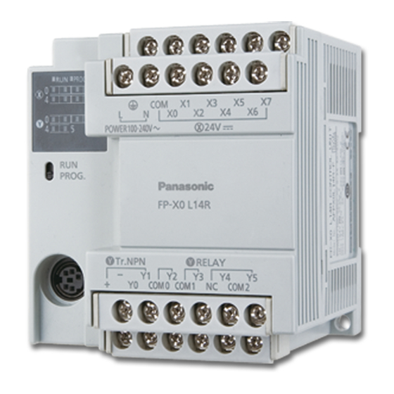
FP-X0 L14R
User manual
Panasonic FP-X0 L14R User Manual
Hide thumbs
1
2
Table Of Contents
3
4
5
6
7
8
9
10
11
12
13
14
15
16
17
18
19
20
21
22
23
24
25
26
27
28
29
30
31
32
33
34
35
36
37
38
39
40
41
42
43
44
45
46
47
48
49
50
51
52
53
54
55
56
57
58
59
60
61
62
63
64
65
66
67
68
69
70
71
72
73
74
75
76
77
78
79
80
81
82
83
84
85
86
87
88
89
90
91
92
93
94
95
96
97
98
99
100
101
102
103
104
105
106
107
108
109
110
111
112
113
114
115
116
117
118
119
120
121
122
123
124
125
126
127
128
129
130
131
132
133
134
135
136
137
138
139
140
141
142
143
144
145
146
147
148
149
150
151
152
153
154
155
156
157
158
159
160
161
162
163
164
165
166
167
168
169
170
171
172
173
174
175
176
177
178
179
180
181
182
183
184
185
186
187
188
189
190
191
192
193
194
195
196
197
198
199
200
201
202
203
204
205
206
207
208
209
210
211
212
213
214
215
216
217
218
219
220
221
222
223
224
225
226
227
228
229
230
231
232
233
234
235
236
237
238
239
240
241
242
243
244
245
246
247
248
249
250
251
252
253
254
255
256
257
258
259
260
261
262
263
264
265
266
267
268
269
270
271
272
273
274
275
276
277
278
279
280
281
282
283
284
285
286
287
288
289
290
page
of
290
Go
/
290
Contents
Table of Contents
Troubleshooting
Bookmarks
Table of Contents
Table of Contents
Before You Start
Programming Tool Restrictions
1 Unit Types and Restrictions
Unit Types
Restrictions on Unit Combinations
Programming Tools
2 Specifications and Functions of Control Unit
Parts and Functions
Power Supply Specifications
Input/Output Specifications
Analog Input Specifications (for L40 and L60 Types)
Terminal Layout
3 Specifications of Expansion Units and Expansion FP0 Adapter
FP-X Expansion Units
FP-X Expansion FP0 Adapter
4 I/O Allocation
I/O Allocation
I/O Allocation of FP-X0 Control Unit
FP-X Expansion Unit I/O Allocation
Allocation of FP0/FP0R Expansion Unit
5 Installation and Wiring
Installation
Expansion Method
Power Supply
Wiring of Input and Output
Wiring of Terminal Block
Setting and Wiring of COM Port (RS485)
Handling of Backup Battery (for L40 and L60 Types)
Safety Measures
6 Communication Functions
Functions and Types
Communicaton Port Type
Communication Specifications
Computer Link
General-Purpose Serial Communication
PC(PLC) Link Function (for L40MR and L60MR Types)
MODBUS RTU Communication (for L40MR and L60MR Types)
7 High-Speed Counter, Pulse Output and PWM Output Functions
Overview of each Functions
Function Specifications and Restricted Items
High-Speed Counter Function
Pulse Output Function
PWM Output Function
8 Security Functions
Password Protect Function
Upload Protection
Setting Function for FP Memory Loader
Table of Security Settings/Cancel
9 Other Functions
Clock/Calendar Function (for L40 and L60 Types)
Sampling Trance Function (for L40 and L60 Types)
Time Constant Processing
P13 (PICWT) Instruction
10 Self-Diagnostic and Troubleshooting
Self-Diagnostic Function
Troubleshooting
Operation Errors
11 Precautions During Programming
Use of Duplicated Output (Double Coil)
Instructions of Leading Edge Detection Method
Precautions for Programming
Rewrite Function During RUN
Processing During Forced Input and Output
12 Specifications
Table of Specifications
Relays, Memory Areas and Constants
13 Dimensions and Cable Specifications
Dimensions
Cable/Adapter Specifications
14 Appendix
System Registers / Special Internal Relays / Special Data Registers
Table of Basic Instructions
Table of High-Level Instructions
Table of Error Codes
MEWTOCOL-COM Communication Commands
Hexadecimal/Binary/Bcd
ASCII Codes
Advertisement
Quick Links
1
Programming Tools
2
Input/Output Specifications
Download this manual
Phone: 800.894.0412 - Fax: 888.723.4773 - Web: www.clrwtr.com - Email: info@clrwtr.com
Table of
Contents
Previous
Page
Next
Page
1
2
3
4
5
Advertisement
Table of Contents
Troubleshooting
Self-Diagnostic and Troubleshooting
175
Troubleshooting
177
Need help?
Do you have a question about the FP-X0 L14R and is the answer not in the manual?
Ask a question
Questions and answers
Related Manuals for Panasonic FP-X0 L14R
Controller Panasonic FP-E Programming Manual
Fp series (1334 pages)
Controller Panasonic FP-X0 L30R User Manual
(290 pages)
Controller Panasonic FP-X0 L40MR User Manual
(290 pages)
Controller Panasonic FP-X0 L60R User Manual
(290 pages)
Controller Panasonic FP-X0 L60MR User Manual
(290 pages)
Controller Panasonic FP-XH Series User Manual
Programmable controller (194 pages)
Controller Panasonic FP-XH Series User Manual
(138 pages)
Controller Panasonic FP0 Series Specifications
Fp0 series programmable controller (27 pages)
Controller Panasonic FP7 User Manual
Cpu unit. com port communication (109 pages)
Controller Panasonic FP7 Series User Manual
(192 pages)
Controller Panasonic FP7 User Manual
Positioning unit (275 pages)
Controller Panasonic FP7 Series Command Reference Manual
Cpu unit (1222 pages)
Controller Panasonic FP0R User Manual
(281 pages)
Controller Panasonic FPS Series User Manual
(332 pages)
Controller Panasonic FPG Series Technical Manual
Positioning unit (240 pages)
Controller Panasonic FP Series Technical Manual
(37 pages)
This manual is also suitable for:
Fp-x0 l40mr
Fp-x0 l60r
Fp-x0 l30r
Fp-x0 l60mr
Table of Contents
Save PDF
Print
Rename the bookmark
Delete bookmark?
Delete from my manuals?
Login
Sign In
OR
Sign in with Facebook
Sign in with Google
Upload manual
Upload from disk
Upload from URL


Need help?
Do you have a question about the FP-X0 L14R and is the answer not in the manual?
Questions and answers