
Related Manuals for Panasonic FP2 -C1A


Summary of Contents for Panasonic FP2 -C1A
- Page 1 PROGRAMMABLE CONTROLLER FP2 Analog Unit Manual FP2 Analog Unit Manual ARCT1F283E-4 04.10 Phone: 800.894.0412 - Fax: 888.723.4773 - Web: www.clrwtr.com - Email: info@clrwtr.com...
- Page 2 Safety Precautions Observe the following notices to ensure personal safety or to prevent accidents. To ensure that you use this product correctly, read this User’s Manual thoroughly before use. Make sure that you fully understand the product and information on safe. This manual uses two safety flags to indicate different levels of danger.
-
Page 3: Table Of Contents
Table of Contents Chapter 1 Functions and Restrictions Features ............1 - 3 Type of Unit . - Page 4 Table of Contents FP2 Analog Unit Chapter 6 Analog I/O Conversion Characteristics and Conversion Cycle Time Analog Input Conversion Characteristics ......6 - 3 Analog Output Conversion Characteristics .
- Page 5 FP2 Analog Unit Table of Contents Chapter 12 Sample Program for Analog Output Hold Setting 12.1 Output Hold Setting Basic Program (CPU Unit with Analog I/O) ..12 - 3 12.2 Output Hold (Any Value) Setting Program .
- Page 6 Precautions Before You Start About a similar manual For FP2 Analog Input Unit, there are two manuals, which is for FP2-AD8 (traditional type), and for FP2- AD8VI, AD8X and RTD (new type). The appropriate manual must be refered to use each product. (Two manuals for FP2 Analog Output Unit FP2-DA4 include the same contents.) Manual Name Manual No.
-
Page 7: Functions And Restrictions
Chapter 1 Functions and Restrictions Phone: 800.894.0412 - Fax: 888.723.4773 - Web: www.clrwtr.com - Email: info@clrwtr.com... - Page 8 Functions and Restrictions FP2 Analog Unit 1 - 2 Phone: 800.894.0412 - Fax: 888.723.4773 - Web: www.clrwtr.com - Email: info@clrwtr.com...
-
Page 9: Features
FP2 Analog Unit Functions and Restrictions Features Features Analog input 16 - bit high resolution High - speed A/D conversion (500µs to 90ms/channel) Multiple input range (12 types such as voltage, current, and temperature sensor) Temperature sensor (resistance thermometer device, thermocouple) direct input possible Analog output 12 - bit resolution... -
Page 10: Type Of Unit
Functions and Restrictions FP2 Analog Unit Type of Unit Type of Unit Name Function Order number CPU unit with analog I/O Analog input: 4 - channel FP2 - C1A Analog output: 1 - channel Analog input unit Analog input: 8 - channel FP2 - AD8 Analog output unit Analog output: 4 - channel... -
Page 11: Data Processing Functions
FP2 Analog Unit Functions and Restrictions 1.3 Data Processing Functions Data Processing Functions 1.3.1 Analog Input For analog input, there is the “General sampling function,” “Averaging function,” and “Offset changing function.” 1.3.1.1 General Sampling Function The analog input values are converted point by point and the digital values are stored in converted value area (input contact area). - Page 12 Functions and Restrictions FP2 Analog Unit Data Processing Functions 1.3.2 Analog Output For analog output, there is the “Analog output hold function.” 1.3.2.1 Analog Output Hold Function Non - hold, hold (final value during RUN mode), and hold (any value) for the analog output during the FP2 CPU unit PROG.
-
Page 13: Installation Restrictions
FP2 Analog Unit Functions and Restrictions 1.4 Installation Restrictions Installation Restrictions 1.4.1 CPU Unit with Analog I/O Can only be installed the CPU unit with analog I/O to the immediate right of the power supply unit on the CPU backplane (where the CPU unit is normally located). Cannot be installed the CPU unit with analog I/O on an expansion backplane. -
Page 14: Current Consumption
Functions and Restrictions FP2 Analog Unit Current Consumption Current Consumption The internal current consumption values for the FP2 analog units noted below. When the system is configured, the other units being used should be taken into consideration, and a power supply unit with a sufficient capacity should be used. Name Order number Current consumption (at 5 V DC) -
Page 15: Range Setting Restrictions
FP2 Analog Unit Functions and Restrictions 1.6 Range Setting Restrictions Range Setting Restrictions The following combinations cannot be specified within the same unit when setting the range for each channel using software. Range Voltage input Current in- Thermocou- R.T.D. input ple input ple input + / - 10V,... - Page 16 Functions and Restrictions FP2 Analog Unit Range Setting Restrictions 1 - 10 Phone: 800.894.0412 - Fax: 888.723.4773 - Web: www.clrwtr.com - Email: info@clrwtr.com...
-
Page 17: Parts And Specifications
Chapter 2 Parts and Specifications Phone: 800.894.0412 - Fax: 888.723.4773 - Web: www.clrwtr.com - Email: info@clrwtr.com... - Page 18 Parts and Specifications FP2 Analog Unit 2 - 2 Phone: 800.894.0412 - Fax: 888.723.4773 - Web: www.clrwtr.com - Email: info@clrwtr.com...
-
Page 19: Cpu Unit With Analog I/O (Fp2 - C1A)
FP2 Analog Unit Parts and Specifications CPU Unit with Analog I/O (FP2 - C1A) CPU Unit with Analog I/O (FP2 - C1A) ront Status indicator LEDs display the operating condition and error statuses. Mode selector is used to change the operation mode. Initialize/test switch is used to clear the errors, initializes the operation memory and set the test operation mode. - Page 20 Parts and Specifications FP2 Analog Unit CPU Unit with Analog I/O (FP2 - C1A) Analog output terminals For CPU unit with analog I/O, there are analog output terminals for channel 1. Terminals with a dot mark are not used; however, they are connected to the analog input circuit internally so do not connect anything to them.
-
Page 21: Analog Input Unit (Fp2 - Ad8)
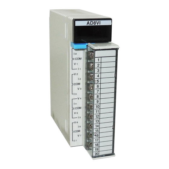
FP2 Analog Unit Parts and Specifications Analog Input Unit (FP2 - AD8) Analog Input Unit (FP2 - AD8) Analog input terminals For analog input unit, there are analog input terminals for channels 0 to 7. The terminal block can be removed to facilitate wiring. For detailed information section 3.1.2 Range setting switch... -
Page 22: Analog Output Unit (Fp2 - Da4)
Parts and Specifications FP2 Analog Unit Analog Output Unit (FP2 - DA4) Analog Output Unit (FP2 - DA4) Analog output terminals For analog output unit, there are analog outpput terminals for channels 0 to 3. Terminals with a dot mark are not used; however, they are connected to the analog input circuit internally so do not connect anything to them. -
Page 23: Chapter 3 Wiring
Chapter 3 Wiring Phone: 800.894.0412 - Fax: 888.723.4773 - Web: www.clrwtr.com - Email: info@clrwtr.com... - Page 24 Wiring FP2 Analog Unit 3 - 2 Phone: 800.894.0412 - Fax: 888.723.4773 - Web: www.clrwtr.com - Email: info@clrwtr.com...
-
Page 25: Suitable Terminals And Wires
FP2 Analog Unit Wiring Suitable Terminals and Wires Suitable Terminals and Wires 3.1.1 Suitable Terminals and Suitable Wires Suitable connection terminals M3 terminal screws are used for the terminals of analog input and output units. The following suitable connection terminals are recommended for the wiring to the terminals. Fork type terminal Round type terminal 6mm or less... - Page 26 Wiring FP2 Analog Unit Suitable Terminals and Wires 3.1.2 Wiring to Terminal Block Remove the terminal block before beginning the wiring operations. To remove the terminal block, push downward on the release lever located at the top of the terminal block.
-
Page 27: Wiring For Analog Input
FP2 Analog Unit Wiring Wiring for Analog Input Wiring for Analog Input 3.2.1 Voltage Input (±10V, 1 to 5V and ±100mV ranges) Input equipment Ch n Input terminals Shielded wire There is no ground terminal on the analog input units. 3.2.2 Current Input (±20mA and 4 to 20mA ranges) Input equipment... - Page 28 Wiring FP2 Analog Unit Wiring for Analog Input 3.2.4 R.T.D. (Resistance thermometer device) Input (Pt100, Pt1000) Three - wire R.T.D. (Resistance thermometer device) Ch n Input terminals There is no ground terminal on the analog input units 3.2.5 Precautions Regarding Analog Input Wiring For the wiring of “sections 3.2.1 and 3.2.2”...
-
Page 29: Wiring For Analog Output
FP2 Analog Unit Wiring 3.3 Wiring for Analog Output Wiring for Analog Output 3.3.1 Voltage Output (±10V range) Load equipment Ch n Output terminals Shielded wire 3.3.2 Current Output (0 to 20mA range) Load equipment Ch n Output terminals Shielded wire 3.3.3 Precautions Regarding Analog Output Wring For the analog output wiring, always use double - core twisted - pair shielded wires. -
Page 30: Emc Conformity
Wiring FP2 Analog Unit EMC Conformity EMC Conformity The FP2 CPU unit with analog I/O (FP2 - C1A), FP2 Analog input unit (FP2 - AD8) and FP2 Analog output unit (FP2 - DA4) conform to the European EMC standards EN50081 - 2: 1993, EN50082 - 2: 1995 as required by the European EMC Directive 89/336/EEC. -
Page 31: Setting The I/O Range And I/O Allocation
Chapter 4 Setting the I/O Range and I/O Allocation Phone: 800.894.0412 - Fax: 888.723.4773 - Web: www.clrwtr.com - Email: info@clrwtr.com... - Page 32 Setting the I/O Range and I/O Allocation FP2 Analog Unit 4 - 2 Phone: 800.894.0412 - Fax: 888.723.4773 - Web: www.clrwtr.com - Email: info@clrwtr.com...
-
Page 33: Setting The Input And Output Range
FP2 Analog Unit Setting the I/O Range and I/O Allocation Setting the Input and Output Range Setting the Input and Output Range Set the analog input and output range using the range setting switch on back side of unit. 4.1.1 Setting the Analog Input Range When setting the same range for the all the channels at once, you can only use the range setting switch. - Page 34 Setting the I/O Range and I/O Allocation FP2 Analog Unit Setting the Input and Output Range 4.1.2 Setting the Analog Output Range The analog output range setting can only be performed by the range setting switch. At the CPU unit with analog I/O, use range setting switch 6, and at the analog output units, use the range setting switches 1 to 4 to set the range for each channel.
-
Page 35: I/O Allocation
FP2 Analog Unit Setting the I/O Range and I/O Allocation I/O Allocation I/O Allocation During sequence program processing with the FP2, the analog input and output data is allocated to the I/O (X, Y) and refreshed. The I/O allocation for the analog input and output data is as shown in the table below. - Page 36 Setting the I/O Range and I/O Allocation FP2 Analog Unit I/O Allocation 4 - 6 Phone: 800.894.0412 - Fax: 888.723.4773 - Web: www.clrwtr.com - Email: info@clrwtr.com...
-
Page 37: Initial Settings
Chapter 5 Initial Settings Phone: 800.894.0412 - Fax: 888.723.4773 - Web: www.clrwtr.com - Email: info@clrwtr.com... - Page 38 Initial Settings FP2 Analog Unit 5 - 2 Phone: 800.894.0412 - Fax: 888.723.4773 - Web: www.clrwtr.com - Email: info@clrwtr.com...
-
Page 39: Analog Input Initial Settings
FP2 Analog Unit Initial Settings 5.1 Analog Input Initial Settings Analog Input Initial Settings Performs the initial settings for each channel of the analog input. The initial settings are set by the sequence program at the first scan at the start of operation. (The initial settings for the analog unit are enabled only for one time after operation start.) The items for the initial settings are given below. - Page 40 Initial Settings FP2 Analog Unit Analog Input Initial Settings 5.1.2 Analog Input Range Setting Specifies the input range code when setting input ranges for each input channel. (Set the range setting switch to ”Enable setting by software” and conversion will not be executed for that input channel if there is not input range code specification.) Program example: When ch0: ±10V, ch1: 1 to 5V, ch2: thermocouple K, and ch3: R.T.D.
- Page 41 FP2 Analog Unit Initial Settings 5.1 Analog Input Initial Settings 5.1.4 Analog Input Offset Changing Setting Specifies the digital value for the offset amount for each input channel. Between the range K - 2048 to K2047 can be set as the digital value for the offset amount; however, the range that can be obtained for the analog input conversion value that the offset is applied to is limited to between K - 32768 and K32767.
-
Page 42: Analog Output Initial Settings
Initial Settings FP2 Analog Unit Analog Output Initial Settings Analog Output Initial Settings Performs the initial settings for each channel of the analog output. The initial settings are set by sequence program at the first scan at the start of operation. (The initial settings for the analog unit are enabled only for one time after operation start.) The items for the initial settings are given below. -
Page 43: Chapter 6 Analog I/O Conversion Characteristics And Conversion Cycle Time
Chapter 6 Analog I/O Conversion Characteristics and Conversion Cycle Time Phone: 800.894.0412 - Fax: 888.723.4773 - Web: www.clrwtr.com - Email: info@clrwtr.com... - Page 44 Analog I/O Conversion Characteristics and Conversion Cycle Time FP2 Analog Unit 6 - 2 Phone: 800.894.0412 - Fax: 888.723.4773 - Web: www.clrwtr.com - Email: info@clrwtr.com...
-
Page 45: Analog Input Conversion Characteristics
FP2 Analog Unit Analog I/O Conversion Characteristics and Conversion Cycle Time Analog Input Conversion Characteristics Analog Input Conversion Characteristics The conversion characteristics of analog input range are shown below. - 10V to +10V DC +32767 +16383 - 10 - 16384 - 32768 Input range - 10V to +10V DC - 10... - Page 46 Analog I/O Conversion Characteristics and Conversion Cycle Time FP2 Analog Unit Analog Input Conversion Characteristics - 100mV to +100mV DC +32767 +16383 - 100 - 50 +100 (mV) - 16384 - 32768 Input range - 100mV to +100mV DC - 100 - 32768 - 75 - 24576...
- Page 47 FP2 Analog Unit Analog I/O Conversion Characteristics and Conversion Cycle Time Analog Input Conversion Characteristics 1V to 5V DC +13107 +6553 Input range 1V to 5V DC 3276 6553 9829 13107 If the input value exceeds the rated analog input range, the converted value becomes: Input value Converted value 1V or less...
- Page 48 Analog I/O Conversion Characteristics and Conversion Cycle Time FP2 Analog Unit Analog Input Conversion Characteristics - 20mA to +20mA DC +16383 +8191 - 20 - 10 (mA) - 8192 - 16384 Input range - 20mA to +20mA DC - 20 - 16384 - 15 - 12288...
- Page 49 FP2 Analog Unit Analog I/O Conversion Characteristics and Conversion Cycle Time Analog Input Conversion Characteristics 4mA to 20mA DC +13107 +6553 (mA) Input range 4mA to 20mA DC 3276 6553 9828 13107 If the input value exceeds the rated analog input range, the converted value becomes: Input value Converted value 4mA or less...
- Page 50 Analog I/O Conversion Characteristics and Conversion Cycle Time FP2 Analog Unit Analog Input Conversion Characteristics Thermocouple (S, J, K, T, R) Thermocouple S,R 15000 10000 Thermocouple K 7500 Thermocouple J 3500 Thermocouple T - 40 - 50 - 200 Thermocouple S ( C) Thermocouple R 1000...
- Page 51 FP2 Analog Unit Analog I/O Conversion Characteristics and Conversion Cycle Time Analog Input Conversion Characteristics If the input value exceeds the rated analog input range, the converted value becomes: Range Input value Converted value Thermocouple S - 400 - 40 C or less (*) +15000 +1500...
- Page 52 Analog I/O Conversion Characteristics and Conversion Cycle Time FP2 Analog Unit Analog Input Conversion Characteristics R.T.D. (Resistance thermometer device) (Pt100, Pt1000) Pt100 5000 Pt1000 1000 - 100 (°C) - 1000 Pt100 Pt1000 R.T.D. Pt100 R.T.D. Pt1000 °C °C - 100 - 1000 - 100 - 1000...
-
Page 53: Analog Output Conversion Characteristics
FP2 Analog Unit Analog I/O Conversion Characteristics and Conversion Cycle Time Analog Output Conversion Characteristics Analog Output Conversion Characteristics The conversion characteristics of analog output range are shown below. 10V to +10V DC - 2048 - 1024 +1023 +2047 - 10 Output range - 10V to +10V DC - 10 - 2048... - Page 54 Analog I/O Conversion Characteristics and Conversion Cycle Time FP2 Analog Unit Analog Output Conversion Characteristics 0mA to 20mA DC (mA) +2047 +4095 Output range 0mA to 20mA DC 4095 17.5 3580 3069 12.5 2558 2047 1534 1023 If the input value exceeds the rated digital input range, the analog output value becomes: Digital input value Analog output value - 1 or less...
-
Page 55: Analog Input And Output Conversion Cycle Time
FP2 Analog Unit Analog I/O Conversion Characteristics and Conversion Cycle Time Analog Input and Output Conversion Cycle Time Analog Input and Output Conversion Cycle Time 6.3.1 Analog Input Conversion Cycle Time When setting the range for each analog input channel, the conversion cycle time of the channel you want can be calculated by the formula below. - Page 56 Analog I/O Conversion Characteristics and Conversion Cycle Time FP2 Analog Unit Analog Input and Output Conversion Cycle Time Example of conversion cycle time calculation 2 Ch0 thermocouple K Ch1 thermocouple J ± Number of input channels used: n1 = 5 Ch3 thermocouple J Number of gain types: n2 = 2 Ch4 not used...
-
Page 57: Procedure For Handling Analog Unit
Chapter 7 Procedure for Handling Analog Unit Phone: 800.894.0412 - Fax: 888.723.4773 - Web: www.clrwtr.com - Email: info@clrwtr.com... - Page 58 Procedure for Handling Analog Unit FP2 Analog Unit 7 - 2 Phone: 800.894.0412 - Fax: 888.723.4773 - Web: www.clrwtr.com - Email: info@clrwtr.com...
-
Page 59: Outline Of Procedure For Handling Analog Unit
FP2 Analog Unit Procedure for Handling Analog Unit 7.1 Outline of Procedure for Handling Analog Unit Outline of Procedure for Handling Analog Unit The procedure for handling the FP2 analog unit is as follows. Procedure: Setting the analog input and output range Set the range using the range setting switch on back side of unit. -
Page 60: Reading The Analog Input Data
Procedure for Handling Analog Unit FP2 Analog Unit Reading the Analog Input Data Reading the Analog Input Data During sequence program processing with the FP2, the analog input data is allocated to the general input (X) and refreshed. In other words, the analog input conversion data is automatically refreshed and stored from the analog input circuit to the FP2 input relay area. -
Page 61: Writing The Analog Output Data
FP2 Analog Unit Procedure for Handling Analog Unit 7.3 Writing the Analog Output Data Writing the Analog Output Data During sequence program processing with the FP2, the analog output data is allocated to the general output (Y) and refreshed. The analog output data is automatically refreshed and written from the FP2 output relay area to the analog output circuit. - Page 62 Procedure for Handling Analog Unit FP2 Analog Unit Writing the Analog Output Data 7 - 6 Phone: 800.894.0412 - Fax: 888.723.4773 - Web: www.clrwtr.com - Email: info@clrwtr.com...
-
Page 63: Sample Program For Analog Input
Chapter 8 Sample Program for Analog Input Phone: 800.894.0412 - Fax: 888.723.4773 - Web: www.clrwtr.com - Email: info@clrwtr.com... - Page 64 Sample Program for Analog Input FP2 Analog Unit 8 - 2 Phone: 800.894.0412 - Fax: 888.723.4773 - Web: www.clrwtr.com - Email: info@clrwtr.com...
-
Page 65: Basic Program (Cpu Unit With Analog I/O)
FP2 Analog Unit Sample Program for Analog Input Basic Program (CPU Unit with Analog I/O) Basic Program (CPU Unit with Analog I/O) Program outline Using ch 0 to ch 2 (set for no execution of input conversion processing) of the CPU unit with analog I/O, this program reads the analog input data to the data registers DT100 to DT102 using the preparation completion flag. - Page 66 Sample Program for Analog Input FP2 Analog Unit Basic Program (CPU Unit with Analog I/O) Sample program: R 9013 F0 MV H 111 DT 0 Initial ch 0 to ch 2 Execution of conversion setting execution processing setting for ch F151 WRT DT 0 K 16...
-
Page 67: Basic Program (Analog Input Unit)
FP2 Analog Unit Sample Program for Analog Input Basic Program (Analog Input Unit) Basic Program (Analog Input Unit) Program outline Using ch 0 to ch 5 (set for no execution of input conversion processing) of the analog input unit, this program reads the analog input data to the data registers DT100 to DT105 using the preparation completion flag. - Page 68 Sample Program for Analog Input FP2 Analog Unit Basic Program (Analog Input Unit) Sample program: R 9013 F0 MV H 1111 DT 0 Initial ch 0 to ch 3 Execution of conversion setting execution processing setting for ch F151 WRT DT 0 K 16 0 to ch 3 analog inputs...
-
Page 69: Scale Conversion Processing Program (Cpu Unit With Analog I/O)
FP2 Analog Unit Sample Program for Analog Input Scale Conversion Processing Program (CPU Unit with Analog I/O) Scale Conversion Processing Program (CPU Unit with Analog I/O) Program outline Using ch 0 to ch 2 (set for no execution of input conversion processing) of the CPU unit with analog I/O, this program reads the scale - converted* analog input data to the data registers DT104 and DT114 using the preparation completion flag. - Page 70 Sample Program for Analog Input FP2 Analog Unit Scale Conversion Processing Program (CPU Unit with Analog I/O) Shared memory Address 10 Preparation completion flag for ch 0 to ch 3 analog inputs No execution of conversion processing setting for ch 0 to ch 3 analog inputs Address 16 For detailed information section 14.3.1...
-
Page 71: Temperature Sensor Input Broken Wire Detection
FP2 Analog Unit Sample Program for Analog Input Temperature Sensor Input Broken Wire Detection Temperature Sensor Input Broken Wire Detection For the input channels of the thermocouple input range and R.T.D (resistance thermometer device) input range, you can detect broken wires in the input wiring for each channel. - Page 72 Sample Program for Analog Input FP2 Analog Unit Temperature Sensor Input Broken Wire Detection 8 - 10 Phone: 800.894.0412 - Fax: 888.723.4773 - Web: www.clrwtr.com - Email: info@clrwtr.com...
-
Page 73: Sample Program For Analog Output
Chapter 9 Sample Program for Analog Output Phone: 800.894.0412 - Fax: 888.723.4773 - Web: www.clrwtr.com - Email: info@clrwtr.com... - Page 74 Sample Program for Analog Output FP2 Analog Unit 9 - 2 Phone: 800.894.0412 - Fax: 888.723.4773 - Web: www.clrwtr.com - Email: info@clrwtr.com...
-
Page 75: Basic Program (Analog Output Unit)
FP2 Analog Unit Sample Program for Analog Output Basic Program (Analog Output Unit) Basic Program (Analog Output Unit) Program outline This program writes the output data stored in data registers DT100 and DT101 to the output relay areas WY0 and WY1, which correspond to the output channels ch 0 and ch 1 of the analog output unit set for the execution of conversion processing. - Page 76 Sample Program for Analog Output FP2 Analog Unit Basic Program (Analog Output Unit) Sample program: R 9013 F0 MV H 11 DT 0 Initial ch 0 and ch 1 Execution of conversion setting execution processing setting for ch F151 WRT K 0 DT 0 K 1 K 22 0 and ch 1 analog outputs...
-
Page 77: Chapter 10 Sample Program For Analog Input Average Processing Setting
Chapter 10 Sample Program for Analog Input Average Processing Setting Phone: 800.894.0412 - Fax: 888.723.4773 - Web: www.clrwtr.com - Email: info@clrwtr.com... - Page 78 Sample Program for Analog Input Average Processing Setting FP2 Analog Unit 10 - 2 Phone: 800.894.0412 - Fax: 888.723.4773 - Web: www.clrwtr.com - Email: info@clrwtr.com...
-
Page 79: Sample Program (Cpu Unit With Analog I/O)
FP2 Analog Unit Sample Program for Analog Input Average Processing Setting 10.1 Sample Program (CPU Unit with Analog I/O) 10.1 Sample Program (CPU Unit with Analog I/O) Program outline After averaging the analog input data for ch 0 to ch 2 (set for no execution of input conversion processing) of the CPU unit with analog I/O, this program reads the averages to the data registers DT100 to DT102 using the preparation completion flag. - Page 80 Sample Program for Analog Input Average Processing Setting FP2 Analog Unit 10.1 Sample Program (CPU Unit with Analog I/O) Sample program: R 9013 F0 MV H 111 DT 0 Initial Execution of conversion ch 0 and ch setting processing setting for ch 0 2 execution to ch 2 analog inputs F151 WRT K 0...
- Page 81 FP2 Analog Unit Sample Program for Analog Input Average Processing Setting 10.2 Sample Program (Analog Input Unit) 10.2 Sample Program (Analog Input Unit) Program outline After averaging the analog input data for ch 0 to ch 4 (set for no execution of input conversion processing) of the analog input unit, this program reads the averages to the data registers DT100 to DT104 using the preparation completion flag.
- Page 82 Sample Program for Analog Input Average Processing Setting FP2 Analog Unit 10.2 Sample Program (Analog Input Unit) Sample program: R 9013 F0 MV H 1111 DT 0 Execution of conversion Initial ch 0 to 3 processing setting for ch 0 to setting execution ch 3 analog inputs...
- Page 83 FP2 Analog Unit Sample Program for Analog Input Average Processing Setting 10.2 Sample Program (Analog Input Unit) F0 MV WX 0 DT 100 ch 0 ch 0 Input value ch 0 data preparation completion F0 MV WX 1 DT 101 ch 1 ch 1 Input value ch 1 data...
- Page 84 Sample Program for Analog Input Average Processing Setting FP2 Analog Unit 10.2 Sample Program (Analog Input Unit) 10 - 8 Phone: 800.894.0412 - Fax: 888.723.4773 - Web: www.clrwtr.com - Email: info@clrwtr.com...
-
Page 85: Sample Program (Cpu Unit With Analog I/O)
Chapter 11 Sample Program of Analog Input Offset Setting Phone: 800.894.0412 - Fax: 888.723.4773 - Web: www.clrwtr.com - Email: info@clrwtr.com... - Page 86 Sample Program of Analog Input Offset Setting FP2 Analog Unit 11 - 2 Phone: 800.894.0412 - Fax: 888.723.4773 - Web: www.clrwtr.com - Email: info@clrwtr.com...
- Page 87 FP2 Analog Unit Sample Program of Analog Input Offset Setting 11.1 Sample Program (CPU Unit with Analog I/O) 11.1 Sample Program (CPU Unit with Analog I/O) Program outline This program offsets the analog input data for ch 0 to ch 2 (set for no execution of input conversion processing) of the CPU unit with analog I/O by the set numerical amount only, and then reads it to the data registers DT100 to DT102 using the preparation completion flag.
- Page 88 Sample Program of Analog Input Offset Setting FP2 Analog Unit 11.1 Sample Program (CPU Unit with Analog I/O) Sample program: R 9013 F0 MV H 111 DT 0 Initial Execution of conversion ch 0 to 2 setting processing setting for ch execution 0 to ch 2 analog inputs F151 WRT K 0...
- Page 89 FP2 Analog Unit Sample Program of Analog Input Offset Setting 11.2 Sample Program (Analog Input Unit) 11.2 Sample Program (Analog Input Unit) Program outline This program offsets the analog input data for ch 0 to ch 4 (set for no execution of input conversion processing) of the analog input unit by the set numerical amount only, and then reads it to the data registers DT100 to DT104 using the preparation completion flag.
- Page 90 Sample Program of Analog Input Offset Setting FP2 Analog Unit 11.2 Sample Program (Analog Input Unit) Sample program: R 9013 F0 MV H 1111 DT 0 Initial Execution of conversion ch 0 to 3 setting processing setting for ch 0 execution to ch 3 analog inputs F151 WRT K 0...
- Page 91 FP2 Analog Unit Sample Program of Analog Input Offset Setting 11.2 Sample Program (Analog Input Unit) F0 MV WX 0 DT 100 ch 0 ch 0 Input value preparation completion F0 MV WX 1 DT 101 ch 1 ch 1 Input value preparation completion F0 MV...
- Page 92 Sample Program of Analog Input Offset Setting FP2 Analog Unit 11.2 Sample Program (Analog Input Unit) 11 - 8 Phone: 800.894.0412 - Fax: 888.723.4773 - Web: www.clrwtr.com - Email: info@clrwtr.com...
-
Page 93: Sample Program (Cpu Unit With Analog I/O)
Chapter 12 Sample Program for Analog Output Hold Setting Phone: 800.894.0412 - Fax: 888.723.4773 - Web: www.clrwtr.com - Email: info@clrwtr.com... - Page 94 Sample Program for Analog Output Hold Setting FP2 Analog Unit 12 - 2 Phone: 800.894.0412 - Fax: 888.723.4773 - Web: www.clrwtr.com - Email: info@clrwtr.com...
-
Page 95: Output Hold Setting Basic Program (Cpu Unit With Analog I/O)
FP2 Analog Unit Sample Program for Analog Output Hold Setting 12.1 Output Hold Setting Basic Program (CPU Unit with Analog I/O) 12.1 Output Hold Setting Basic Program (CPU Unit with Analog I/O) Program outline When switching from the RUN mode to the PROG. mode, this program holds the analog output at the final value of the RUN* mode according to the shared memory (address 38) setting. -
Page 96: Output Hold (Any Value) Setting Program
Sample Program for Analog Output Hold Setting FP2 Analog Unit 12.2 Output Hold (Any Value) Setting Program 12.2 Output Hold (Any Value) Setting Program 12.2.1 Basic Program (CPU Unit with Analog I/O) Program outline When switching from the RUN mode to the PROG. mode, this program holds the analog output at any desired value according to the shared memory (addresses 38 and 39) settings. - Page 97 FP2 Analog Unit Sample Program for Analog Output Hold Setting 12.2 Output Hold (Any Value) Setting Program 12.2.2 Basic Program (Analog Output Unit) Program outline When switching from the RUN mode to the PROG. mode, this program holds the analog output at any desired value according to the shared memory (addresses 17 to 21) settings.
- Page 98 Sample Program for Analog Output Hold Setting FP2 Analog Unit 12.2 Output Hold (Any Value) Setting Program Sample program: R 9013 F0 MV DT 30 Initial Output hold setting setting F0 MV K 2047 DT 31 ch 0 any value F0 MV K 2047 DT 32...
- Page 99 Chapter 13 Troubleshooting Phone: 800.894.0412 - Fax: 888.723.4773 - Web: www.clrwtr.com - Email: info@clrwtr.com...
- Page 100 Troubleshooting FP2 Analog Unit 13 - 2 Phone: 800.894.0412 - Fax: 888.723.4773 - Web: www.clrwtr.com - Email: info@clrwtr.com...
-
Page 101: Problems Concerning The Analog Input
FP2 Analog Unit Troubleshooting 13.1 Problems Concerning the Analog Input 13.1 Problems Concerning the Analog Input Problem Remedy Analog input conversion value cannot Check the I/O allocation for the analog units. be read. Check the range settings. Check the settings for no execution of conversion processing (shared memory setting). -
Page 102: Problems Concerning The Analog Output
Troubleshooting FP2 Analog Unit 13.2 Problems Concerning the Analog Output 13.2 Problems Concerning the Analog Output Problem Remedy Proper analog output cannot be Make sure that the FP2 CPU unit is in RUN mode. obtained. Check the I/O allocation for the analog units. Check the range settings. - Page 103 Chapter 14 Specifications Phone: 800.894.0412 - Fax: 888.723.4773 - Web: www.clrwtr.com - Email: info@clrwtr.com...
- Page 104 Specifications FP2 Analog Unit 14 - 2 Phone: 800.894.0412 - Fax: 888.723.4773 - Web: www.clrwtr.com - Email: info@clrwtr.com...
-
Page 105: Table Of Performance Specifications
FP2 Analog Unit Specifications 14.1 Table of Performance Specifications 14.1 Table of Performance Specifications 14.1.1 General Specifications Item Specifications Ambient temperature 0 to 55°C/32 to 131°F Use the FP2 Analog output unit (FP2 - DA4) within the ranges given below. Output range Ambient operating temperature Current output range... - Page 106 Specifications FP2 Analog Unit 14.1 Table of Performance Specifications 14.1.2 Analog Input Specifications Item Specifications Number of input points 4 channels: FP2 - C1A, 8 channels: FP2 - AD8 Input range Voltage ±10V (1/65536) (resolution) l ti 1 to 5V (1/13107) ±100mV (1/65536) Current ±20mA (1/32768)
- Page 107 FP2 Analog Unit Specifications 14.1 Table of Performance Specifications Item Specifications Digital output Averaging 3 to 64 times/each channels processing Offset setting K - 2047 to K+2047/ each channels Broken wire sensing Only thermocouple range or R.T.D input range/each channels Input range change method All channels: By dip switch setting Each channels: By shared memory setting...
- Page 108 Specifications FP2 Analog Unit 14.1 Table of Performance Specifications 14.1.3 Analog Output Specifications Item Specifications Number of output points 1 channel (FP2 - C1A), 4 channels (FP2 - DA4) (* Note 1) Output range Voltage ±10V (K - 2048 to K+2047) (digital input) Current 0 to 20mA (K0 to K4095)
-
Page 109: Table Of Input/Output Contact Allocation
FP2 Analog Unit Specifications 14.2 Table of Input/Output Contact Allocation 14.2 Table of Input/Output Contact Allocation CPU unit with analog I/O Channel FP2 I/O Number Analog input Ch 0 WX0: X0 to XF Ch 1 WX1: X10 to X1F Ch 2 WX2: X20 to X2F Ch 3 WX3: X30 to X3F... -
Page 110: Table Of Shared Memory Area
Specifications FP2 Analog Unit 14.3 Table of Shared Memory Area 14.3 Table of Shared Memory Area In the FP2 CPU unit with analog I/O, analog input unit, and analog output unit, in addition to control of the analog input and output, shared memory that allows reading and writing by the sequence program is stored. - Page 111 FP2 Analog Unit Specifications 14.3 Table of Shared Memory Area Address 10 can only be written to after the first conversion is complete when the power is turned on. Addresses 18 to 21 can only be written to once using a user program after RUN.
- Page 112 Specifications FP2 Analog Unit 14.3 Table of Shared Memory Area 14.3.2 Shared Memory of Analog Input Unit Address Descriptions Initial value See section Preparation completion flag for analog input ch 0 to 7 H0000 14.4.1 No execution of conversion processing setting for analog input ch 0 to 3 H1111 14.4.2 No execution of conversion processing setting for analog input ch 4 to 7 H1111 Range setting for analog input ch 0 and 1...
- Page 113 FP2 Analog Unit Specifications 14.3 Table of Shared Memory Area Address 10 can only be written to after the first conversion is complete when the power is turned on. Addresses 18 to 21 can only be written to once using a user program after RUN.
- Page 114 Specifications FP2 Analog Unit 14.3 Table of Shared Memory Area 14.3.3 Shared Memory of Analog Output Unit Address Descriptions Initial value See section Output hold setting for analog output ch 0 to 3 H0000 14.5.1 Output hold (any value) data setting for analog output ch 0 K0000 14.5.2 Output hold (any value) data setting for analog output ch 1...
-
Page 115: Shared Memory For Analog Input Processing
FP2 Analog Unit Specifications 14.4 Shared Memory for Analog Input Processing 14.4 Shared Memory for Analog Input Processing 14.4.1 Analog Input Preparation Completion Flag (address 10) After the power is turned on and the first conversion is completed, the input channel where the conversion data preparation is completed is copied to the bits shown below. - Page 116 Specifications FP2 Analog Unit 14.4 Shared Memory for Analog Input Processing 14.4.3 Analog Input Range Setting (addresses 18 to 21) When setting the input range independently for each input channel, after setting the range setting switch to ”Enable setting by software,” the codes for the range settings shown below are set to addresses 18 to 21.
- Page 117 FP2 Analog Unit Specifications 14.4 Shared Memory for Analog Input Processing 14.4.4 Average Times Setting (addresses 22 to 29) Sets the number of times for average processing for each channel that executes average processing (range: 3 to 64 times). Bit position Address 22 Address 29 K3 to K64 (Default: K1)
- Page 118 Specifications FP2 Analog Unit 14.4 Shared Memory for Analog Input Processing 14.4.5 Offset Changing Setting (address 30 to 37) Sets the offset data for each channel that executes offset changing (range: - 2048 to +2047). Bit position Address 30 Address 37 K- 2048 to K2047 (Default: K0) Address 30:...
-
Page 119: Shared Memory Of Analog Output Processing
FP2 Analog Unit Specifications 14.5 Shared Memory of Analog Output Processing 14.5 Shared Memory of Analog Output Processing 14.5.1 Analog Output Hold Setting (CPU unit with analog I/O: address 38) (Analog output unit: address 17) Sets either the non - hold, hold (final value during RUN mode), or hold (any value) for the analog output during the FP2 CPU unit PROG. - Page 120 Specifications FP2 Analog Unit 14.5 Shared Memory of Analog Output Processing 14.5.3 No Execution of Analog Output Conversion Processing Setting (Analog output unit: address 22) Specifies the output channel where conversion processing is not executed. Bit position Address 22 ch 3 ch 2 ch 1 ch 0...
-
Page 121: Record Of Changes
FP2 Analog Unit Record of changes Record of changes Manual No. Date Description of Changes ARCT1F283E/ OCT. 1999 First edition ACG-M283E 2nd edition ARCT1F283E - 1/ DEC. 1999 Changes of section ACG-M283E - 1 - 1.4 Restrictions → 1.4 Installation Restrictions →...
Need help?
Do you have a question about the FP2 -C1A and is the answer not in the manual?
Questions and answers