Table of Contents
Advertisement
Quick Links
AC Servo Motor Driver
MINAS S-series
Operating Manual
Be sure give this instruction manual to the user.
• Thank you very much for your buying Panasonic AC Servo Motor Driver,A-series.
• Before use, read through this manual to ensure proper use. Keep this manual at an easily
accessible place so as to be referred anytime as necessary.
Advertisement
Table of Contents

Subscribe to Our Youtube Channel
Related Manuals for Panasonic MINAS S-series


Summary of Contents for Panasonic MINAS S-series
- Page 1 Operating Manual Be sure give this instruction manual to the user. • Thank you very much for your buying Panasonic AC Servo Motor Driver,A-series. • Before use, read through this manual to ensure proper use. Keep this manual at an easily...
-
Page 2: Table Of Contents
Table of Contents Before Use Safety Precautions ••••• 4 Parts Description ••••••••••• 12 Introduction ••••••••••••• 8 Amplifier ••••••••••••••••••••••••••••••••••••• 12 Motor ••••••••••••••••••••••••••••••••••••••••• 13 After Opening the Package •••••••••••••••• 8 Installation ••••••••••••••••• 14 Check the Model Number of Amplifier •••••••••••••••••• 8 Check the Model Number of Motor ••••••••••••••••••• 9 Amplifier •••••••••••••••••••••••••••••••••••••... - Page 3 Important Information Troubleshooting Protective Functions ••••••••••• 60 •••••••••••••••••••••••••••••• 68 Maintenance and After-Sale Service Inspections ••••••••••• 6 6 •••••••••••••••••••••• Back cover Appendixes Conformance to EC Directives and UL Standards ••••••••••• App. 2 Details of Parameters ••••••••••••• App. 16 Holding Brake ••••••••••••••••••••••••• App. 6 Optional Parts •••••••••••••••••••••••...
-
Page 4: Safety Precautions
Safety Precautions ( I m p o r t a n t ) Observe the following precautions in order to avoid injuries of opera- tors and other persons, and mechanical damages. The following DANGER and CAUTION symbols are used according to the level of dangers possibly occur- ring if you fail to observe the instructions or precautions indicated. - Page 5 DANGER D o n ' t t o u c h t h e r o t a t i n g Don't subject the product to part of the motor in motion. w a t e r s p l a s h , c o r r o s i v e gases, flammable gases and combustible things.
- Page 6 Safety Precautions ( I m p o r t a n t ) Caution Use the motor and Execute the trial operations amplifier in the specified with the motor fixed but combination. without motor load connected. Connecting a load to the motor is possible only after successful trial operation.
- Page 7 Caution Don't hold the cables or After recovery from the motor shaft when power failure, the transporting the motor. equipment may restart suddenly. Don't approach the equipment Failure to observe this Failure to observe this instruction could result in instruction could result injuries.
-
Page 8: Introduction
Introduction After Opening the Package • Make sure that the product is what you have ordered. • Check whether the product has been damaged or not during transportation. If the product is not correct, or it has been damaged, contact dealer or sales agent. Check the Model of Amplifier Name plate AC SERVO DRIVER... -
Page 9: Check The Model Number Of Motor
Check the Model of Motor Name plate T y p e CONT. TORQUE 0.64 Nm AC SERVO MOTOR RATING Rated output Serial No Model No. MUMS042A1A INS. CLASS B (TÜV) A (UL) INPUT 3ØAC IP65 Revolution rating CONNECTION RATED OUTPUT SER No. -
Page 10: Check The Combination Of Amplifier And Motor
Introduction Check the Combination of Amplifier and Motor The amplifier has been designed for use in combination with the specified motors only. Check the specifications (Series symbol, output rating, voltage rating and encoder type) of the motor you want to use. -10-... - Page 11 With the incremental type encoder: 2500P/r Power M o t o r Amplifier supply for Amplifier Output Revolution Encoder Series t y p e Voltage M o t o r t y p e amplifier rating rating type symbol **** 1-phase, MUDS3A1A1A Type1...
-
Page 12: Parts Description
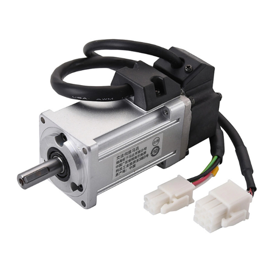
Parts Description Amplifier E x a m p l e : M U D S 0 2 3 A 1 A E x a m p l e : M U D S 0 4 2 A 1 A (3-phase, 200V 200W: Type 1) (1-phase, 200V 400W: Type 3) Status LED Alarm code LED... - Page 13 Motor Example: Super Low-Inertia Motor (MUMS Series, 400W) Encoder cable Motor cable Encoder Brake cable (Motor with electromag- Frame netic brake only ) Mounting bolt holes (4) Flange <Notes> For detailed information for each of motor types, see the drawings in the Appendix (App.48 &...
-
Page 14: Installation
Installation The amplifier and motor should be properly installed to avoid failures, mechanical damages and injuries. Amplifier Location • Indoors, where the amplifier is not subjected to rain water and direct sun beams. Note that the amplifier is not a waterproof structure. •... - Page 15 Mounting Direction and Space Requirements • Allow enough space to ensure enough cooling. • Install fans to provide a uniform distribution of temperature in the control box. The airflow of fan is more than 0.43m /min. And it should be located 10 cm away from the amplifier.
- Page 16 Installation Motor Location • Indoors, where the amplifier is not subjected to rain water and direct sun beams. • Avoid the place where the amplifier is subjected to corrosive gases, flammable gases, grinding liquids, oil mists, iron powders and cutting particles. •...
- Page 17 Cable: Stress Relieving • Make sure that the cables are not subjected to moments or vertical loads due to external bending forces or self-weight at the cable outlets or connections. • In case the motor is movable, secure the cable (proper one supplied together with the motor) to a stationery part (e.g.
-
Page 18: System Configuration And Wiring
System Configuration and Wiring General Wiring Diagram • Main Circuits Non-Fuse Breaker (NFB) Used to protect the power lines: overcurrent will shut off the circuit. Noise Filter (NF) Prevents the external noise from the power line, and reduces the effect of the noises gen- erated by the servo motor. - Page 19 Personal computer C o m m u n i c a t i o n STATUS c o n t r o l s o f t w a r e ALM CODE P A N A T E R M “ GAIN CN SER (to connect a PC or...
-
Page 20: List Of Available Components
System Configuration and Wiring List of Available Components Amplifier Circuit Mai n ci r cui t wi r e di a meter Required Power Noise Magnetic contactor breaker (L1 , L2, L3, Series Voltage Output (at the rated load) filter ( c o n t a c t s ) (rated current) U, V, W, E) - Page 21 For 3-phase 200VAC 3-phase 200V Noise filter 172167-1 172159-1 tyco Electronics AMP tyco Electronics AMP 5557-10R-210 White or yellow Black Green/yellow 5557-06R-210 Motor 12~24V COM – F o r 1 - p h a s e 1 0 0 V / 2 0 0 V Single-phase 100V or Single-phase 200V Noise filter...
-
Page 22: Main Circuits
System Configuration and Wiring Main Circuits Always ask to an electric engineer for wiring. Don't turn on the main power until the wiring and connectings are completed, to avoid electric shocks. Wiring Instructions • Make necessary connections. For wire diameter, see List of Available Components (page 20). •... -
Page 23: Cn Sig Connector
CN SIG Connector (For Encoder) Wiring Instructions The cable length between the amplifier and mo- tor should be max. 20 m. If you use a longer MSDS POWER ALARM Power GAIN cable, contact the dealer or sales agent. RS232C Separate these wiring min. 30 cm from the POWER main circuit wires. -
Page 24: Cn Ser Connector
System Configuration and Wiring CN SER Connector For RC232C communications Connect a personal computer to the amplifier with RS232C at 1:1, and use the communication control software "PANATERM “ " (Option). Operate "PANATERM “ " on the personal computer. Convenient functions of high operability can be o b t a i n e d s u c h a s m o n i t o r a n d p a r a m e t e r s e t t i n g a n d s e t t i n g c h a n g e a n d waveform graphic display. -
Page 25: For Controller
List of Available Components CN I/F Connector (For Controller) Wiring Instructions Place the peripheral devices such as the max. 3 m controller max. 3 m away from the amplifier. POWER MSDS Controller ALARM GAIN RS232C min. 30 cm Separate these wiring min. 30 cm from the main POWER Power circuit wires. - Page 26 System configutration and wiring Circuits Available for Typical Control Modes - 26 -...
- Page 27 - 27 -...
-
Page 28: Cn I/F Connector
System configuration and wiring CN I/F Connector Input Signals (Common) and their Functions P i n I / F Signal S y m b o l F u n c t i o n c i r c u i t C O M Å... - Page 29 P i n I / F Signal S y m b o l F u n c t i o n c i r c u i t Gain G A I N / The function differs depending on the control mode. s w i t c h i n g / ZEROSPD page 33...
- Page 30 System configuration and wiring P i n I / F Signal S y m b o l F u n c t i o n c i r c u i t CW overtravel C W L • If COM- is opened when the movable part of the inhibit machine has moved to CW exceeding the limit, the page 33...
- Page 31 Output Signals (Common) and their Functions P i n I / F Signal S y m b o l F u n c t i o n c i r c u i t Servo alarm A L M • This output (transistor) turns off, when the S O 1 detector detects an alarm.
- Page 32 System configuration and wiring P i n I / F Signal S y m b o l F u n c t i o n c i r c u i t A-phase output OA + • Provides differential outputs of the encoder signals P O 1 OA - (A, B and Z phases) that come from the divider...
- Page 33 CN I/F Connector Interface Circuit (Input Circuit) Connecting to 12~24V 1 COM+ 4.7kΩ sequence input signals Servo-ON or • Connect to a contact of switch and relay, or a tran- other input Relay sistor of an open collector output. • Use a switch or relay for micro current so that in- sufficient contact can be avoided.
- Page 34 System configuration and wiring Interface Circuit (Output Circuit) S O 1 Sequence output circuit Install as per the fig. shows without fail • This comprises a Darlington amplifier with an open collector. This is connected to a relay or photo coupler. •...
-
Page 35: Cn Mon Connector
P O 2 Open Collector Output Maximum rating: • Outputs Z-phase signals among those 30V, 50mA from the encoder. The outputs are non- insulated. • Receive these signal with high-speed photo coupler at controller side, since these Z-phase signal width is normally narrow. -
Page 36: Parameter Setting
Parameter Setting O v e r v i e w The servo amplifier has various parameters that are used for adjusting or set- ting the features or functions of the amplifier. This section describes the pur- pose and functions of these parameters. Understanding these parameters is essential for obtaining the best, application-specific operation of the amplifier. - Page 37 Parameters for Selecting Function Parameter Parameter description R a n g e D e f a u l t U n i t Pr** Åñ0 0 0 ~ 15 ------ A x i s a d d r e s s Åñ0 1 ----- ------...
- Page 38 Parameter Setting Parameters for Defining the Real Time Auto Gain Tuning Parameter No. Parameter description Range Default Unit (Pr**) Åñ2 0 ~ 10000 1 0 0 Inertia ratio Åñ2 0 ~ 3 ----- Real time auto tuning set-up Åñ2 0 ~ 9 ----- Machine stiffness at auto tuning Åñ2...
- Page 39 Parameters for Position Control Parameter No. Parameter description Range Default Unit (Pr**) 1 ~ 4 ----- Command pulse multiplier set-up 0 ~ 3 ----- Command pulse logic inversion 0 ~ 3 ----- Command pulse input mode set-up ----- (Internal use) 1 ~ 16384 2 5 0 0 -----...
-
Page 40: Setting The Parameters
Setting the Parameters Parameters for Sequence Parameter No Parameter description Range Default Unit Åñ6 0 ~ 32767 Pulse In-position range Åñ6 0 ~ 10000 r/min Zero speed Åñ6 0 ~ 10000 1 0 0 0 r/min A t - s p e e d Åñ6 0 ~ 32767 1 8 7 5... -
Page 41: Overview Of Panaterm
Setting the Parameters • You can set the Parameters with your personal computer with the S-series communication software PANATERM “ . <Notes> For the use of PANATERM “ for parameter handling, see the instruction manual of the soft- ware. Overview of PANATERM “ You can conduct the following operations using PANATERM “... - Page 42 Setting the Parameters Installing PANATERM on a hard disc “ <Notes> 1. The memory capacity of the hard disc should be 15MB or more. Prepare OS of Windows “ 95 o r W i n d o w s “ 9 8 . 2.
- Page 43 S t a r t i n g P A N A T E R M “ <Notes> 1. Once you install PANATERM “ on your hard disc, you do not have to install it again for next use. 2. Before using PANATERM “ , the amplifier, power supply, motor and encoder should be connected.
-
Page 44: Motor
Trial Run Inspections before Trial Run 1) Inspecting the wiring • Make sure that all wire connections (especially main power and motor output ) are correct. • Make sure that there is no short, and earth wires are properly connected. •... -
Page 45: Cn I/F Connected
Operation with CN I/F Connected 1) Connect CN I/F. 2) Connect the control signal (COM+/-) to the power supply (12 to 24V DC). 3) Turn the main power (amplifier) ON. 4) Check the defaults of the parameters. Control mode setting (Pr2 value: 0). 5) Connect between SRV-ON (CN I/F pin 2) and COM- (CN I/F pin 13) to make Servo-On active. - Page 46 Trial Run Set-up of motor speed and input pulse frequency Input pulse Motor P r 4 A Pr 46 frequency speed Pr 4B (pps) (r/min) 2 5 0 0 P / r 10000 500k 3000 10000 2 5 0 k 3 0 0 0 10000 5 0 0 0...
- Page 47 Test Run at Internal Velocity Control Mode Select the internal velocity control mode (Pr02: 1) for the control mode. 2) Run with zero speed clamp input (ZEROSPD) (5 pin) switch close, and rotate the motor with the combination of the internal command speed selection INTSPD 1 (6 pin) and INTSPD 2 (4 pin). 3) Check the motor speed on the PANATERM “...
-
Page 48: Motor
Trial Run Fundamental Operations and LED Indications 1. Turn on the power. STATUS ALM CODE Power supply GAIN CN POWER POWER MOTOR Motor - 48 -... - Page 49 2.Check LED status. LED color Meaning Green Main power is on. Amplifier power is on. Orange Flashing when warning occurs. (Overload, excessive regenerative energy) Alarm Make sure that the alarm code LED is not flashing. (Under the normal operation, the alarm indicator is OFF.) This indicator will start flashing when an alarm occurs.
-
Page 50: Adjustments
A d j u s t m e n t s Purposes of Gain Adjustment In case of the servo motor, the motor is required to act per any command without any time delay, or without missing any commands. To ensure this, gain adjustment is necessary. - Page 51 Applicability of Automatic Adjustment I t e m C o n d i t i o n s Load inertia • Must be at least three times as large as the motor inertia, but not greater than 20 times. • Must not fluctuate much L o a d •...
-
Page 52: How To Adjust Gain
A d j u s t m e n t s How to Adjust Gain Start · Adjust setting to value suitable for machine configuration. Turn gain adjustment rotary switch GAIN CW. · For table of rotary set values and machine configuration, see page 58. - Page 53 How to Use "Normal Auto-Gain" Tuning Automatic tuning is available when the gain adjustment rotary switch GAIN is set to "0" position only. 1) Start PANATERM “ , and click on "Auto tuning" in the window menu to open the automatic tuning screen.
-
Page 54: Auto-Gain" Tuning
A d j u s t m e n t s How to Use "Real Time Auto-Gain" Tuning Automatic tuning is available when the gain adjustment rotary switch GAIN is set to "0" position only. 1) Start PANATERM , and go to Parameter Set-up Mode. “... -
Page 55: How To Adjust Gain Manually
How to Adjust Gain Manually Before Adjustment You may adjust the gains by viewing or hearing the motions and sound of the machine during operation. But, to adjust the gains more quickly and precisely, you can obtain quicker and secure adjustment by analog wave form monitoring. 1. - Page 56 A d j u s t m e n t s How to Adjust the Gain at Position Control Mode 1) Input the inertia ratio of Pr20. For horizontal axis, take measurements on the basis of "Normal auto tuning". For vertical axis, obtain values through calculations. 2) Conduct adjustments with the parameters shown in the following table taken as guidance values.
- Page 57 How to improve the response further You can manually adjust the 2nd gain. With the 2nd gain adjustment, you can expect quicker response. <Example> When you want to reduce the noise produced during the stopping (servo-locking), you set the lower gain after the motor stops. Commanded Action speed...
-
Page 58: Gain Tuning Using
A d j u s t m e n t s Gain Tuning Using Gain Adjustment Rotary Switch Set the rotary switch depending on m a c h i n e c o n f i g u r a t i o n . T h e n w h i l e For increasing gain checking movement of machine, in- crease the rotary switch value one... -
Page 59: Resonance
To reduce the mechanical resonance If the machine is not stiff, vibration and noise may be generated due to the resonance by shaft torsion, and you mey not be able to set-up the higher gains. You can suppress the resonance by 2 types of the filters. 1 . -
Page 60: Protective Functions
Protective Functions What are the Protective Functions? The amplifier has various protective functions. When one of the protections is activated, the motor trips according to the timing chart shown in "Error Handling" in Appendix, and the Servo Alarm Output (ALM) is turned off. Actions to be taken after trip events •... - Page 61 Protective Functions: Causes and Corrections Alarm Protection C a u s e C o u n t e r m e a s u r e s Code No. Undervoltage Measure the terminal-to-terminal volt- The P-N voltage of the main power age (between L1, L2 and L3).
- Page 62 Protective Functions Protection C a u s e C o u n t e r m e a s u r e s *Overcurrent The current flowing in the converter is larger than the specified value. error 1) The amplifier failed (due to defective 1) Disconnect the motor wires, and enter circuits or IGBT parts).
- Page 63 Alarm Protection C a u s e C o u n t e r m e a s u r e s Code No. Overload protection is activated via Check on waveform graphic screen of Overload the specified time limiting operation P A N A T E R M w h e t h e r t h e t o r q u e “...
- Page 64 Protective Functions Alarm C a u s e C o u n t e r m e a s u r e s Protection Code No. * Encoder A/ No encoder A- and B-phase pulse is de- Correct the encoder wiring per the wiring tected.
- Page 65 Alarm Protection C a u s e C o u n t e r m e a s u r e s CodeNo. Error counter The value of the position error counter is Check that the motor operates per the over flow o v e r 2 ( 1 3 4 2 1 7 7 2 8 ) .
-
Page 66: Maintenance And Inspections
Maintenance and Inspections Å E Routine maintenance and inspections are essential for proper and satisfactory op- eration of the amplifier and motor. Notes to Maintenance/Inspections Personnel 1)Power-on/off operations should be done by the operators themselves. 2)For a while after power off, the internal circuits is kept charged at higher voltage. Inspections should be done a while (about 10 minutes), after the power is turned off and the LED lamp on the panel is extinguished. - Page 67 Replacement Guidance Parts replacement cycles depend on the actual operating conditions and how the equipment has been used. Defective parts should be replaced or repaired immediately. Dismantling for inspections or repairs should be done by our company (or our sales agents). P r o h i b i t e d Standard replacement Equipment...
- Page 68 Troubleshooting The motor does not rotate. [ C h e c k P o i n t s ] The status LED indicator turned red or orange? The LED indicator flashing? Parameter values correct? The voltage of the power is correct? STATUS ALM CODE Is the power fed?
- Page 69 The motor does not rotate. C o u n t e r m e a s u r e s C a t e g o r y C a u s e s Parameters The control mode selected is not Check the value of Pr02 (control mode set-up).
- Page 70 Troubleshooting The rotation is not smooth. C a t e g o r y C a u s e s C o u n t e r m e a s u r e s A d j u s t m e n t The gains are not appropriate.
- Page 71 Positioning accuracy is bad. C a t e g o r y C a u s e s C o u n t e r m e a s u r e s S y s t e m Count the number of feedback pulses on the monitor Position commands (amount of command pulses) are not cor- screen of PANATERM...
- Page 72 Troubleshooting The initial (home) position varies. C a t e g o r y C a u s e s C o u n t e r m e a s u r e s S y s t e m W h e n c a l c u l a t i n g t h e i n i t i a l Check that the Z-phase accords to the center of ( h o m e ) p o s i t i o n , t h e Z - p h a s e...
- Page 73 The motor produces an abnormal sound and/or vibration. C a t e g o r y C a u s e s C o u n t e r m e a s u r e s A d j u s t m e n t The gains are too large.
- Page 74 Troubleshooting Overshoot or undershoot The motor overheats (burnt) C a t e g o r y C a u s e s C o u n t e r m e a s u r e s A d j u s t m e n t Gains are not correct.
-
Page 75: Appendixes
Appendixes Conform to EC Directives and UL Standards App. 2 ○ ○ ○ ○ ○ ○ ○ Holding brake App. 6 ○ ○ ○ ○ ○ ○ ○ ○ ○ ○ ○ ○ ○ ○ ○ ○ ○ ○ ○ ○... -
Page 76: Conformance To Ec Directives And Ul Standards
Conformance to EC Directives and UL Standards EC Directives The EC Directives apply to all such electronic products as those having specific functions and directly sold to general consumers in EU countries. These products are required to meet the EU unified standards and to be furnished with CE Marking. - Page 77 Peripheral Equipment Environment The servo amplifier should be used under Contamination Level 2 or 1 specified by IEC60664- 1 (housing the amplifier in an IP54 control box). Control box Controller Insulated power for interface CN–I/F AC servo amplifier Noise filter for Noise filter for signal lines signal lines...
- Page 78 Conformance to EC Directives and UL Standards Surge Absorber Install a surge absorber at the primary side of the noise filter. <Notes> When performing a voltage-resisting test, remove the surge absorber. Otherwise the ab- sorber may be damaged. Install noise filters. Install noise filters (specially designed for signal wires) for all cables (power, motor, encoder and interface wires).
- Page 79 Install noise filfers Optional Part No. Manufacturer's Product No. Manufacturer 39 1 DVOP1460 ZCAT3035-1330 TDK Corporation 34 1 Weight: 62.8 g Noise Filter Optional Part No. Manufacturer's Product No. Manufacturer DVOP1441 3SUP-A10H-ER-4 Okaya Electric Industries Co., Ltd. 3SUP-A30H-ER-4 DVOP1442 A 4.0 H 1.5 B 1.5 I 1.5...
-
Page 80: Holding Brake
Holding brake The brake is to hold the work (movable part coupled to a vertical motor axis) to prevent it from falling by gravity in case the servo power is lost. <Caution> The holding brake is to hold the work, not stop its motion. Never use the brake for decelerating and stopping the machine. - Page 81 BRK-OFF Signal • See Timing Chart describing the timing of issuing BRK-OFF signal, e.g. to release the brake after power-on, and activate the brake in case a servo-off/ alarm occurs during the operation of the motor. • The timing (delay) of deactivating BRK-OFF signal (i.e. activating the brake) after the motor is freed into a non-excited status in case of Servo-OFF or alarm event can be adjusted by using Pr6B (brake output delay time set-up at motor in motion).
-
Page 82: Dynamic Brake
Dynamic Brake (DB) The amplifier has a dynamic brake for emergency use. Observe the following precautions. <Notes> 1. The dynamic brake should be used for emergency stop only. Do not start or stop the motor by switching servo-on signal on or off. Otherwise, dynamic brake circuit may be broken. - Page 83 Options of the operation through deceleration and stop by turning on Servo-OFF (Pr69) Operating conditions Sequence Position at Servo-OFF (Pr69) During deceleration After stop error counter Pr69 Clear Free run Free run Free run Free run Hold Free run Free run Free run Free run Options of the operation through deceleration and stop by turning on a protective function (Pr68)
-
Page 84: Timing Chart
Timing Chart After Power ON (receiving Servo-ON signal) Internal control power approx. 700 ms Main power control Dynamic brake Activated (braking) Released Motor energized Not energized Energized approx. approx. 10ms 50 ms Brake release (BRK-OFF) Operation (OFF) Released (ON) approx. 2 ms Internal reset Reset Released... - Page 85 After an Alarm event (during Servo-ON) Alarm Error (alarmed) Normal Dynamic brake Operation (braking) 2 approx.1 to 5 ms Not energized Motor energized Energized Servo alarm Alarm Not alarm (ALM) Set by Pr6B Brake release Operation (OFF) Released (ON) (BRK-OFF) t1 1 approx.
- Page 86 Timing Chart After an Alarm is cleared (during Servo-ON) 120 ms or more Alarm clear Entry of Clear signal (A-CLR) Dynamic brake Operation (braking) Released Not energized approx, 50 ms Motor energized Energized approx, 10 ms Brake release Operation (OFF) Released (ON) (BRK-OFF) Servo alarm...
- Page 87 Servo-ON/OFF operation when the motor is in operation With Servo-ON entered Servo-ON Servo-OFF Servo-ON (SRV-ON) Dynamic brake Braking Released Not energized Motor energized approx. 50 ms Energized approx. 10 ms Brake release Operation (OFF) Released (ON) (BRK-OFF) Servo-ON becomes active about 50ms after the motor speed becomes about 30 r/min or less.
- Page 88 Acceptable Loads on Output Axes Acceptable Loads on Output Axes Radial load (P) direction Thrust load (A and B) direction Unit: N (1 kgf = 9.8 N) Motor Motor output Acceptable during no operation Acceptable during operation series Radial load Thrust load Radial load Thrust load...
-
Page 89: Homing Operation (Precautions)
Homing operation (Precautions) In the returning operation to the home position using the controller, if the initialization signal (Z-phase signal from the encoder) is entered before the motor is not substantially decelerated (after the proximity sensor is activated), the motor may not stop at the required position. -
Page 90: Details Of Parameters
Details of Parameters Parameters for Function Selection Default setting is shown by [ ]. PrNo. P a r a m e t e r Value F u n c t i o n Axis address If multiple axes are used, it is necessary for the amplifier to identify the current axis accessed by [ 1 ] the host (e. - Page 91 PrNo. P a r a m e t e r Value F u n c t i o n Control mode set-up (continued) ( c o n t i n u e d ) * Example of 4 speeds operation using internal velocity command In addition to DIV/INTSPD1 and CL/INTSPD2, zero speed clamp input (ZEROSPD) and Servo-On input (SRV-ON) are required as the input to control start and stop of the motor.
- Page 92 Details of Parameters Default setting is shown by [ ]. PrNo. P a r a m e t e r Value F u n c t i o n O v e r t r a v e l 0 ~ 1 For linear motion or other similar motion, overtraveling of the work may cause input inhibit mechanical damages.
- Page 93 PrNo. P a r a m e t e r Value F u n c t i o n ZEROSPD 0 ~ 1 You can switch whether to enable or disable the zero i n p u t speed clamp input (ZEROSPD, CN I/F Pin 5). s e l e c t i o n Value Function of ZEROSPD input (Pin 5)
- Page 94 Details of Parameters PrNo. P a r a m e t e r Value F u n c t i o n Warning output 0 ~ 5 Y o u c a n d e f i n e t h e f u n c t i o n o f w a r n i n g o u t p u t selection (WARN: CN I/F 12-pin).
- Page 95 Parameters for Time Constants of Gains and Filters: Related to Real Time Auto Tuning PrNo. P a r a m e t e r Value F u n c t i o n U n i t 10 ~ 1 / s •...
- Page 96 Details of Parameters PrNo. P a r a m e t e r Value U n i t F u n c t i o n 2nd position 1 / s • This amplifier provides 2(two) sets (1st. and loop gain 2000 2nd.) of gain and time constant for position loop, [100]...
- Page 97 Parameters for real time gain tuning Default : [ PrNo. P a r a m e t e r Value U n i t F u n c t i o n Inertia ratio • You can set-up the ratio of load inertia to the 10000 motor's rotor inertia.
- Page 98 Details of Parameters Parameters for Switching to 2nd Gains Default : [ PrNo. P a r a m e t e r R a n g e U n i t F u n c t i o n d e s c r i p t i o n 0 ~ 1 ----- 2nd gain...
- Page 99 P a r a m e t e r R a n g e PrNo. U n i t F u n c t i o n d e s c r i p t i o n x 166 µs Position control •...
- Page 100 Details of Parameters Parameters for Position Control Default : [ PrNo. P a r a m e t e r R a n g e F u n c t i o n d e s c r i p t i o n 1 ~ 4 Command pulse You can set-up the multiplication when [quadrature pulse input]...
- Page 101 P a r a m e t e r R a n g e PrNo. F u n c t i o n d e s c r i p t i o n Maximum permissible frequency and minimum required time width of command pulse inputs (continued) I/F for inputting Maximum...
- Page 102 Details of Parameters Default : [ PrNo. P a r a m e t e r R a n g e F u n c t i o n d e s c r i p t i o n Parameters for Pulse Command Scaler (Pr46 through Pr4B) Numerator of 1st Pulse command scaling function (electronic gear)
- Page 103 P a r a m e t e r R a n g e PrNo. F u n c t i o n d e s c r i p t i o n You can select the numerator of the command scalar. *1 Select the 1st.
- Page 104 Details of Parameters PrNo. P a r a m e t e r R a n g e F u n c t i o n d e s c r i p t i o n 0 ~ 7 S m o o t h i n g This filter is a primary delay filter that is inserted after the scaling filter set-up...
- Page 105 Parameters for Velocity Control P a r a m e t e r R a n g e PrNo. F u n c t i o n d e s c r i p t i o n - 10000 1st internal You can set-up the internal command velocity of 1st - 4th speed s p e e d...
- Page 106 Details of Parameters PrNo. P a r a m e t e r R a n g e F u n c t i o n d e s c r i p t i o n You can add a quasi S-shaped acceleration/deceleration to the S-shaped velocity command, so that smooth operation can be obtained in a c c e l / d e c e l...
- Page 107 S e q u e n c e s Default : [ P a r a m e t e r R a n g e PrNo. F u n c t i o n d e s c r i p t i o n •...
- Page 108 Details of Parameters PrNo. P a r a m e t e r R a n g e F u n c t i o n d e s c r i p t i o n • You can set-up the output timing of at-speed signal (COIN: A t - s p e e d 10000 CN I/F 10 pin) by setting motor speed [r/min] in internal...
- Page 109 P a r a m e t e r R a n g e PrNo. F u n c t i o n d e s c r i p t i o n 0 ~ 1 DB inhibition at You can set-up the conditions for decelerating the motor overtravel limit after the over-travel limit input (CCWL: CNI/F Pin 9 or CWL:...
- Page 110 Details of Parameters Default: [ PrNo. P a r a m e t e r R a n g e F u n c t i o n d e s c r i p t i o n Defines the duration from OFF of the brake release signal (BRK- Mechanical Brake action OFF) (i.e.
- Page 111 P a r a m e t e r R a n g e PrNo. F u n c t i o n d e s c r i p t i o n E x t e r n a l Install an external regenerative discharge resistor (between P (5- 0 ~ 3 r e g e n e r a t i v e...
-
Page 112: Optional Parts
Optional Parts MINAS-S series Cables Fig. No. Motor type Cable Part No. 2 - 1 MUMS30 ~ 750W E n c o d e r c a b l e ( 2 5 0 0 P / r , 1 1 MFECAO**OEAA wires), incremental encoders 3 - 1... - Page 113 Connector for Monitor 1) Part No.DV0P2880 2) Components I t e m Manufacturer's Part No. Quantity Manufacturer R e m a r k s Connector (3P) 5 1 0 0 4 - 0 3 0 0 Molex For CN MON Connector pin 5 0 0 1 1 - 8 1 0 0 Incorporated...
- Page 114 Optional Parts Connector Kits for Motor and Encoder • Used for: MUMS 30W to 750W with a 2500-pulse, 11-wire incremental encoder 1) Part No. DVOP2900 2) Components I t e m Manufacturer's Part No. Q u a n t i t y Manufacturer R e m a r k s 1 0 1 2 0 - 3 0 0 0 V E...
- Page 115 5) Pin alignment of relay connector for encoder cable (NC) (NC) (NC) (NC) 6) Pin alignment of relay connector for motor cable 7) Pin alignment of connector for CN MOTOR (NC) (NC) < N o t e s > 1 . The table above shows the pins alignment, looking from the connector pin inserted direction of the connector.
- Page 116 Optional Parts Connector Kits for Host Control Equipment 1) Part No. DV0P0770 2) Components I t e m Manufacturer's Part No. Q u a n t i t y Manufacturer R e m a r k s 1 0 1 2 6 - 3 0 0 0 V E C o n n e c t o r SUMITOMO For CN I/F...
- Page 117 Interface Cables for controller connection 1) Part No. DVOP0800 Shell kit: 10326-52A0-008 Sumitomo 3M or the equivalents 2) Dimension 2000 12.7 Plug: 10126-3000VE 3) Wire table Sumitomo 3M or the equivalents Signal name Signal name Signal name Pin No. Wire color Pin No.
- Page 118 Optional Parts Communication Cables (for connection to personal computer) 1) Part No. DVOP1960 (for DOS/V) (78.74) 2) Part No. DVOP1160 (for PC98 series) (78.74) Communication Control Software PANATERM ® 1) Part No. DVOP2820 (English Version) 2) 3.5 inches Floppy Disks <...
- Page 119 External Regenerative Discharge Resistor Specifications P r o d u c t Part.No. n u m b e r R e s i s t a n c e Rated power Built-in thermal fuse operating temperature DV0P2890 4 5 M 0 3 50 Ω...
- Page 120 Optional Parts R e a c t o r Reactor Rated output Amplfier Voltage Part No. fig. 1 MUDS Single- 30W ~ 100W DVOP227 phase 100W 1 0 0 V 200W ~ 400W DVOP228 30W ~ 400W Single- DVOP220 100W ~ 400W phase (Mounting dimensions) 2 0 0 V...
-
Page 121: Recommended Parts
Recommended Parts Surge Absorber for Motor Brake M o t o r Surge absorber for brake MUMS30W ~ 750W • C-5A2 or Z15D151 Ishizuka Electronics Corpration • Recommended parts are those specified for measurement of the brake releasing time. Peripheral Equipment Manufacturers N o v e m b e r 2 0 0 0 M a n u f a c t u r e r / a g e n t T e l... -
Page 122: Dimensions
Dimensions M o t o r MUMS Series 30W ~ 750W Encoder wire dimension LH 3 0 W - 1 0 0 W 2 3 0 m m 2 0 0 W - 7 5 0 W 2 2 0 m m Model Output(W) LR mm(Inch) - Page 123 4-øLZ KWh9 Key way type (Dimentions incl. key) Weight(kg) 5 . 8 0 . 3 0 1 . 6 5 4 1 . 7 2 4 1 2 . 5 6 . 2 0 . 4 0 Depth4.5 0 . 5 0 8 .
- Page 124 Dimensions Amplifier Type 1 Weight: 0.7 kg unit: mm(Inch) Back panel mount type (Standard) 45(1.772) 120(4.724) 20(0.787) 4.1(0.161) 10(0.394) STATUS MSDS ALM CODE AC SERVO AMPLIFIER GAIN Model No. INPUT OUTPUT ENCODER Phase F.L.C Freq. Power SER.NO. 60/75˚C Wire Only Use Copper Conductors Only Refer to Manual for Wiring and Wire Size Refer to Manual for Over Load Protection...
- Page 125 Amplifier Type 2 Weight: 0.9 kg unit: mm(Inch) Back panel mount type (Standard) 60(2.362) 25(0.984) 120(4.724) 15(0.591) 20(0.787) 4.1(0.161) STATUS MSDS ALM CODE AC SERVO AMPLIFIER GAIN Model No. INPUT OUTPUT ENCODER Phase F.L.C Freq. Power 6 0 / 7 5 ° C W i r e O n l y SER.NO.
- Page 126 Dimensions Amplifier Type 3 eight: 1.2 kg unit: mm(Inch) Back panel mount type (Standard) 65(2.559) 2(0.079) 61(2.402) 32.5(1.280) 160(6.299) 15(0.591) 2.3(0.091) STATUS MSDS ALM CODE AC SERVO AMPLIFIER GAIN Model No. INPUT OUTPUT ENCODER Phase F.L.C Freq. Power 6 0 / 7 5 ° C W i r e O n l y SER.NO.
-
Page 127: Characteristics
C h a r a c t e r i s t i c s 53 - App. -
Page 128: Specifications
Specifications Gain Switching Conditions Position Control Mode Åú : the parameter valid, -: invalid) Parameters for position control Gain switching conditions Åñ1 Åñ2 Delay time L e v e l Hysteresis P r 3 1 Switching conditions Figure Pr32 Pr33 Pr34 Fixed to 1st gain -----... - Page 129 Speed command S Speed N delayed 2nd Gain Torque T Level Speed N Delay 1st Gain COIN delayed 2nd Gain Speed command S Level delayed 2nd Gain Speed N Position error Level delayed 2nd Gain < N o t e s > The figures above do not reflect the gain switching timing delay caused by hysteresis ( Pr34) .
- Page 130 Specifications 56 - App.
- Page 131 57 - App.
- Page 132 Specifications P o w e r + 10% Single-phase 100V system Single-phase, AC100 - 115V 50/60Hz - 15% + 10% Single-phase 200V system Single-phase, AC200 - 230V 50/60Hz - 15% + 10% 3-phase 200V system 3-phase, AC200 - 230V 50/60Hz - 15% Permissible frequency variation Max.
- Page 133 Electric Data Electric data of this product (Instruction Manual, CAD data) can be downloaded from the following web site. http://industrial.panasonic.com/ww/i_e/25000/motor_fa_e/motor_fa_e.html Memorandum (Fill in the blanks for convenience in case of inquiry or repair) MUDS Date of purchase Model No.
Need help?
Do you have a question about the MINAS S-series and is the answer not in the manual?
Questions and answers