Advertisement
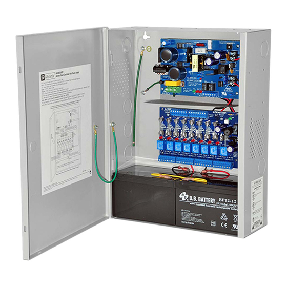
ACM Series
Access Power Controllers
with Power Supplies
Installation Guide
Models Include:
• AL400ULACM
- 12VDC @ 4 amp
or 24VDC @ 3 amp
- Fused Outputs
• AL1012ULACM
- 12VDC @ 10 amp.
- Fused Outputs
For a red enclosure add an "R" suffix to the part # e.g. AL1024ULACMR
Available from A1 Security Cameras
www.a1securitycameras.com email:sales@a1securitycameras.com
• AL600ULACM
- 12VDC or 24VDC @ 6 amp.
- Fused Outputs
• AL1024ULACM
- 24VDC @ 10 amp.
- Fused Outputs
Rev. 102512
Advertisement
Table of Contents

Subscribe to Our Youtube Channel
Related Manuals for Altronix AL400ULACM


Summary of Contents for Altronix AL400ULACM
- Page 1 ACM Series Access Power Controllers with Power Supplies Installation Guide Models Include: • AL400ULACM • AL600ULACM - 12VDC @ 4 amp - 12VDC or 24VDC @ 6 amp. or 24VDC @ 3 amp - Fused Outputs - Fused Outputs • AL1012ULACM •...
-
Page 2: Specifications
Fail-Secure modes. The FACP Interface enables Emergency Egress, Alarm Monitoring, or may be used to trigger other auxiliary devices. The fire alarm disconnect feature is individually selectable for any or all of the eight (8) outputs. ACM Series Configuration Reference Chart: UL 294 Altronix Corp. AL400ULACM 140 58th St. Brooklyn, NY 8 3.5A Yes 3.5A... -
Page 3: Installation Instructions
(pg. 8) 2. Set output voltage: AL400ULACM and AL600ULACM: set desired DC output voltage by setting switch SW1 to the appropriate position on the power supply board. AL1012ULACM is factory set at 12VDC and AL1024ULACM is factory set at 24VDC (Output Voltage and Stand-by Specification Charts below). -
Page 4: Maintenance
(b) Form “C” outputs: When form “C” outputs are desired the corresponding output fuse (1-8) must be removed. Connect negative (–) of the power supply directly to the locking device. Connect the positive (+) of the power supply to the terminal marked [C]. -
Page 5: Typical Application Diagram
Typical Application Diagram: Fig. 1 Fig. 1a Intact = Dry Input Normally Open (N.O.) Cut = Wet Input Door Releasing FACP Device Keypad Access Control Panel (Fire Alarm Control Panel) Output Fig. 1b FACP Dry Relay Form "C" Output IN GND IN GND IN GND IN GND... -
Page 6: Power Supply Board
OUTPUT 3 OUTPUT 4 OUTPUT 5 OUTPUT 6 OUTPUT 7 OUTPUT 8 DC Output to devices (power-limited for AL400ULACM, non power-limited for all other models*) Optional Rechargeable Optional Rechargeable Stand-by Battery Stand-by Battery CAUTION: Optional rechargeable stand-by batteries must match the power supply output voltage setting. - Page 7 L, N Connect 115VAC 60Hz to these terminals: L to hot, N to neutral. AL400ULACM - 12VDC @ 4 amp or 24VDC @ 3 amp to ACM8 board (power-limited). AL600ULACM - 12VDC/24VDC @ 6 amp to ACM8 board (non power-limited).
-
Page 8: Hookup Diagrams
Hook-Up Diagrams: Fig. 4 Polarity reversal input from FACP signaling circuit Fig. 3 Optional hook-up using two (2) isolated output (polarity is referenced in alarm condition): power supply inputs: CUT JUMPERS J1 AND J2 JUMPER FACP OUTPUT EOL ISOLATED POWER INPUT 12 OR 24 VAC OR VDC (ACM8 POWER) FROM FACP... - Page 9 AL1024ULACM Battery Size Calculation Worksheet: A. AL1024ULACM internal current consumption (stand-by) ___________________ 0.35 A B. Load current consumption (stand-by) ___________________ A C. Stand-by time required (Hours) ___________________ H D. Battery capacity required for stand-by (A+B)*C ___________________ AH E. AL1024ULACM internal power consumption (Alarm) ___________________ 0.35 A F.
-
Page 10: Enclosure Dimensions
Enclosure Dimensions (H x W x D approximate BC400) 15.5” x 12” x 4.5” (393.7mm x 304.8mm x 114.3mm) 1.5” 4.615” 4.615” 1.5” (38.1mm) (117.22mm) (117.22mm) (38.1mm) 1.75” (44.45mm) 1.375” (34.925mm) 1.125” (28.575mm) 12.23” 4.5” 4.5” (310.64mm) (114.3mm) (114.3mm) 1.25” 1.1”... - Page 11 Notes: ACM series - 11 Available from A1 Security Cameras www.a1securitycameras.com email:sales@a1securitycameras.com...
- Page 12 Notes: Altronix is not responsible for any typographical errors. 140 58th Street, Brooklyn, New York 11220 USA, 718-567-8181, fax: 718-567-9056 web site: www.altronix.com, e-mail: info@altronix.com, Lifetime Warranty, Made in U.S.A. MEMBER IIACM series J09O - 12 - ACM series Available from A1 Security Cameras...
Need help?
Do you have a question about the AL400ULACM and is the answer not in the manual?
Questions and answers