Table of Contents
Advertisement
Quick Links
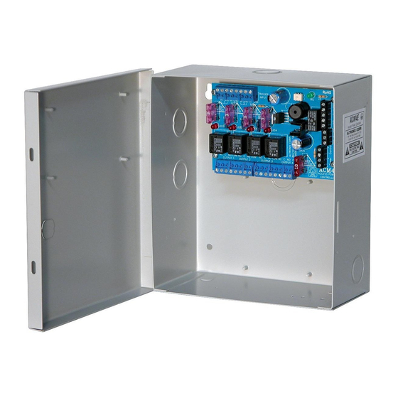
ACM4E Series
Access Power Controllers
Models Include:
ACM4E
- Four (4) Fuse Protected Outputs
ACM4CBE
- Four (4) PTC Protected Outputs
Installation Guide
Rev. 052419
Installing Company: _______________ Service Rep. Name: __________________________________
Address: _____________________________________________ Phone #: __________________
More than just power.
TM
Advertisement
Table of Contents

Related Manuals for Altronix ACM4E Series


Summary of Contents for Altronix ACM4E Series
- Page 1 ACM4E Series Access Power Controllers Models Include: ACM4E - Four (4) Fuse Protected Outputs ACM4CBE - Four (4) PTC Protected Outputs Installation Guide More than just power. Rev. 052419 Installing Company: _______________ Service Rep. Name: __________________________________ Address: _____________________________________________ Phone #: __________________...
- Page 2 Overview: Altronix ACM4E and ACM4CBE Access Power Controllers convert one (1) 12 to 24 volt AC or DC input into four (4) independently controlled fused or PTC protected outputs. These power outputs can be converted to dry form “C” contacts (ACM4E only). Outputs are activated by an open collector sink or normally open (NO) dry trigger input from an Access Control System, Card Reader, Keypad, Push Button, PIR, etc.
- Page 3 Installation Instructions: 1. Mount unit in the desired location. Mark and predrill holes in the wall to line up with the top two keyholes in the enclosure. Install two upper fasteners and screws in the wall with the screw heads protruding. Place the enclosure’s upper keyholes over the two upper screws;...
- Page 4 7. Installation of tamper switch (Not Included): Mount UL Listed tamper switch (Altronix Model TS112 or equivalent) at the top of the enclosure. Slide the tamper switch bracket onto the edge of the enclosure approximately 2” from the right side.
- Page 5 Typical Application Diagram: Fig. 1 Fig. 1a Keypad FACP Dry Form "C" Access Control Output Panel FACP (Fire Alarm Normally Open Control Panel) N.O. Door Output Releasing Device Relay SW1-SW4 TRIGGER INPUT FACP Interface Enabled IN GND IN GND IN GND IN GND FACP Interface Disabled LED1...
- Page 6 Hook-up Diagrams: Fig. 2 Optional hook-up using two (2) isolated power supply inputs: CUT JUMPERS J1 AND J2 ISOLATED POWER INPUT 12 OR 24VAC OR VDC (ACM4 POWER) ISOLATED POWER INPUT 12 OR 24VAC OR VDC J2 J1 (LOCK POWER) Fig.
- Page 7 Hook-up Diagrams (cont’d): Fig. 5 Normally Open FACP Latching trigger input with reset: (This output has not been evaluated by UL) N.O. TRIGGER INPUT N.C. RESET SWITCH JUMPER Fig. 6 Normally Closed - Non-Latching FACP trigger input: N.C. DRY TRIGGER INPUT JUMPER Fig.
- Page 8 (25.4mm) 5.25” (133.35mm) 1” 1” (25.4mm) (25.4mm) Altronix is not responsible for any typographical errors. 140 58th Street, Brooklyn, New York 11220 USA | phone: 718-567-8181 | fax: 718-567-9056 website: www.altronix.com | e-mail: info@altronix.com | Lifetime Warranty IIACM4E/ACM4CBE F25U MEMBER...
Need help?
Do you have a question about the ACM4E Series and is the answer not in the manual?
Questions and answers