Sign In
Upload
Download
Add to my manuals
Delete from my manuals
Share
URL of this page:
HTML Link:
Bookmark this page
Add
Manual will be automatically added to "My Manuals"
Print this page
×
Bookmark added
×
Added to my manuals
Manuals
Brands
Altronix Manuals
Controller
ACM4 Series
Installation manual
Altronix ACM4 Installation Manual
Sub-assembly
Hide thumbs
Also See for ACM4
:
Installation manual
(9 pages)
1
2
3
4
5
6
7
8
9
10
11
12
13
14
15
16
17
18
19
20
21
22
23
24
page
of
24
Go
/
24
Bookmarks
Advertisement
Quick Links
Download this manual
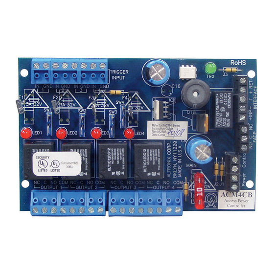
Sub-Assembly
Installation Guide
for Models:
ACM4
ACM4CB
ACM8
ACM8CB
MOM5
PD4UL
PD4ULCB
PD8UL
PD8ULCB
PD16W
PD16WCB
PDS8
PDS8CB
ACMS8
ACMS8CB
VR6
LINQ2
LINQ8PD*
LINQ8PDCB*
*not evaluated by UL
Rev. MS020119
SIGNALING
More than just power.
TM
Previous
Page
Next
Page
1
2
3
4
5
Advertisement
Need help?
Do you have a question about the ACM4 and is the answer not in the manual?
Ask a question
Questions and answers
Subscribe to Our Youtube Channel
Related Manuals for Altronix ACM4
Controller Altronix ACM4 Series Installation Manual
Ul listed sub-assembly access power controllers (9 pages)
Control Unit Altronix LINQ8PD Installation And Programming Manual
Network power distribution module (16 pages)
Power Supply Altronix eFlow104NK8QP Installation Manual
Networkable dual output power supply/charger (12 pages)
Controller Altronix ACMS8 Installation Manual
Sub-assembly access power (12 pages)
IP Access Controllers Altronix ACM8 Installation Manual
Access power controllers (9 pages)
Controller Altronix acm8cb Installation Manual
Acm8 series ul listed sub-assembly access power controllers (9 pages)
Control Unit Altronix LINQ LINQ8PD Series Installation And Programming Manual
Network power distribution modules (8 pages)
Control Unit Altronix LINQ2 Installation And Programming Manual
Two (2) port connectivity ethernet/network communications module (8 pages)
Control Unit Altronix MOM5 Installation Manual
Ul listed sub-assembly multi-output power distribution module (8 pages)
Power distribution unit Altronix PDS8CB User Manual
Dual input power distribution module (4 pages)
Controller Altronix VR6 Installation Manual
Voltage regulator (4 pages)
Control Unit Altronix MOM5 Installation Instructions
Multi output power distribution for acces control (4 pages)
Control Unit Altronix PD16WCB Quick Start Manual
Power distribution modules (2 pages)
Controller Altronix ACM Series Installation Manual
Access power controllers with power supplies (13 pages)
Controller Altronix AL400ULACM Installation Manual
Acm series access power with power supplies (13 pages)
Controller Altronix ACMJ Series Installation Manual
Access power controllers with power supplies (13 pages)
This manual is also suitable for:
Acm4cb
Acm8
Mom5
Acm8cb
Pd4ul
Pd8ul
...
Show all
Pd4ulcb
Pd8ulcb
Pd16w
Pd16wcb
Pds8
Pds8cb
Acms8
Acms8cb
Vr6
Linq2
Linq8pd
Linq8pdcb
Print
Rename the bookmark
Delete bookmark?
Delete from my manuals?
Login
Sign In
OR
Sign in with Facebook
Sign in with Google
Upload manual
Upload from disk
Upload from URL


Need help?
Do you have a question about the ACM4 and is the answer not in the manual?
Questions and answers