Advertisement
ACM Series
Access Power Controllers
with Power Supplies
Installation Guide
Models Include:
AL400ULACM
- 12VDC @ 4A
or 24VDC @ 3A.
- Fused Outputs
AL600ULACM
- 12VDC or 24VDC @ 6A.
- Fused Outputs
For a red enclosure add an "R" suffix to the part # e.g. AL1024ULACMR
Rev. 050819
AL1012ULACM
- 12VDC @ 10A.
- Fused Outputs
AL1024ULACM
- 24VDC @ 10A.
- Fused Outputs
More than just power.
TM
Advertisement
Table of Contents

Related Manuals for Altronix ACM Series


Summary of Contents for Altronix ACM Series
- Page 1 ACM Series Access Power Controllers with Power Supplies Installation Guide Models Include: AL400ULACM AL1012ULACM - 12VDC @ 4A - 12VDC @ 10A. or 24VDC @ 3A. - Fused Outputs - Fused Outputs AL600ULACM AL1024ULACM - 12VDC or 24VDC @ 6A.
-
Page 2: Output Voltage And Stand-By Specification Charts
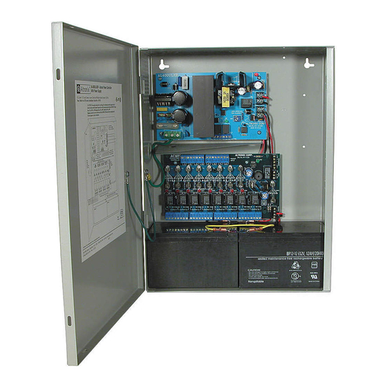
Overview: Altronix ACM Series units distribute and switch power to access control systems and accessories. They convert a 115VAC 60Hz input into eight (8) independently controlled 12VDC or 24VDC fuse protected outputs. These power outputs can be converted to dry form “C” contacts. Outputs are activated by an open collector sink or normally open (NO) dry trigger input from an Access Control System, Card Reader, Keypad, Push Button, PIR, etc. -
Page 3: Specifications
Input: Outputs (cont’d): • Power input 115VAC, 60Hz • Alarm output relay indicates that FACP input is (see ACM Series Power Supply Configuration triggered (form “C” contact rated @ 1A 28VDC, Reference Chart, pg. 2). not evaluated by UL). • ACM8 Power Input Options: •... - Page 4 When using DC power supplies polarity must be observed. When using AC power supplies polarity need not be observed (Fig. 1d, pg. 6). Note: For UL compliance the additional power supply must be power-limited, UL Listed for Access Control Systems and accessories. - 4 - ACM Series...
-
Page 5: Maintenance
FACP output circuit (Fig. 4 through 8, pgs. 8-9). FACP INTERFACE Form “C” relay contact rated @ 1A 28VDC for alarm reporting. NC, C, NO (This output has not been evaluated by UL). ACM Series - 5 -... -
Page 6: Typical Application Diagram
Battery Status Normal operating condition. Battery fail/low battery. ACM8 Access Power Controller LED 1 - LED 8 (Red) Output relay(s) energized. Output relay(s) de-energized. Trg (Green) FACP input triggered (alarm condition). FACP normal (non-alarm condition). - 6 - ACM Series... -
Page 7: Power Supply Board
CAUTION: Optional rechargeable stand-by batteries must match the power supply output voltage setting. Keep power-limited wiring separate from non power-limited. Use minimum 0.25" spacing. *When Class 2 rating is required order model numbers: AL400ULACMCB, AL600ULACMCB, AL1012ULACMCB and AL1024ULACMCB ACM Series - 7 -... -
Page 8: Hookup Diagrams
Fig. 4 Polarity reversal input from FACP signaling circuit output (polarity is referenced in alarm condition): JUMPER FACP FACP OUTPUT EOL FROM FACP OUTPUT CIRCUIT Fig. 5 Normally Open: Non-Latching FACP trigger input: FACP N.O. TRIGGER INPUT - 8 - ACM Series... - Page 9 Fig. 7 Normally Closed: Non-Latching FACP trigger input: FACP N.C. DRY TRIGGER INPUT JUMPER Fig. 8 Normally Closed: Latching FACP trigger input with reset: (This output has not been evaluated by UL) FACP N.C. RESET SWITCH N.C. TRIGGER JUMPER INPUT ACM Series - 9 -...
- Page 10 36AH. You have to reduce either stand-by current consumption or stand-by time in order to comply with requirement. To determine actual battery size please round line [J] to the nearest larger standard battery size. - 10 - ACM Series...
- Page 11 Notes: ACM Series - 11 -...
-
Page 12: Enclosure Dimensions
(117.22mm) (38.1mm) Altronix is not responsible for any typographical errors. 140 58th Street, Brooklyn, New York 11220 USA | phone: 718-567-8181 | fax: 718-567-9056 website: www.altronix.com | e-mail: info@altronix.com | Lifetime Warranty | Made in U.S.A. MEMBER IIACM Series E08S...
Need help?
Do you have a question about the ACM Series and is the answer not in the manual?
Questions and answers