
Related Manuals for Altronix ACMS8


Summary of Contents for Altronix ACMS8
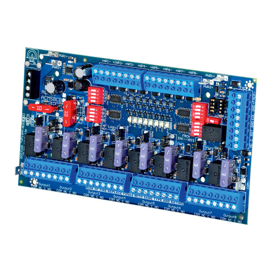
- Page 1 ACMS8 Series Sub-Assembly Access Power Controllers Installation Guide Models Include: ACMS8 - Eight (8) Fuse Protected Outputs ACMS8CB - Eight (8) PTC Protected Outputs More than just power. Rev. 102617...
-
Page 2: Specifications
Outputs are activated by an open collector sink, normally open (NO), normally closed (NC) dry trigger input, or wet output from an Access Control System, Card Reader, Keypad, Push Button, PIR, etc. ACMS8(CB) will route power to a variety of access control hardware devices including Mag Locks, Electric Strikes, Magnetic Door Holders, etc. -
Page 3: Installation Instructions
When form “C” outputs are desired, the corresponding jumper (1-8) must be placed in the OFF position (Fig. 1, pg. 3). Alternatively, the corresponding output fuse (1-8) can be removed (ACMS8 only). Connect negative (–) of the power supply directly to the locking device. -
Page 4: Led Diagnostics
Eight (8) selectable 5VDC-24VDC independently controlled outputs [Fail-Safe (NC) or Output 8 Fail-Secure (NO)] and eight (8) independently controlled Form “C” Relay outputs. NO, C, NC, COM Fuses are rated 2.5A each (ACMS8). PTCs are rated 2A each (ACMS8CB). - 4 - ACMS8/CB Sub-Assembly... - Page 5 Use 18 AWG or larger UL Listed wire equipped with 1/4” UL Recognized quick connect terminals rated for proper voltage/current for all jumper connections. 1. Connect first ACMS8(CB) board’s spade lug marked [PWR1 +] to the second ACMS8(CB) board’s spade lug marked [PWR1 +].
- Page 6 VR6 voltage regulator converts a 24VDC input into a regulated 5VDC or 12VDC output. It is specifically designed to work with ACMS8(CB) by allowing to mount the Access Power Controller directly on top of VR6 to save enclosure space and simplify connections. Refer to VR6 Installation Guide Rev. 050517.
-
Page 7: Typical Application Diagram
Output 6 Output 7 Output 8 NC COM NO NC COM NC COM NO NC COM NC COM NO NC COM NC COM NO NC COM Mag. Lock Electric Strike Electromagnetic Door Holders ACMS8 ACMS8CB ACMS8/CB Sub-Assembly - 7 -... -
Page 8: Hookup Diagrams
EOL JMP EOL JMP N.O. Jumper Switch FACP FACP Fig. 9 - Daisy chaining one or more ACMS8 units. EOL Jumper [EOL JMP] should be installed in the EOL position. Latching Individual Reset. FACP FACP EOL JMP EOL JMP N.O. - Page 9 (Non-Latching). (Latching). FACP FACP Jumper Jumper FACP FACP Normally Open trigger input Normally Open trigger input Fig. 14 - Fig. 15 - (Non-Latching). (Latching). FACP FACP N.O. N.O. Switch Switch N.O. Jumper Switch FACP FACP ACMS8/CB Sub-Assembly - 9 -...
- Page 10 Notes: - 10 - ACMS8/CB Sub-Assembly...
- Page 11 Notes: ACMS8/CB Sub-Assembly - 11 -...
- Page 12 Notes: Altronix is not responsible for any typographical errors. 140 58th Street, Brooklyn, New York 11220 USA | phone: 718-567-8181 | fax: 718-567-9056 website: www.altronix.com | e-mail: info@altronix.com | Lifetime Warranty | Made in U.S.A. MEMBER IIACMS8/ACMS8CB C20R - 12 -...
Need help?
Do you have a question about the ACMS8 and is the answer not in the manual?
Questions and answers