
Summary of Contents for Smartek UCC
- Page 1 User Manual twentynine Camera Family www.SMARTEK.vision SMARTEK d.o.o. 2017, information is subject to change without prior notice, Version 1.0.2 from 2017-07-03...
- Page 2 Users using or selling these products for use in such applications do so at their own risk and agree to fully indemnify SMARTEK d.o.o. for any damages resulting from any improper use or sale. www.SMARTEK.vision SMARTEK d.o.o. 2017, information is subject to change without prior notice, Version 1.0.2 from 2017-07-03...
- Page 3 SMARTEK d.o.o except to identify the products or services of the company. Warranty SMARTEK d.o.o. has made reasonable efforts to ensure that the information provided in this document is accurate at the time of inclusion. However there may be unintentional and occasional errors for which we apologize.
-
Page 4: Table Of Contents
3.2 USB3.0 Interface (UCC) ........ - Page 5 6.3.2 Installation USB3 Vision Device Driver ......SMARTEK Vision | User Manual - twentynine | Doc. v1.0.2...
- Page 6 8.3 Color Image Processing Pipeline ........146 9 Revision History 10 Contact Information SMARTEK Vision | User Manual - twentynine | Doc. v1.0.2...
-
Page 7: Platform Specification
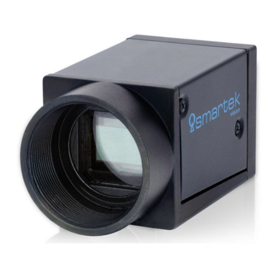
User Manual - twentynine 1 Platform Specification The SMARTEK Vision twentynine camera family offers an affordable and easy to use set of digital cameras designed to meet demanding high quality machine vision applications, conforming to the industrial GigE Vision and USB3 Vision standard. The compact housing fits almost every space critical application. -
Page 8: Twentynine Standard
1 output channel, opto-isolated Digital output USB3.0 (Micro-B) 1GBase-T / 100Base-T (RJ45) Data/Control Interface CE, RoHS II, GenICam Conformity1 USB3 Vision GigE Vision, PoE (IEEE802.3af) Conformity2 Table 1: Mechanical and electrical specifications SMARTEK Vision | User Manual - twentynine | Doc. v1.0.2... -
Page 9: Technical Drawings
6,80 optical center 2,12 53,80 2x M 2,0 3x M 3,0 0,47 0,79 Figure 1: Technical measures of the GCC camera housing (all dimensions are in mm [inch]) SMARTEK Vision | User Manual - twentynine | Doc. v1.0.2... - Page 10 6,80 image sensor optical center 2,12 53,80 2x M 2,0 3x M 3,0 0,47 0,79 Figure 2: Technical measures of the UCC camera housing (all dimensions are in mm [inch]) SMARTEK Vision | User Manual - twentynine | Doc. v1.0.2...
-
Page 11: Supported Industry Standards
Features of the USB3 Vision standard: Very-high data transfer rates - up to 350 MB/s Plug-and-play interface for easy use Uses GenICam generic programming interface Based on established standard USB3.0 SMARTEK Vision | User Manual - twentynine | Doc. v1.0.2... -
Page 12: Genicam
The GenApi module of the GenICam standard defines how to write a camera description file that describes a specific camera’s mapping. For detailed information about this convention visit www.emva.org. SMARTEK Vision | User Manual - twentynine | Doc. v1.0.2... -
Page 13: C-Mount
Cognex Vision Pro Native (GigEVision interface) Matrox Imaging Library Native (GigEVision interface) MVTec Halcon National Instruments National Instruments IMAQdx (Plugin) LabView Plugin provided by SMARTEK Vision Scorpion Vision Table 2: Third-Party Software SMARTEK Vision | User Manual - twentynine | Doc. v1.0.2... -
Page 14: Ir-Cut Filter Specification
IR-cut filter installed by default. Figure 3 below shows the transmission curve of the filter used in the twentynine camera family. 1000 Wavelength (nm) Figure 3: IR-cut filter specification SMARTEK Vision | User Manual - twentynine | Doc. v1.0.2... -
Page 15: Precautions
Operate this cameras only with the type of power source that meets the specifications indicated on the camera and within the documentation. Operating the camera outside of the specifications can cause to permanent damage. SMARTEK Vision | User Manual - twentynine | Doc. v1.0.2... -
Page 16: Emi And Esd Consideration
Decrease the risk of electrostatic discharge by taking the following measures: Use conductive materials at the point of installation. Use suitable clothing (cotton) and shoes. Control the humidity in your environment. Low humidity can cause ESD problems. SMARTEK Vision | User Manual - twentynine | Doc. v1.0.2... -
Page 17: Temperature And Heat Dissipation
The thermal noise generated in silicon based sensors raises exponentially with the temperature, hereby the useful signal falls rapidly. As every application and environment has its own characteristics, SMARTEK Vision can only suggest general strategies to keep the camera’s temperature low: Mount housed cameras with at least one complete side of the housing to a massive heat conductive material (e.g. -
Page 18: Ingress Protection Class
The camera housing fulfills the Ingress Protection Class of IP40. It is protected against solid objects with a diameter larger than 1 mm (tools, wires, and small wires) and has no protection against liquids. SMARTEK Vision | User Manual - twentynine | Doc. v1.0.2... -
Page 19: Declarations Of Conformity
Damir Dolar Smartek d.o.o. SMARTEK Vision | User Manual - twentynine | Doc. v1.0.2... -
Page 20: Rohs
UCC1932M, UCC2061C, UCC2061M, UCC2062C, UCC2062M, UCC2461C, UCC2461M, UCC2462C, UCC2462M. This equipment is in compliance with the essential requirements and other relevant provisions of the RoHS II Directive 2011/65/EU. Damir Dolar Smartek d.o.o. SMARTEK Vision | User Manual - twentynine | Doc. v1.0.2... -
Page 21: Model Overview
Exposure control Freely programmable via GigE/USB3 Vision interface Power consumption (AUX @12V) 3.2W — Power consumption (PoE / USB) 3.8W 2.9W Table 4: Model specific specification of GCC1931 / UCC1931 SMARTEK Vision | User Manual - twentynine | Doc. v1.0.2... - Page 22 1000 Wavelength (nm) Figure 5: Relative response of GCC1931 / UCC1931 Monochrome (from sensor datasheet) 1000 Wavelength (nm) Figure 6: Relative response of GCC1931 / UCC1931 Color (from sensor datasheet) SMARTEK Vision | User Manual - twentynine | Doc. v1.0.2...
-
Page 23: Gcc1932 / Ucc1932
Exposure control Freely programmable via GigE/USB3 Vision interface Power consumption (AUX @12V) 3.1W — Power consumption (PoE / USB) 3.7W 2.3W Table 5: Model specific specification of GCC1932 / UCC1932 SMARTEK Vision | User Manual - twentynine | Doc. v1.0.2... - Page 24 1000 Wavelength (nm) Figure 7: Relative response of GCC1932 / UCC1932 Monochrome (from sensor datasheet) 1000 Wavelength (nm) Figure 8: Relative response of GCC1932 / UCC1932 Color (from sensor datasheet) SMARTEK Vision | User Manual - twentynine | Doc. v1.0.2...
-
Page 25: Gcc2061 / Ucc2061
Exposure control Freely programmable via GigE/USB3 Vision interface Power consumption (AUX @12V) 3.4W — Power consumption (PoE / USB) 4.1W 3.1W Table 6: Model specific specification of GCC2061 / UCC2061 SMARTEK Vision | User Manual - twentynine | Doc. v1.0.2... - Page 26 User Manual - twentynine Relative Response Figure 9: Relative response of GCC2061 / UCC2061 Monochrome (from sensor datasheet) Figure 10: Relative response of GCC2061 / UCC2061 Color (from sensor datasheet) SMARTEK Vision | User Manual - twentynine | Doc. v1.0.2...
-
Page 27: Gcc2062 / Ucc2062
Exposure control Freely programmable via GigE/USB3 Vision interface Power consumption (AUX @12V) 3.4W — Power consumption (PoE / USB) 4.0W 2.8W Table 7: Model specific specification of GCC2062 / UCC2062 SMARTEK Vision | User Manual - twentynine | Doc. v1.0.2... - Page 28 User Manual - twentynine Relative Response Figure 11: Relative response of GCC2062 / UCC2062 Monochrome (from sensor datasheet) Figure 12: Relative response of GCC2062 / UCC2062 Color (from sensor datasheet) SMARTEK Vision | User Manual - twentynine | Doc. v1.0.2...
-
Page 29: Gcc2461 / Ucc2461
Exposure control Freely programmable via GigE/USB3 Vision interface Power consumption (AUX @12V) 3.5W — Power consumption (PoE / USB) 4.2W 3.2W Table 8: Model specific specification of GCC2461 / UCC2461 SMARTEK Vision | User Manual - twentynine | Doc. v1.0.2... - Page 30 User Manual - twentynine Relative Response Figure 13: Relative response of GCC2461 / UCC2461 Monochrome (from sensor datasheet) Figure 14: Relative response of GCC2461 / UCC2461 Color (from sensor datasheet) SMARTEK Vision | User Manual - twentynine | Doc. v1.0.2...
-
Page 31: Gcc2462 / Ucc2462
Exposure control Freely programmable via GigE/USB3 Vision interface Power consumption (AUX @12V) 3.5W — Power consumption (PoE / USB) 4.0W 2.8W Table 9: Model specific specification of GCC2462 / UCC2462 SMARTEK Vision | User Manual - twentynine | Doc. v1.0.2... - Page 32 User Manual - twentynine Relative Response Figure 15: Relative response of GCC2462 / UCC2462 Monochrome (from sensor datasheet) Figure 16: Relative response of GCC2462 / UCC2462 Color (from sensor datasheet) SMARTEK Vision | User Manual - twentynine | Doc. v1.0.2...
-
Page 33: Physical Interfaces
OPTO-ISOLATED IN (1x) OPTO-ISOLATED OUT (1x) Figure 17: GCC connecting scheme USB3 cable USB3 Power and I/O OPTO-ISOLATED IN (1x) receptacle OPTO-ISOLATED OUT (1x) Figure 18: UCC connecting scheme SMARTEK Vision | User Manual - twentynine | Doc. v1.0.2... -
Page 34: Gigabit Ethernet Interface (Gcc)
OR 2 3 GRN/WHT GRN/WHT 3 4 BLU BLU 4 5 BLU/WHT BLU/WHT 5 6 GRN GRN 6 7 BRN/WHT BRN/WHT 7 8 BRN BRN 8 Figure 19: Straight-through cable scheme SMARTEK Vision | User Manual - twentynine | Doc. v1.0.2... -
Page 35: Usb3.0 Interface (Ucc)
Bad cabling, connectors and/or shielding can lead to decreased performance (e.g. framerates) up to connection interrupts. It is thus highly recommended to purchase the Note right industrial cabling from our local SMARTEK Vision distribution partner to prevent issues in performance. SMARTEK Vision | User Manual - twentynine | Doc. v1.0.2... -
Page 36: Power And I/O Interface
GND for direct coupled I/O (optional) Table 13: 6-pin circular Hirose receptacle - Pin assignment The 6-pin connector on the camera is a Hirose receptacle and can be used with a Note HR10-7P-6S or equivalent. SMARTEK Vision | User Manual - twentynine | Doc. v1.0.2... -
Page 37: Cabling Requirements
Note is recommended to use shielded twisted pair wires to ensure that signals are correctly transmitted. An incorrect pin assignment or connector can lead to permanent damages to the camera. SMARTEK Vision | User Manual - twentynine | Doc. v1.0.2... -
Page 38: Input Lines (Electrical Specification)
TLP2366 External GND Figure 22: Trigger input scheme Exceeding the limits shown in Table 14 or reneging the wiring polarity shown in Caution Figure 22 can seriously damage the device! SMARTEK Vision | User Manual - twentynine | Doc. v1.0.2... -
Page 39: Output Lines (Electrical Specification)
GND for opto-isolated I/O External GND Figure 23: Digital output scheme Exceeding the limits shown in Table 15 or reneging the wiring polarity shown in Caution Figure 23 can seriously damage the device! SMARTEK Vision | User Manual - twentynine | Doc. v1.0.2... -
Page 40: Status Led
1 pulse - no user firmware present 2 pulses - user firmware watchdog timeout 3 pulses - user firmware data CRC error 4 pulses - error configuring FPGA (NSTATUS asserted) Table 16: Status LED SMARTEK Vision | User Manual - twentynine | Doc. v1.0.2... -
Page 41: General Camera Architecture
The image data is segmented into GigE Vision / USB3 Vision packets and transmitted to the host computer. The Transport Layer Controller also handles transmission and reception of control data which are processed by the FPGA. SMARTEK Vision | User Manual - twentynine | Doc. v1.0.2... -
Page 42: Cmos Sensor Readout
FPGA. The electronics in the camera’s frontend are mainly dedicated to provide clean and separated supply powers for the sensor and its periphery, and route the sensor control bus (I C / SPI). SMARTEK Vision | User Manual - twentynine | Doc. v1.0.2... -
Page 43: Color Imaging With Bayer Pattern
At a green color filter position, green light is fully transmitted, red and blue light are reflected or absorbed by the filter And at a blue color filter position, blue light is fully transmitted, red and green light are reflected or absorbed by the filter SMARTEK Vision | User Manual - twentynine | Doc. v1.0.2... - Page 44 filter array interpolation, demosaicing or debayering. For more detailed description of the debayering methods, please refer to chapter 8.2.6 - Color Filter Array Interpolation (Demosaicing / Debayering) in this user manual. SMARTEK Vision | User Manual - twentynine | Doc. v1.0.2...
-
Page 45: Shutter Types And Frame Readout
CMOS sensors tends to be smaller compared to electronic rolling shutter sensors. This is usually compensated by a micro lens above each pixel, which focuses the incoming light to the light sensitive surface. SMARTEK Vision | User Manual - twentynine | Doc. v1.0.2... -
Page 46: Electronic Rolling Shutter (Ers) Readout
Figure 30 shows this illumination window as t , staring at t Illumination IlluminationDelay SMARTEK Vision | User Manual - twentynine | Doc. v1.0.2... - Page 47 The timing of illumination or mechanical shutter can be calculated with the formulas below. Delay of illumination / shutter open: × (ImageHeight − 1) IlluminationDelay ReadRow On time of illumination / shutter open: − (t × (ImageHeight − 1)) Illumination Exposure ReadRow SMARTEK Vision | User Manual - twentynine | Doc. v1.0.2...
-
Page 48: Global Reset Release (Grr) Readout
The illumination of the sensor can in this case already be started with the sensor exposure, but must end with the exposure of Line 1, what corresponds to the overall exposure time configured in the camera. SMARTEK Vision | User Manual - twentynine | Doc. v1.0.2... -
Page 49: Camera Features
Line Input Delay (Trigger) Configuration Storing (User Sets) Acquisition / Exposure / Frame Active (Output) Acquisition / Frame Trigger Wait (Output) User Defined Outputs Table 17: Camera feature list (1/2) SMARTEK Vision | User Manual - twentynine | Doc. v1.0.2... - Page 50 Frame Transfer Delay Time Stamps Pixel Data Formats Mono8 Mono10Packed Mono12Packed Bayer8 Bayer10Packed Bayer12Packed Mono models only Horizontal (mono models only) Color models only Table 18: Camera feature list (2/2) SMARTEK Vision | User Manual - twentynine | Doc. v1.0.2...
-
Page 51: Brightness And Sensor Signal Control
Figure 32: Different exposure time settings The exposure time for SMARTEK Vision digital cameras is configurable by the GenICam Float property ExposureTime and is expressed in microseconds ( s). Each camera has a predefined range of values, µ... - Page 52 The automatic modification of the camera’s exposure time within user applications can be realized by using the ImageProcAPI provided by the CameraSuite SDK. For detailed description of the automatic exposure feature please refer to chapter 8.2.3 - Auto Exposure and Auto Gain . SMARTEK Vision | User Manual - twentynine | Doc. v1.0.2...
-
Page 53: Analog Gain And Black Level
Figure 33: Typical signal chain in a CCD/CMOS image sensor In SMARTEK Vision digital cameras gain values are expressed in decibels (dB), the analog gain defines the ratio between the output and input voltage value in a base 10 logarithmic scale: Gain = 20 ×... - Page 54 User Manual - twentynine Figure 34: Captures under different gain settings The analog gain on SMARTEK Vision digital cameras is configurable by the GenICam Float property Gain in combination with the Enumeration property GainSelector . The following tables show important C++ API functions in context of the gain. As several cameras provide multiple gain registers giving access to the gain of individual color channels or various taps, the type of gain needs to be chosen first by the GainSelector property, shown in Table 20.
-
Page 55: Black Level
(CCD) or the sensor (CMOS) and is by default set to 0. It can be used to reduce the amount of Dark Current subtracted from the signal by adding a user defined offset to the overall signal. SMARTEK Vision | User Manual - twentynine | Doc. v1.0.2... -
Page 56: Automatic Exposure And Gain Control
As described in previous chapters the image brightness can be adjusted by changing exposure time and gain values. The SMARTEK Vision twentynine camera series provides on-camera automatic control of exposure time and gain, thus automatically adjusting the values within defined limits, until the specified target image brightness is reached. -
Page 57: Digital Shift
Further it makes the lower bits of the ADC accessible to detect very low signals while transferring 8 bit pixels, without a further amplification of the signal. SMARTEK Vision | User Manual - twentynine | Doc. v1.0.2... -
Page 58: Gamma Adjustment
0.1 to 4.0 by a step of 0.1. By default the gamma value is equal to 1.0 . Figure 36: Modify gamma value in CameraSuiteClient SMARTEK Vision | User Manual - twentynine | Doc. v1.0.2... -
Page 59: Luminance Look-Up-Table
In order to modify individual LUT value it is neccessary that the Visibilty option is set to Guru . Modifying each value in the LUT means first select the required index and second set the desired value (see Figure 39). SMARTEK Vision | User Manual - twentynine | Doc. v1.0.2... - Page 60 User Manual - twentynine Figure 38: Enable LUT feature on Camera in CameraSuiteClient Figure 39: Modify individual LUT value in CameraSuiteClient SMARTEK Vision | User Manual - twentynine | Doc. v1.0.2...
-
Page 61: Region Of Interest (Roi)
ROI are allowed ( OffsetX, OffsetY ). Changes to parameters that define the ROI size ( Width, Height ) are not allowed. Changes to parameters while the image acquisition process is active is also called "on-the-fly" changes. SMARTEK Vision | User Manual - twentynine | Doc. v1.0.2... -
Page 62: Multiple Regions Of Interest
The width of the resulting image is equal to the sum of widths of all vertical stripes: ImageWidth = VStripe.width The height of the resulting image is equal to the sum of widths of all horizontal stripes: ImageHeight = HStripe.width SMARTEK Vision | User Manual - twentynine | Doc. v1.0.2... - Page 63 ROI ( OffsetX, OffsetY ) as they might influence the horizontal and vertical stripes forming the resulting image. "On-the-fly" change of the parameter RegionMode is also not allowed as it results in enabling or disabling of a Region of Interest . SMARTEK Vision | User Manual - twentynine | Doc. v1.0.2...
-
Page 64: Region Of Interest Centering
1 2 3 4 5 6 7 8 9 10 11 12 13 14 15 16 17 18 19 20 Automatically calculated Offset Y Transmitted Pixels Width Automatically calculated Offset X Figure 42: Center X & Y SMARTEK Vision | User Manual - twentynine | Doc. v1.0.2... -
Page 65: Acquisition Control
User Manual - twentynine 5.4 Acquisition Control The following section is about controlling the image acquisition of SMARTEK Vision digital cameras. It contains a detailed description about the different acquisition modes, how to control external triggering and how the image acquisition rate can be limited. Table 29 gives a brief overview about all features that are available to control the image acquisition in the cameras. -
Page 66: Acquisition Mode
The Trigger Features chapter describes features related to synchronizing the camera with an external device or software application. 5.4.2.1 Trigger Selector The TriggerSelector property provides access to the properties of different triggers supported by the camera, as shown in Table 31. SMARTEK Vision | User Manual - twentynine | Doc. v1.0.2... -
Page 67: Trigger Mode
Specifies that the trigger is considered valid on the rising edge of the source signal RisingEdge Specifies that the trigger is considered valid on the falling edge of the source signal FallingEdge Table 34: Trigger Activation modes SMARTEK Vision | User Manual - twentynine | Doc. v1.0.2... -
Page 68: Trigger Delay
AcquisitionFrameRate parameter. In order to enable the Free Run mode, all triggers must be disabled ( TriggerMode set to Off ) and Acquisition Mode must be set to Continuous . SMARTEK Vision | User Manual - twentynine | Doc. v1.0.2... -
Page 69: Digital Input / Output Control
filtered by the LineDebouncer and raises the internal trigger signal (if valid). The user defined TriggerDelay increased by the fixed trigger latency caused by internal circuitry defines the start of the triggered event. SMARTEK Vision | User Manual - twentynine | Doc. v1.0.2... - Page 70 User Manual - twentynine Figure 45: Partial process of image acquisition SMARTEK Vision | User Manual - twentynine | Doc. v1.0.2...
-
Page 71: Line Debouncer
filter unwanted glitches that could trigger the camera, but small enough to keep the delay as small as possible. Figure 46: Line debouncer function SMARTEK Vision | User Manual - twentynine | Doc. v1.0.2... -
Page 72: Output Lines
The value of this property can be accessed after selecting the appropriate value by the UserOutputSelector , according to Table 37. Description Value Type Enumeration Select between UserOutput1 and UserOutput2 UserOutputSelector Value of the selected UserOutput Boolean UserOutputValue Table 37: User Outputs SMARTEK Vision | User Manual - twentynine | Doc. v1.0.2... -
Page 73: Gige Vision Specific Features
User Manual - twentynine 5.6 GigE Vision Specific Features The network interface of SMARTEK Vision digital cameras is designed to be fully compatible with the GigE Vision standard. The following section describes features of the data interface of the twentynine series as well as the SMARTEK Vision GigEVision Filter Driver. - Page 74 Should the amount of packet resends rise to Note a unnatural height, check the correctness of the physical network setup (cabling, switches) and the network optimization settings located in chapter 7.1.3 - Network Interface Optimization . SMARTEK Vision | User Manual - twentynine | Doc. v1.0.2...
- Page 75 PacketResendResponseTimeout has expired, packet 1007 is now considered as lost. If a group of packets is missing (for example 1000, 1001, 1002 and 1003 ), only one resend request will be sent covering all connected packets. SMARTEK Vision | User Manual - twentynine | Doc. v1.0.2...
- Page 76 Additionally to the description in Example 2, the workflow of the Packet Resent mechanism would be enhanced by the following definitions: 1. Interval defined by MaxMissingPacketWaiting parameter. 2. As the MaxMissingPacketWaiting time has expired, missing packet is considered as lost. SMARTEK Vision | User Manual - twentynine | Doc. v1.0.2...
-
Page 77: Inter-Packet Delay
Delay Packet 2 Camera 1 Each camera has dedicated time slot Packet 1 Packet 1 Camera 2 Delay Packet 2 Delay Figure 50: Packet flow while using inter packet delay SMARTEK Vision | User Manual - twentynine | Doc. v1.0.2... -
Page 78: Setting Inter Packet Delay
Camera 2 Delay Packet 2 Delay Packet 1 Packet 1 Packet 1 Camera 3 Delay Packet 2 Delay Figure 51: Packet flow example with three cameras and inter packet delay SMARTEK Vision | User Manual - twentynine | Doc. v1.0.2... -
Page 79: Frame Transfer Delay
Camera 1 is transferred and Camera 3 will start sending data after frame from Camera 2 is transferred. Next trigger is not allowed until all cameras finish sending data. SMARTEK Vision | User Manual - twentynine | Doc. v1.0.2... -
Page 80: Setting Frame Transfer Delay
Formula to calculate number of ticks for given time value is shown below: GevSCFTD = FrameTransferDelay × GevTimestampTickFrequency GevTimestampTickFrequency - indicates the number of timestamp ticks during 1 second SMARTEK Vision | User Manual - twentynine | Doc. v1.0.2... -
Page 81: Digital Image And Pixel Formats
It is identical for all cameras. 5.7.1 Image Layout Figure 53 shows the image layout valid for all SMARTEK Vision digital cameras. An image transmitted out of a camera is considered to be a two-dimensional array of pixels. The pixels are stored in subsequent addresses in the memory of the capture device, usually a PC. -
Page 82: Mono8
Figure 54: Image layout with pixel format Mono8 5.7.3 Mono10Packed In an image with the pixel format Mono10Packed each two pixel values are represented by three bytes or 24 bits. The Mono10Packed pixel format in SMARTEK Vision digital cameras is specified as shown below: PixelFormat Mono10Packed... -
Page 83: Mono12Packed
User Manual - twentynine 5.7.4 Mono12Packed In an image with the pixel format Mono12Packed each two pixel values P are represented by three bytes or 24 bits. The Mono12Packed pixel format in SMARTEK Vision digital cameras is specified as shown below: PixelFormat Mono12Packed... -
Page 84: Bayergr8 / Bayerrg8 / Bayergb8 / Bayerbg8
For detailed description about color imaging and the Bayer filter, please refer to chapter 4.2 - Color Imaging with Bayer Pattern . The Bayer8 pixel formats in SMARTEK Vision digital cameras are specified like shown below: PixelFormat... -
Page 85: Bayergr16, Bayerrg16, Bayergb16, Bayerbg16
"RG", "GB" or "BG" notation describes the Bayer pattern of the image sensor used in the camera. For detailed description about the Bayer filter, please refer to chapter 4.2 - Color Imaging with Bayer Pattern. The Bayer16 pixel format in SMARTEK Vision digital cameras is specified like shown below: PixelFormat... -
Page 86: Camerasuite Sdk
6.1 Supported Operating Systems The SMARTEK Vision CameraSuite SDK has been created to support Microsoft Windows 7, 8, 8.1 and 10 operating systems. The installation packages for the supported operating systems are available in 32-bit(x86) and 64-bit(x64) system architecture. Table 46 contains a list of the supported operating systems and the appropriate installation package. -
Page 87: Installation Of The Camerasuite Sdk
User Manual - twentynine 6.2 Installation of the CameraSuite SDK The installation packages for the latest CameraSuite SDK can be downloaded from the SMARTEK Vision webpage: http://www.SMARTEK.vision/media-center After downloading and executing the installation package, the user can choose which part of the SDK to install, shown in Figure 60. -
Page 88: Manual Driver Installation
..\drivers\FilterDriver\GigEVDrvInstall.exe There are several flags that control the installer execution: /install - Installs the Smartek GigE Vision Filter Driver. it can be used with optional flags like /v or /hide. /uninstall - Uninstalls the Smartek GigE Vision Filter Driver. it can be used with optional flags like /v or /hide. -
Page 89: Unattended Sdk Installation (Microsoft Windows)
GigE Vision or USB3 Vision complaint cameras. After the installation of the CameraSuite SDK the CameraSuiteClient can be started by the appropriate shortcut in the Microsoft Windows Start menu (All Programs ⇒ SMARTEK Vision). The binaries can be found within the installation directory, usually located at:... -
Page 90: Graphical User Interface (Gui)
Info Bar - Displays information like image size, frame rate, data transfer rate, cursor position and pixel value at cursor position. Image Display Window - Main window for displaying a single image or video stream. SMARTEK Vision | User Manual - twentynine | Doc. v1.0.2... - Page 91 Figure 62. The Floating Display feature allows the user to arrange different image displaying Note windows for each camera’s video stream on the screen. SMARTEK Vision | User Manual - twentynine | Doc. v1.0.2...
-
Page 92: Acquire Images From Camera(S)
3. The device uses the GigE Vision filter driver from another manufacturer For USB3 Vision compliant devices: 1. No USB3 Vision device driver is installed correctly on the device 2. The device uses the USB3 Vision device driver from another manufacturer SMARTEK Vision | User Manual - twentynine | Doc. v1.0.2... - Page 93 Note camera, described in chapter 3.1 - Ethernet Interface . Make sure everything is plugged properly and that the firewall settings are not blocking the connection to camera or CameraSuiteClient. SMARTEK Vision | User Manual - twentynine | Doc. v1.0.2...
-
Page 94: Device Ip Setup
After setting a valid IP address configuration to the camera, the warning symbol next to the camera model name will change like shown in Figure 66, the Connect Device icon can now be used to connect to the selected camera. SMARTEK Vision | User Manual - twentynine | Doc. v1.0.2... - Page 95 User Manual - twentynine Figure 66: Connect Device icon SMARTEK Vision | User Manual - twentynine | Doc. v1.0.2...
-
Page 96: Device Properties
Figure 68. To receive a continuous image stream from the camera, without having any external trigger signals applied, it must be ensured that the AcquisitionMode is set to Continuous and the TriggerMode is set to Off . SMARTEK Vision | User Manual - twentynine | Doc. v1.0.2... - Page 97 A running acquisition can be quit by pressing the Stop -button. Multiple acquisitions can be started in parallel by choosing further cameras, the output of the currently selected device is shown in the Image Display window. SMARTEK Vision | User Manual - twentynine | Doc. v1.0.2...
-
Page 98: Multiple Devices, Multiple Views
The maximum number of devices depends on the memory and performance of the Note host PC, as each of the devices will cause an amount of load to the system. SMARTEK Vision | User Manual - twentynine | Doc. v1.0.2... -
Page 99: Image Processing
GIMP based color manipulation via hue, lightness and Only available for color GIMP saturation cameras Look Up Table generation, application and storing/loading Other Image sharpening, Image Flip/Rotate Table 47: CameraSuiteClient - Image processing functions SMARTEK Vision | User Manual - twentynine | Doc. v1.0.2... -
Page 100: Api Settings Dialog
256MB, Windows 7 to 75% of physical RAM), the number of images in the image buffer must be calculated correctly. Figure 71: API Settings Additionally the Device tab of the API Settings dialog provides access to the packet statistics on device side. SMARTEK Vision | User Manual - twentynine | Doc. v1.0.2... -
Page 101: Chunk Data Control
When chunk mode is enabled and acquisition is started, enabled chunks will be displayed in new tab that appeared under Image Processing Properties. Figure 73 shows chunk data values tab. Figure 73: Chunk Data Values SMARTEK Vision | User Manual - twentynine | Doc. v1.0.2... -
Page 102: Log Dialog
CounterValue: Set / read counter value 6.5.5 Log Dialog The Log dialog contains logging information from SDK and cameras, shown in Figure 76. Figure 76: Log dialog with API logging SMARTEK Vision | User Manual - twentynine | Doc. v1.0.2... -
Page 103: Firmware Update
Figure 77: Firmware update dialog after the update is successfully executed In case of any errors during the update process, please repeat the firmware upload. Do not force a restart of the camera before the process has been finished successfully! SMARTEK Vision | User Manual - twentynine | Doc. v1.0.2... -
Page 104: Gige Vision / Usb3 Vision Specific Notes
Pro/1000 CT Desktop (single port) or PT Server Adapter (multiport). Jumbo packets / frames need to be supported by the NIC as well as the whole network Note chain, including all network switches passed on the route. SMARTEK Vision | User Manual - twentynine | Doc. v1.0.2... -
Page 105: Lan Ip Configuration
Figure 78, usually provided by routers or dedicated servers. A fixed IP address and Subnet mask can be entered like shown in Figure 78 right, after choosing Use the following IP address . Figure 78: Internet Protocol Version 4 (TCP/IPv4) properties SMARTEK Vision | User Manual - twentynine | Doc. v1.0.2... -
Page 106: Network Interface Optimization
4. The settings of the driver can be accessed by choosing the Advanced tab of the opened window. As shown in Figure 80, raise the value of the Jumbo Packet property to its maximum value. SMARTEK Vision | User Manual - twentynine | Doc. v1.0.2... -
Page 107: Jumbo Frames - Gigabit Ethernet Switches
(in most cases with a web based GUI), have it in many cases disabled as it is configurable for each port separately. For validation please refer to the documentation of your individual device. SMARTEK Vision | User Manual - twentynine | Doc. v1.0.2... -
Page 108: Raising Receive Buffers
4. The settings of the driver can be accessed by choosing the Advanced tab of the opened window. As shown in Figure 81, raise the value of the Receive Buffers property to its maximum value. Figure 81: Network interface card - advanced driver settings - Receive Buffers SMARTEK Vision | User Manual - twentynine | Doc. v1.0.2... -
Page 109: Disable The Interrupt Moderation Rate
Figure 82, set the value of the Interrupt Moderation Rate property to Off or Disabled . Figure 82: Network interface card - advanced driver settings - Interrupt Moderation Rate SMARTEK Vision | User Manual - twentynine | Doc. v1.0.2... -
Page 110: Disable The Flow Control
4. The settings of the driver can be accessed by choosing the Advanced tab of the opened window. As shown in Figure 83 , set the value of the Interrupt Moderation Rate property to Disabled . Figure 83: Network interface card - advanced driver settings - Flow Control SMARTEK Vision | User Manual - twentynine | Doc. v1.0.2... -
Page 111: Usb3 Vision
Bad cabling, connectors and/or shielding can lead to decreased performance (e.g. framerates) up to connection interrupts. It is thus highly recommended to purchase the Note right industrial cabling from our local SMARTEK Vision distribution partner to prevent issue in performance. SMARTEK Vision | User Manual - twentynine | Doc. v1.0.2... -
Page 112: Image Processing In Camerasuite Sdk
For a more detailed description on the parameters of each algorithm or on how to apply them, please refer to the CameraSuite API help located at the doc folder of the CameraSuite SDK installation directory. SMARTEK Vision | User Manual - twentynine | Doc. v1.0.2... -
Page 113: Image Statistics
Number of pixels with value 80 = 5774 … … 5774 4535 … … 1191 Histogram table Pixel value = 80 Figure 84: Source image with histogram graph and table SMARTEK Vision | User Manual - twentynine | Doc. v1.0.2... - Page 114 Histogram of Histogram of Histogram of Overexposed Image red channel green channel blue channel Histogram of Histogram of Histogram of red channel green channel blue channel Underexposed Image SMARTEK Vision | User Manual - twentynine | Doc. v1.0.2...
- Page 115 API Help located in the doc folder of the CameraSuite SDK installation directory. Supported bit depth Supported image input 8 bit per channel 16 bit per channel Monochrome Raw Bayer Color RGB Table 50: Histogram - supported bit depth and image types SMARTEK Vision | User Manual - twentynine | Doc. v1.0.2...
- Page 116 Figure 86: Histogram feature in CameraSuiteClient Skip Images (default 5): Number of frames to skip before a new histogram is calculated and the GUI is updated. Enable / Disable: Active / deactivate histogram calculation. SMARTEK Vision | User Manual - twentynine | Doc. v1.0.2...
-
Page 117: Average Luminance Calculation
Supported bit depth Supported image input 8 bit per channel 16 bit per channel Monochrome Raw Bayer Color RGB Table 51: Average luminance calculation - supported bit depth and image types SMARTEK Vision | User Manual - twentynine | Doc. v1.0.2... - Page 118 Color / Mono , shown in Figure 87. If not visible, it can be enabled by the menu bar entry Control ⇒ Image Processing Properties . Figure 87: Average value calculation in CameraSuiteClient for White Balancing algorithm SMARTEK Vision | User Manual - twentynine | Doc. v1.0.2...
-
Page 119: Image Processing Algorithms
The look-up table is a linear function (f(x) = x) and its graph is a 45 ◦ straight line, shown in Figure 89. Because of the one-to-one value mapping the output image is identical to the input image. SMARTEK Vision | User Manual - twentynine | Doc. v1.0.2... - Page 120 Figure 90, it is visible that a non-linear transformation is applied to the input pixel values. Figure 90: Gamma correction using look-up table SMARTEK Vision | User Manual - twentynine | Doc. v1.0.2...
- Page 121 … … Input Image 105 120 135 150 165 180 195 210 225 240 255 index … … Output Image Figure 92: Enhancing contrast of an image using look-up table SMARTEK Vision | User Manual - twentynine | Doc. v1.0.2...
- Page 122 Supported bit depth Supported image input 8 bit per channel 16 bit per channel Monochrome Raw Bayer Color RGB Table 52: Look-up table - supported bit depth and image types SMARTEK Vision | User Manual - twentynine | Doc. v1.0.2...
- Page 123 The Child element LUT with the attribute index indicates the index or input value, the attribute value indicates the output value for the current index. SMARTEK Vision | User Manual - twentynine | Doc. v1.0.2...
- Page 124 Load Values: Load an user-defined XML file with look-up table parameters into the client Save Values: Save the user-defined look-up table to a file Inverse: Generate a predefined look-up table which inverts the image SMARTEK Vision | User Manual - twentynine | Doc. v1.0.2...
-
Page 125: Digitalgain
In contrast to the analog gain the digital gain produces "holes" in the histogram, shown Note in Figure 97. As the multiplication takes place on the digitized image with the same bit depth as the output image, some luminance levels cannot be reached anymore. SMARTEK Vision | User Manual - twentynine | Doc. v1.0.2... - Page 126 Supported bit depth Supported image input 8 bit per channel 16 bit per channel Monochrome Raw Bayer Color RGB Table 54: Digital Gain - supported bit depth and image type SMARTEK Vision | User Manual - twentynine | Doc. v1.0.2...
- Page 127 The Digital Gain is used to apply the White Balancing values to the image. While the Note "Auto White Balance" option is enabled, a manual configuration of digital gain is not possible. SMARTEK Vision | User Manual - twentynine | Doc. v1.0.2...
-
Page 128: Auto Exposure And Auto Gain
The automatic exposure feature of the ImageProcAPI will automatically adjust the exposure time of SMARTEK Vision cameras within defined limits, until the specified target brightness is reached. - Page 129 The new calculated exposure value needs to be higher than this threshold value to be considered as the new exposure to be adjusted. Figure 99: Auto Exposure in CameraSuiteClient. SMARTEK Vision | User Manual - twentynine | Doc. v1.0.2...
-
Page 130: White Balance
The white balancing feature implemented in the ImageProcAPI adjusts the weighting for each color channel using digital gains in order to remove the unwanted color casts. SMARTEK Vision | User Manual - twentynine | Doc. v1.0.2... - Page 131 The Auto White Balance mode is disabled by default, as soon as enabled by the Auto White Balance (AWB) check box it calculates an applies correction gains for every frame. This mode is recommended when the lighting condition may permanently change. SMARTEK Vision | User Manual - twentynine | Doc. v1.0.2...
- Page 132 Auto: Repeatedly apply white balancing to the images. Reset: Reset every results calculated by the white balancing process to default. If auto white balance is enabled before, it will be disabled. SMARTEK Vision | User Manual - twentynine | Doc. v1.0.2...
-
Page 133: Gamma Correction
Gamma Gamma Adjustment Correction Sensor Gamma Gamma 1.0 Adjusted Gamma Display Gamma Gamma 1.0 Figure 104: Gamma correction workflow SMARTEK Vision | User Manual - twentynine | Doc. v1.0.2... - Page 134 Supported bit depth Supported image input 8 bit per channel 16 bit per channel Monochrome Raw Bayer Color RGB Table 57: Gamma Correction - supported bit depth and image type SMARTEK Vision | User Manual - twentynine | Doc. v1.0.2...
- Page 135 Color / Mono , shown in Figure 105. If not visible, the panel can be enabled by the menu bar entry Control ⇒ Image Processing Properties . Figure 105: Gamma Correction dialog SMARTEK Vision | User Manual - twentynine | Doc. v1.0.2...
-
Page 136: Color Filter Array Interpolation (Demosaicing / Debayering)
The illustration in Figure 106 is for demonstration purposes only. In effect, each pixel is described by an intensity value, which appears gray to the human eye, shown in Figure 107. SMARTEK Vision | User Manual - twentynine | Doc. v1.0.2... - Page 137 For example, the red value of a non-red pixel is computed as the average of the two or four adjacent red pixels (depending on the amount of red pixels in the 5x5 neighborhood) plus a correction value calculated from pixels of a different color channel. SMARTEK Vision | User Manual - twentynine | Doc. v1.0.2...
- Page 138 The ImageProcAPI therefore provides four approaches: leave border pixels as original (RAW) cut off border pixels fill border pixels with a solid color interpolate border pixels with a specific demosaicing algorithm SMARTEK Vision | User Manual - twentynine | Doc. v1.0.2...
- Page 139 Color , shown in Figure 110. If not visible, the panel can be enabled by the menu bar entry Control ⇒ Image Processing Properties . Figure 110: Demosaicing algorithms with border type selection SMARTEK Vision | User Manual - twentynine | Doc. v1.0.2...
-
Page 140: Matrix Multiplication 3X3
Supported bit depth Supported image input 8 bit per channel 16 bit per channel Monochrome Raw Bayer Color RGB Table 59: Matrix Multiplication - supported bit depth and image type SMARTEK Vision | User Manual - twentynine | Doc. v1.0.2... - Page 141 Enable: Activate / deactivate the matrix multiplication feature Reset: Sets matrix coefficients to default values Load Values: Load a file with user-defined matrix coefficients Save Values: Save the current matrix coefficients to a file SMARTEK Vision | User Manual - twentynine | Doc. v1.0.2...
-
Page 142: Gimp Hsl
◦ ◦ to 360 . Pure red is usually placed at 0 , pure green and pure blue at 120 respectively 240 . Table 60 shows the six base colors. SMARTEK Vision | User Manual - twentynine | Doc. v1.0.2... - Page 143 Supported bit depth Supported image input 8 bit per channel 16 bit per channel Monochrome Raw Bayer Color RGB Table 61: Gimp HSL - supported bit depth and image type SMARTEK Vision | User Manual - twentynine | Doc. v1.0.2...
- Page 144 Reset: Sets all settings to default values Load Values: Load an file with user-defined Hue, Saturation and Lightness values Save Values: Save the current Hue, Saturation and Lightness values to a file SMARTEK Vision | User Manual - twentynine | Doc. v1.0.2...
-
Page 145: Sharpening
1.0. As result the output image appears sharper in comparison to the original one. Original Image Sharpen Factor 1.0 Original Image (Zoomed) Sharpen Factor 1.0 (Zoomed) Figure 115: Example of sharpening algorithm (factor 1.0) SMARTEK Vision | User Manual - twentynine | Doc. v1.0.2... - Page 146 Other , shown in Figure 116. If not visible, the panel can be enabled by the menu bar entry Control ⇒ Image Processing Properties . Figure 116: Sharpening in the CameraSuiteClient Enable: Activate / deactivate the image sharpening feature Reset: Sets the sharpen factor to the default value SMARTEK Vision | User Manual - twentynine | Doc. v1.0.2...
-
Page 147: Rgb To Grayscale Conversion
Supported bit depth Supported image input 8 bit per channel 16 bit per channel Monochrome Raw Bayer Color RGB Table 63: RGB to Gray conversion - supported bit depths and image types SMARTEK Vision | User Manual - twentynine | Doc. v1.0.2... - Page 148 Color , shown in Figure 118. If not visible, the panel can be enabled by the menu bar entry Control ⇒ Image Processing Properties . Figure 118: RGB to Gray conversion in CameraSuiteClient SMARTEK Vision | User Manual - twentynine | Doc. v1.0.2...
-
Page 149: Bit Depth Conversion
The Bit Depth Conversion function is automatically applied to 16 bit per channel images to display them on the screen. The inverse conversion from 8 bit to 16 bit is therefore not relevant in the CameraSuiteClient . SMARTEK Vision | User Manual - twentynine | Doc. v1.0.2... -
Page 150: Flip / Rotate Transformation
Supported bit depth Supported image input 8 bit per channel 16 bit per channel Monochrome Raw Bayer Color RGB Table 65: Flip - Rotate / supported bit depths and image types SMARTEK Vision | User Manual - twentynine | Doc. v1.0.2... - Page 151 Color , shown in Figure 121. If not visible, the panel can be enabled by the menu bar entry Control ⇒ Image Processing Properties . Figure 121: Flip / Rotate transformations in CameraSuiteClient SMARTEK Vision | User Manual - twentynine | Doc. v1.0.2...
-
Page 152: Color Image Processing Pipeline
The color image processing pipeline is enabled by default for color cameras. The user only can activate or deactivate a specific algorithm or configure the parameters for each algorithm; the order of the pipeline cannot be changed. SMARTEK Vision | User Manual - twentynine | Doc. v1.0.2... -
Page 153: Revision History
User Manual - twentynine 9 Revision History Ver. Chapter Changes Date 1.0.2 Initial Release (Final) 2017-07-03 1.0.1 Initial Release (Preliminary) 2017-05-19 Table 67: Revision History SMARTEK Vision | User Manual - twentynine | Doc. v1.0.2... -
Page 154: Contact Information
Email: info @ SMARTEKvision.com Tel: +385 (40) 493 805 Fax: +385 (40) 493 819 Copyright 2017 by Smartek d.o.o. All rights reserved. For further information please contact our sales partners. SMARTEK Vision | User Manual - twentynine | Doc. v1.0.2...
Need help?
Do you have a question about the UCC and is the answer not in the manual?
Questions and answers