Table of Contents
Advertisement
Quick Links
Advertisement
Table of Contents

Related Manuals for Advantech ADAM-2000 Series


Summary of Contents for Advantech ADAM-2000 Series
- Page 1 User Manual ADAM-2000 Series Wireless Sensor Network Data Acquisition Modules...
- Page 2 No part of this manual may be reproduced, copied, translated or transmitted in any form or by any means without the prior written permission of Advantech Co., Ltd. Information provided in this manual is intended to be accurate and reliable. How- ever, Advantech Co., Ltd.
-
Page 3: Declaration Of Conformity
This product has passed the CE test for environmental specifications when shielded cables are used for external wiring. We recommend the use of shielded cables. This kind of cable is available from Advantech. Please contact your local supplier for ordering information. -
Page 4: Safety Instructions
Discard used batteries according to the manufacturer's instructions. Note! Advantech reserves the right to change this manual at any time without notice. Document Feedback To assist us in making improvements to this manual, we would welcome comments and constructive criticism. - Page 5 The sound pressure level at the operator's position according to IEC 704-1:1982 is no more than 70 dB (A). DISCLAIMER: This set of instructions is given according to IEC 704-1. Advantech disclaims all responsibility for the accuracy of any statements contained herein.
- Page 6 ADAM-2000 Series User Manual...
-
Page 7: Table Of Contents
Chapter Understanding Your System ....1 Introduction ....................2 Figure 1.1 ADAM-2000 Series System Architecture....2 Figure 1.2 ADAM-2000 Series Operating Distance ..... 2 1.1.1 IEEE 802.15.4 Wireless Standard ..........3 Table 1.1: Wireless Specifications..........3 1.1.2 Wireless Sensor Network.............. 3 1.1.3... - Page 8 USB Driver Installation..............51 5.3.2 Search and Configure the ADAM-2000 Series ......51 Figure 5.3 ADAM-2000 Series AdamApax .NET Utility Support 51 Figure 5.4 Search the USB interface ADAM-2000 devices on the host PC for the virtual COM port......52 Figure 5.5 Search the COM port for the ADAM-2000 devices.
- Page 9 Chapter A ADAM-2000 Series Functions...65 Introduction ..................... 66 ADAM-2000 I/O Modbus Mapping Table ..........66 Table A.1: Modbus ID Table of ADAM-2000 series ....66 A.2.1 ADAM-2520Z ................67 Table A.2: ADAM-2520Z Mapping Table ........67 A.2.2 ADAM-2510Z ................68 Table A.3: ADAM-2510Z Mapping Table ........
- Page 10 ADAM-2000 Series User Manual...
-
Page 11: Chapter 1 Understanding Your System
Chapter Understanding Your System... -
Page 12: Introduction
Introduction ADAM-2000 series is the wireless solution of the ADAM families and integrates the IEEE 802.15.4 standard, I/O and Sensor technologies known as Wireless Sensor Network. Different from the wired solution, the flexible network capability makes it easy to extend or construct a cost-effective distributed monitoring system for variety of applications. -
Page 13: Ieee 802.15.4 Wireless Standard
The end node can communicate with coordinator directly or via a router to coordinator. As traditional network, the Wireless Sensor Network provides the star, tree and mesh topologies for various applications. ADAM-2000 Series User Manual... -
Page 14: Low-Power Consumption And Battery-Powered Design
1.1.8 Advantech Software Alignment As with all other ADAM devices, the ADAM-2000 series is integrated into the AdamA- pax .NET Utility, therefore users will have an identical user experience. With the pow- erful Advantech software, only a few steps are required to search and configure the ADAM-2000 series. -
Page 15: Specifications
Specifications 1.2.1 ADAM-2000 Series Hardware Specification IEEE Standards: IEEE 802.15.4 Modulation Type: OQPSK Frequency Band: 2.4GHz ~ 2.4835GHz Channels: 11 - 26 RF Data Rate: 250 kbps Transmit Power: 3dBm (1.6mW), 15dBm(20mW) & 19dBm(79mW) ... -
Page 16: Led Status
1.2.2 LED Status There are four types of LED status on the front panel of ADAM-2000 series. Ext PWR: Green LED Error: Red LED Status: Yellow LED Level Index:4x Amber LEDs Figure 1.3 LED Indicators Table 1.2: LED Indicator Definitions... -
Page 17: Wireless Communication Range
The distance of each node is defined as the clear path between the antennas which known as line of sight. Anything within the path will interrupt the radio transmission that interference the communication. Beware of the trees, buildings, moving objects, or other obstacles in between the antennas. ADAM-2000 Series User Manual... - Page 18 But if the module without power amplifier is used here, the distance will be restricted by the power of the antenna of the module. So the path will be around 110m. ADAM-2000 Series User Manual...
- Page 19 Following are the top view of antenna. The modules with power amplifier has less than 1000 m distance as the figure on the left, and the modules without power amplifier are less than 110 m. ADAM-2000 Series User Manual...
-
Page 20: Selecting Topology
The ADAM-2000 series provides start, tree and mesh topologies. No further configu- ration is required, the ADAM-2000 series will automatically associate the network by the locations of the ADAM-2000 series units. Users may select the correct topology and install ADAM-2000s for their application systems. The topology is depend on the number and the position of routers.See the image below and Table 1.3 provide the... -
Page 21: Dimensions
Dimensions Figure 1.4 ADAM-2000 Series Dimensions ADAM-2000 Series User Manual... -
Page 22: Mounting
Mounting ADAM-2000 series modules are designed as compact units and are allowed to be installed in the field site with the following methods. 1.4.1 Panel Mounting Each ADAM-2000 Module is packed with a plastic panel mounting bracket. Users can refer the dimensions of the bracket to configure an optimal placement in a panel or cabinet. -
Page 23: Din-Rail Mounting
The end brackets help keep the modules from sliding horizontally along the rail. Figure 1.6 Fixing ADAM-2000 to DIN rail adaptor Figure 1.7 Fixed ADAM-2000 to DIN rail ADAM-2000 Series User Manual... -
Page 24: Wiring & Connections
The ADAM-2000 series can be powered by batteries. Remove the name plate in the front of the ADAM-2000 series device and install 2 AA batteries for backup power or standard operation (depends on the power consumption of the devices). The ADAM- 2000 is powered by batteries only if the external power is not available. -
Page 25: I/O Module Wiring
In a WPAN, only the Gateway needs to connect to a host. The ADAM-2520Z is the Wireless Sensor Network Modbus RTU Gateway of the ADAM-2000 series and pro- vides RS-422/485 and USB interfaces to connect to host. Users can choose one of the interfaces by pushing the switch to RS-422/485 or USB position. -
Page 26: Figure 1.10Wiring Diagram For Adam-2520Z
Move the switch to the right to select RS-485 as main communica- tion interface. For ADAM-2520Z, we recommend user to choose power source accord- ing to its communication interface. Please avoid the operation that insert USB power source and external power source at the same time. ADAM-2000 Series User Manual... -
Page 27: Chapter 2 Selecting Your Hardware
Chapter Selecting Your Hardware... -
Page 28: Selecting An Adam-2000 Module
Choose this communication module: Description Routers as a wireless signal repeater extends the Router transmission range and communication quality A gateway collects wireless data from the end Gateway node and translate to other communication proto- cols, such as Modbus RTU. ADAM-2000 Series User Manual... -
Page 29: Selecting An I/O
2.1.2 Selecting an I/O To organize an ADAM-2000 series remote data acquisition and control system, you need to select proper I/O or sensor modules to connect to field devices or processes that you have previously determined. Table 2.2: I/O Selection Guidelines... -
Page 30: Selecting An Operator Interface
ADAM-2000 series modules anywhere without any engineering effort, there is a lot of third-party Modbus software available. To integrate ADAM-2000 series I/O with HMI, Human Machine Interface, software in a SCADA, Supervisory Control and Data acquisition, system, there are a lot of HMI software packages which support Modbus driver. -
Page 31: Chapter 3 Module Introduction
Chapter Module Introduction... -
Page 32: Communication Modules
ADAM-2510Z and ADAM-2520Z adopt external power input for main power source and battery power for backup power source. ADAM-2000 Series User Manual... -
Page 33: Adam-2520Z
ADAM-2510Z and ADAM-2520Z adopt external power input for main power source and battery power for backup power source. ADAM-2000 Series User Manual... -
Page 34: I/O And Sensor Modules
ADAM-2017PZ adopt external power input for main power source and battery power for backup power source. This device should be installed and operated with minimum distance 20cm between the radiating element of this device and the user ADAM-2000 Series User Manual... - Page 35 OFF: ADAM-2017PZ: Voltage Input Mode Warning! When change analog input type please always disconnect the power and analog input from your module whenever you are working on it, do not change switch position while the power is on. ADAM-2000 Series User Manual...
-
Page 36: Figure 3.1 Current Input Wiring Diagram Of Adam-2017Pz
AdamApax .NET utility before you con- nect analog input signal to the module. Built-in 120 Ohm Resister (Current) Figure 3.1 Current Input Wiring Diagram of ADAM-2017PZ Figure 3.2 Voltage Input Wiring Diagram of ADAM-2017PZ ADAM-2000 Series User Manual... -
Page 37: Adam-2031Z
Repeatability: ±0.1°C (0.4°F) Response Rate: ±1°C/min Long Term Drift: < 0.04°C/Year (0.07°F/Year) Humidity Sensor Input Operating Range: 0 ~ 100% RH Resolution: 0.15% RH Accuracy: ±3.0% RH Repeatability: ±0.1% RH ADAM-2000 Series User Manual... - Page 38 Response Time: 8 seconds (Achieving 63% of a step function) Long Term Drift: 0.5% RH/Year ADAM-2000 Series User Manual...
-
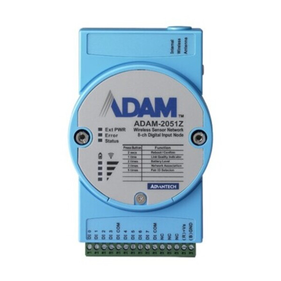
Page 39: Adam-2051Z
Storage Temperature: -40°C ~ 85°C (-40°F ~ 185°F) Digital Input: Channels: 8 Input Resistance: 10 KOhm Supports wet and dry contacts Input Level: – Logical level 0: 0 ~ 0.8 Vmax – Logical level 1:2.0 Vmin ~ 5.0 Vmax ADAM-2000 Series User Manual... -
Page 40: Adam-2051Pz
Storage Temperature: -40°C ~ 85°C (-40°F ~ 185°F) Digital Input: Channels: 8 Input Resistance: 10 KOhm Supports wet and dry contacts Input Level: – Logical level 0: 0 ~ 0.8 Vmax – Logical level 1: 2.0 Vmin ~ 5.0 Vmax ADAM-2000 Series User Manual... -
Page 41: Figure 3.3 Adam-2051Z/2051Pz Wet Contact Diagram
Application Wiring: Figure 3.3 ADAM-2051Z/2051PZ Wet Contact Diagram Figure 3.4 ADAM-2051Z/2051PZ Dry Contact Diagram ADAM-2000 Series User Manual... - Page 42 ADAM-2000 Series User Manual...
-
Page 43: Chapter 4 Installation Guide
Chapter Installation Guide... -
Page 44: Determining The Proper Environment
ADAM-2000 series module 2 dBi antenna (ADAM-2520Z, ADAM-2510Z, ADAM-2051PZ only) 2 x Mounting kits ADAM-2000 series CD (User manual, datasheet, Quick start guide and AdamA- pax .NET Utility) 4.1.2 System Requirements IBM PC compatible computer with at least 486 CPU (Pentium recommended) ... -
Page 45: Figure 4.1 The Architecture Of The Wireless Sensor Network
An End Device (End Node) is the basic element to acquire the physical signals and data from I/O, sensor and even communication interface. It can be designed for many different functions and is possible for standalone applications by battery-power. Figure 4.1 The Architecture of the Wireless Sensor Network ADAM-2000 Series User Manual... -
Page 46: Establish The Connection
4.2.1 Basic Installation In the side of the ADAM-2000 series, users can find Mode Switch and Function Button. The two hardware keys contain several combinations for device operations. The default position of Mode Switch is set in the Initial Mode to configure the device and establish connection for Normal Mode. - Page 47 Pair ID selection, the click N times according the Coordinator Pair ID, then hold the Function Button for 2 seconds to confirm your setting, finally press the Function Button 3 times to join a PAN. Error LED turns off when it join a PAN. ADAM-2000 Series User Manual...
-
Page 48: Figure 4.2 Multi-End Device Network Performance
The images below comparisons between Multi-End Device performance and the relationship between Multi-End Devices and Routers. Their purpose is to assist the user in installing the ADAM-2000 devices in a proper network configuration and oper- ation. Figure 4.2 Multi-End Device Network performance ADAM-2000 Series User Manual... -
Page 49: Adam-2000 Series Installation Flowcharts
4.2.2.1 ADAM-2000 Series Installation Overview The section describes how to host a WPAN for the ADAM-2000 series. The coordina- tor, end devices are basic component for the wireless data acquisition system. Rout- ers are optional to enhance the network coverage and mesh mechanism. Please refer to the following flowchart for the overview of the ADAM-2000 installation, config- uration and operation. -
Page 50: Figure 4.4 Adam-2000 Installation Chart
Normal Mode. Set the Coordinator, Routers and End Devices to Normal Mode. All the ADAM-2000 devices set in the same PAN and RF channel will automatically associate the PAN for data acquisition. Figure 4.4 ADAM-2000 Installation Chart ADAM-2000 Series User Manual... - Page 51 Amber LED turns Amber LED turns on on indicating Modbus indicating Pair ID. Open AdamApax.NET Utility to configure the Collect and transmit ADAM-2000 series, data/signal from end refer to Chapter 5 nodes to host. for more information. ADAM-2000 Series User Manual...
- Page 52 Successfully join a PAN signal from end nodes with default PAN ID and to coordinator. RF channel. Amber LED indicating Pair ID. Open AdamApax .NET Utility to configure the ADAM-2000 series, refer to Chapter 5 for more information. ADAM-2000 Series User Manual...
- Page 53 Successfully join a PAN Transmit data/signal to with default PAN ID and Coordinator. RF channel. Amber LED indicating Pair ID. Open AdamApax .NET Utility to configure the ADAM-2000 series, refer to Chapter 5 for more information. ADAM-2000 Series User Manual...
-
Page 54: Advanced Functions
3 LED ON, 1 LED Blink Excellent 80%~ 61% 2 LED ON, 1 LED Blink Good 60%~ 41% 1 LED ON, 1 LED Blink Normal 40%~ 21% 1 LED Blink Poor Below 21% No LED on, Error LED blinks Low battery ADAM-2000 Series User Manual... -
Page 55: Pairing
Button Function Table Table 4.3: Button Functions Press Button Function 2 Seconds Confirm the Pair ID 3 Seconds Reboot Once Link Quality Indicator 2 Times Battery Level 3 Times Network Association 5 Times Pair ID Selection ADAM-2000 Series User Manual... -
Page 56: Conduct A Site Survey
Walk away from the new added router and use the same way to add next router until the position of end-devices that will install can access the network. ADAM-2000 Series User Manual... -
Page 57: Chapter 5 Software Configuration Guide
Chapter Software Configuration Guide... -
Page 58: System Software Configuration Utility
System Software Configuration Utility The AdamApax .NET Utility software offers a graphical interface that helps you con- figure the ADAM-2000 series. It is also very convenient to test and monitor your remote data acquisition and control system. The following guidelines will give you some brief instructions on how to use this Utility. - Page 59 Help Menu: Check Up-to-Date on the Web - Choose this option, it will automatically connect to Advantech download website.You can download the latest utility there. About AdamApax .NET Utility- Choose this option, you can see version of AdamApax .NET Utility installed on your computer.
-
Page 60: Figure 5.2 Adamapax .Net Utility Toolbar
Wireless Sensor Networks The category contains the ADAM-2000 series. You can connect the ADAM- 2000 series, through the serial interface. The ADAM-2000 series will be listed for further configuration. Status Display Area Status Display area, on the right part of utility operation window, is the main screen for operation. -
Page 61: Usb Driver Installation
Then restart the AdamApax .NET Utility. 5.3.2 Search and Configure the ADAM-2000 Series The ADAM-2000 series can be searched and configured through AdamApax .NET Utility. Make sure the ADAM-2000 devices are installed properly in Initial Mode. For more information, please refer to the Chapter 4.2. -
Page 62: Figure 5.4 Search The Usb Interface Adam-2000 Devices On The Host Pc For The Virtual Com Port
Figure 5.4 Search the USB interface ADAM-2000 devices on the host PC for the virtual COM port. Click the COM port then click right button to select the "Search" to find the ADAM- 2000 devices. Figure 5.5 Search the COM port for the ADAM-2000 devices. ADAM-2000 Series User Manual... -
Page 63: Figure 5.6 Searching The Network Dialog
The ADAM-2000 coordinators will be listed on the Tree View of the selected COM port. Figure 5.7 Searching the ADAM-2000 coordinators. If you also want to connect ADAM-2000 series to utility at the same time, Make sure they are in initial mode Set PAN ID in the same group... -
Page 64: Figure 5.8 Adam-2000 Devices Lists On The Tree View And Infor Mation
(Gateway). Figure 5.8 ADAM-2000 devices lists on the Tree View and Information page. Note! When End Device and Router are set in same slave ID that modules tree view will be highlighted in yellow. ADAM-2000 Series User Manual... -
Page 65: Figure 5.9 The Overview Of Adam-2000 End Devices
Figure 5.9 The overview of ADAM-2000 end devices. Folder of ADAM-Router lists the ADAM-2000 routers in Tree View and List View of Router page. The page contains an overview of the routers and the status. Figure 5.10 The overview of ADAM-2000 routers ADAM-2000 Series User Manual... -
Page 66: Figure 5.11Information Page Of Adam-2520Z
Select the "Wireless Configuration" page. Set PAN ID and RF Channel to host a PAN for wireless communication in Nor- mal Mode. Set Slave ID for Modbus communication in Normal Mode. Figure 5.12 Wireless Configuration page of the ADAM-2520Z. ADAM-2000 Series User Manual... -
Page 67: Figure 5.13 Information Page Of Adam-2510Z
Click the ADAM-2510Z, it will display the Information, Wireless Configurations and Device Status. In the Information page, users can download the firmware to the ADAM-2510Z if there is any upgrade firmware from the Advantech. Figure 5.13 Information page of ADAM-2510Z In the Wireless Configuration page, set PAN ID and RF Channel to host a PAN for wireless communication in Normal Mode. -
Page 68: Figure 5.15 The Device Status Page Of The Adam-2510Z
Click the ADAM End device icon, it will display the Information and Wireless Configuration pages in Status Display area. In the Information page, user can download the firmware to the ADAM End device if have any upgrade firmware from Advantech. Figure 5.16 Information Page ADAM-2000 Series User Manual... -
Page 69: Figure 5.17Wireless Configuration
1 second to 1 day. Figure 5.17 Wireless Configuration page In the Device Status page, user can check the Module Status, Link Quality, Battery Status and External Power of a device. Figure 5.18 The Device Status page ADAM-2000 Series User Manual... -
Page 70: Figure 5.19The Signal
Under the non-interference environment and good level of LQI signal, firmware update for an end device would normally be completed in 3 minutes. ADAM-2000 Series User Manual... -
Page 71: Network Topology Of Adam-2000 Series
Router and the "E" represents the role of End Device. You can scroll position on the screen using a mouse. Figure 5.20 Topology of the ADAM-2000 series The function allows user to put a picture on the background and drag the compo- nents to any positions of the background. -
Page 72: Module Locate Function Of Adam-2000 Series (Except Adam- 2520Z)
5.3.4 Module Locate Function of ADAM-2000 Series (Except ADAM- 2520Z) Knowing where module positions are located is one of the most important things for users creating a network topology with a utility. In the initial mode, the AdamApax .NET utility supports locate function for user to find out where current module posi- tions are located. -
Page 73: Group Configuration
The firmware configuration option, can perform firmware updates for multiple end devices which users select. After selecting the types of modules and specifying the file source, the selected modules would be updated by sequence. Figure 5.24 Firmware Update in Group Configuration ADAM-2000 Series User Manual... -
Page 74: Figure 5.25Wireless Setting Of Group Configuration
The wireless setting option, can set the value of Slave ID and Data Cycle for multiple modules which users select. Figure 5.25 Wireless Setting of Group Configuration ADAM-2000 Series User Manual... -
Page 75: Chapter Aadam-2000 Series Functions
Appendix ADAM-2000 Series Functions... -
Page 76: Introduction
Introduction ADAM-2000 series supports Modbus RTU protocol and serves as Modbus slave devices that takes commands from a Modbus master. Each module has its own unique Modbus ID such that master can address each individual slave. The ADAM- 2000 series are the Modbus RTU ready communication solution for Wireless Sensor Network data acquisition applications. -
Page 77: Adam-2520Z
Read Bit 2: Disconnected Bit 3: Connecting 40310 Device Short Address Read 0x0000~0xFFFF Note! * It should be USB or battery power input. It does not recommend user to use battery as power source for ADAM-2520Z. ADAM-2000 Series User Manual... -
Page 78: Adam-2510Z
Bit 3: Connecting Data Cycle Time 40307 (Upper) 0x00000001~0x00015180 Read (1 ~ 864000 seconds) Data Cycle Time 40308 (Lower) 40309 LQI Percentage Read 0x0000~0x0064 (0~100%) 40310 Device Short Address Read 0x0000~0xFFFF 40311 Parent Address Read 0x0000~0xFFFF ADAM-2000 Series User Manual... -
Page 79: Adam-2017Pz
Read Firmware Version 2 (ex: 0x0003 means version B03) Bit 0: 0; Initial Mode Bit 0: 1; Normal Mode 40301 Module Status Read Bit 1: 0; No External Power Input Bit 1: 1; External Power Input ADAM-2000 Series User Manual... - Page 80 Bit 3: Connecting Data Cycle Time 40307 (Upper word) 0x00000001~0x00015180 Read (1 ~ 864000 seconds) Data Cycle Time 40308 (Lower word) 40309 LQI Percentage Read 0x0000~0x0064 (0~100%) 40310 Device Short Address Read 0x0000~0xFFFF 40311 Parent Address Read 0x0000~0xFFFF ADAM-2000 Series User Manual...
- Page 81 Open Circuit (Burn-Out) Reserved Not Converted Yet Reserved ADC Initializing Error Reserved Zero Span Calibration Error Reserved 10 ~ 15 *ADAM-2017PZ AI Status (2 Register at Low Address) Status Description Bit Order Reserved 0 ~ 15 ADAM-2000 Series User Manual...
-
Page 82: Adam-2031Z
0x0000~0x0064 (0~100%) 40310 Device Short Address Read 0x0000~0xFFFF 40311 Parent Address Read 0x0000~0xFFFF Note! The temperature T is calculated by inserting temperature signal output into the following formula (result is in – 46.85 ------ - 175.72x ADAM-2000 Series User Manual... - Page 83 Note! The humidity RH is calculated by inserting humidity signal output into the following formula (result is in %RH) – -------- - 125x ADAM-2000 Series User Manual...
-
Page 84: Adam-2051Z
Bit 3: Connecting Data Cycle Time 40307 (Upper) 0x00000001~0x00015180 Read (1 ~ 864000 seconds) Data Cycle Time 40308 (Lower) 40309 LQI Percentage Read 0x0000~0x0064 (0~100%) 40310 Device Short Address Read 0x0000~0xFFFF 40311 Parent Address Read 0x0000~0xFFFF ADAM-2000 Series User Manual... -
Page 85: Adam-2051Pz
Bit 3: Connecting Data Cycle Time 40307 (Upper) 0x00000001~0x00015180 Read (1 ~ 864000 seconds) Data Cycle Time 40308 (Lower) 40309 LQI Percentage Read 0x0000~0x0064 (0~100%) 40310 Device Short Address Read 0x0000~0xFFFF 40311 Parent Address Read 0x0000~0xFFFF ADAM-2000 Series User Manual... - Page 86 ADAM-2000 Series User Manual...
- Page 87 Appendix Troubleshooting...
-
Page 88: Chapter B Troubleshooting
A5: The ADAM-2520Z does not support the HW/SW flow control and the user appli- cation/software must turn off the HW/SW flow control. Q6: Can I use the rechargeable battery as the ADAM-2000 series power input? A6: The ADAM-2000 can not use rechargeable batteries. Besides, the battery will not be charged while using the external power. -
Page 89: Notice
The device must not be co-located or operating in conjunction with any other antenna or transmitter. The changes or modifications not expressly approved by the party responsible for compliance could void the user's authority to operate the equipment. ADAM-2000 Series User Manual... - Page 90 No part of this publication may be reproduced in any form or by any means, electronic, photocopying, recording or otherwise, without prior written permis- sion of the publisher. All brand and product names are trademarks or registered trademarks of their respective companies. © Advantech Co., Ltd. 2012...
Need help?
Do you have a question about the ADAM-2000 Series and is the answer not in the manual?
Questions and answers