Table of Contents
Advertisement
Quick Links
Our company network supports you worldwide with offices in Germany, Austria,
Switzerland, Great Britain and the USA. For more information please contact:
FORTEC Elektronik AG
Hauptniederlassung
Lechwiesenstr. 9
86899 Landsberg am Lech
Telefon:
+49 (0) 8191 91172-0
Telefax:
+49 (0) 8191 21770
E-Mail:
sales@fortecag.de
Internet:
www.fortecag.de
FORTEC Elektronik AG
Büro Wien
Nuschinggasse 12
A-1230 Wien
Telefon:
+43 1 8673492-0
Telefax:
+43 1 8673492-26
E-Mail:
office@fortec.at
Internet:
www.fortec.at
The information contained in this document has been carefully researched and is, to the best
of our knowledge, accurate. However, we assume no liability for any product failures or
damages, immediate or consequential, resulting from the use of the information provided
herein. Our products are not intended for use in systems in which failures of product could
result in personal injury. All trademarks mentioned herein are property of their respective
owners. All specifications are subject to change without notice.
Manual
SOM-5892
Advantech
FORTEC Elektronik AG
Büro West
Hohenstaufenring 55
50674 Köln
Telefon:
Telefax:
E-Mail:
Internet:
ALTRAC AG
(Tochter der FORTEC):
Bahnhofstraße 3
CH-5436 Würenlos
Telefon:
Telefax:
E-Mail:
Internet:
+49 (0) 221 272 273-0
+49 (0) 221 272 273-10
west@fortecag.de
www.fortecag.de
+41 (0) 44 7446111
+41 (0) 44 7446161
info@altrac.ch
www.altrac.ch
Advertisement
Table of Contents

Related Manuals for Advantech SOM-5892


Summary of Contents for Advantech SOM-5892
- Page 1 Manual SOM-5892 Advantech Our company network supports you worldwide with offices in Germany, Austria, Switzerland, Great Britain and the USA. For more information please contact: FORTEC Elektronik AG FORTEC Elektronik AG Hauptniederlassung Büro West Lechwiesenstr. 9 Hohenstaufenring 55 86899 Landsberg am Lech 50674 Köln...
- Page 2 User Manual SOM-5892...
- Page 3 No part of this manual may be reproduced, copied, translated or transmitted in any form or by any means without the prior written permission of Advantech Co., Ltd. Information provided in this manual is intended to be accurate and reliable. How- ever, Advantech Co., Ltd.
-
Page 4: Declaration Of Conformity
Class I, Division 2, Groups A, B, C and D indoor hazards. Technical Support and Assistance Visit the Advantech website at http://support.advantech.com where you can find the latest information about the product. Contact your distributor, sales representative, or Advantech's customer service center for technical support if you need additional assistance. - Page 5 Before setting up the system, check that the items listed below are included and in good condition. If any item does not accord with the table, please contact your dealer immediately. SOM-5892 CPU Module 1 x Heatspreader (1960055344N001) SOM-5892 User Manual...
-
Page 6: Safety Instructions
The sound pressure level at the operator's position according to IEC 704-1:1982 is no more than 70 dB (A). DISCLAIMER: This set of instructions is given according to IEC 704-1. Advantech disclaims all responsibility for the accuracy of any statements contained herein. - Page 7 Don't touch any components on the CPU card or other cards while the PC is on. Disconnect power before making any configuration changes. The sudden rush of power as you connect a jumper or install a card may damage sensitive elec- tronic components. SOM-5892 User Manual...
-
Page 8: Table Of Contents
3.2.2 Advanced BIOS Features Setup..........18 Figure 3.3 Advanced BIOS features setup screen ....18 Figure 3.4 Advantech BIOS Update V1.3 ........19 Figure 3.5 ACPI Settings ............20 Figure 3.6 Trusted Computing ........... 21 Figure 3.7 CPU Configuration............ 22 Figure 3.8 SATA Configuration.......... - Page 9 Installation..67 S/W Introduction ..................68 Driver Installation ..................68 4.2.1 Windows XP / Windows 7 Driver Setup........68 4.2.2 Other OS..................68 Advantech iManager ................69 Appendix A Watchdog Timer........ 71 Programming the Watchdog Timer ............72 Appendix B Programming GPIO......
-
Page 10: Chapter 1 General Information
Chapter General Information This chapter gives background information on the SOM-5892 CPU System on Module. Sections include: Introduction Specification Functional Block Diagram SOM-5892 Type 6-pin Assign- ment... -
Page 11: Introduction
Introduction SOM-5892 is a COM-Express Basic module with pin-out Type 6 that fully complies with the PICMG (PCI Industrial Computer Manufactures Group) COM.0 R2.0 specifi- cation. The CPU module builds Intel 3rd Generation Core i processor Ivy Bridge, PCH QM77, and other peripheral chips to fulfill COM specified functionalities. Intel... -
Page 12: Display
Expansion Interface PCI Express x16: Supports default 1 port PCIe x16 compliant to PCIe Gen2* (5.0 GT/s) specification, several configurable combinations may need BOM reworks. Please contact Advantech sales or FAE for more details. Default Option 1 Option 2 ... -
Page 13: I/O
Operating: 0 ~ 60° C (32 ~ 140 ° F) – Storage: -40 ~ 85° C (-40 ~ 185° F) Humidity Specification: – Operating: 40° C @ 95% relative humidity, non-condensing – Storage: 60° C @ 95% relative humidity, non-condensing SOM-5892 User Manual... -
Page 14: Functional Block Diagram
Functional Block Diagram SOM-5892 User Manual... -
Page 15: Som-5892 Type 6 Pin Assignment
This section gives SOM-5892 pin assignment on COM Express connector which compliant with COMR.0 R2.0 Type 6 pin-out definitions. More details about how to use these pins and get design references, please contact to Advantech for design guide, checklist, reference schematic, and other hardware/software support. - Page 16 PCIE_RX0+ PCIE_TX0- PCIE_RX0- LVDS_A0+ LVDS_B0+ LVDS_A0- LVDS_B0- LVDS_A1+ LVDS_B1+ LVDS_A1- LVDS_B1- LVDS_A2+ LVDS_B2+ LVDS_A2- LVDS_B2- LVDS_VDD_EN LVDS_B3+ LVDS_A3+ LVDS_B3- LVDS_A3- LVDS_BKLT_EN LVDS_A_CK+ LVDS_B_CK+ LVDS_A_CK- LVDS_B_CK- LVDS_I2C_CK LVDS_BKLT_CTRL LVDS_I2C_DAT VCC_5V_SBY GPI3 VCC_5V_SBY RSVD VCC_5V_SBY RSVD VCC_5V_SBY PCIE0_CK_REF+ BIOS_DIS1# SOM-5892 User Manual...
- Page 17 A106 VCC_12V B106 VCC_12V A107 VCC_12V B107 VCC_12V A108 VCC_12V B108 VCC_12V A109 VCC_12V B109 VCC_12V A110 B110 SOM-5892 Row C, D USB_SSRX0- USB_SSTX0- USB_SSRX0+ USB_SSTX0+ USB_SSRX1- USB_SSTX1- USB_SSRX1+ USB_SSTX1+ USB_SSRX2- USB_SSTX2- USB_SSRX2+ USB_SSTX2+ USB_SSRX3- USB_SSTX3- USB_SSRX3+ USB_SSTX3+ DDI1_PAIR6+ DDI1_AUX+...
- Page 18 PEG_RX0+ PEG_TX0+ PEG_RX0- PEG_TX0- TYPE0# PEG_LANE_RV# PEG_RX1+ PEG_TX1+ PEG_RX1- PEG_TX1- TYPE1# TYPE2# PEG_RX2+ PEG_TX2+ PEG_RX2- PEG_TX2- PEG_RX3+ PEG_TX3+ PEG_RX3- PEG_TX3- RSVD RSVD RSVD RSVD PEG_RX4+ PEG_TX4+ PEG_RX4- PEG_TX4- RSVD PEG_RX5+ PEG_TX5+ PEG_RX5- PEG_TX5- PEG_RX6+ PEG_TX6+ PEG_RX6- PEG_TX6- SOM-5892 User Manual...
- Page 19 D100 C101 PEG_RX15+ D101 PEG_TX15+ C102 PEG_RX15- D102 PEG_TX15- C103 D103 C104 VCC_12V D104 VCC_12V C105 VCC_12V D105 VCC_12V C106 VCC_12V D106 VCC_12V C107 VCC_12V D107 VCC_12V C108 VCC_12V D108 VCC_12V C109 VCC_12V D109 VCC_12V C110 D110 SOM-5892 User Manual...
-
Page 20: Chapter 2 Mechanical Information
Chapter Mechanical Information This chapter gives mechanical and connector information on the SOM-5892 CPU System on Mod- ule. Sections include: Board Information Mechanical Drawing... -
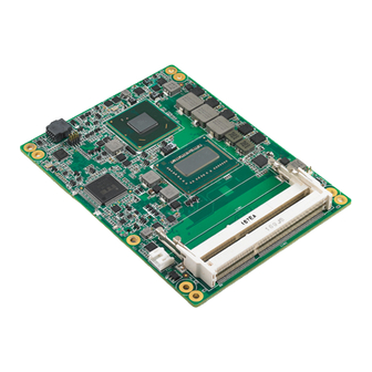
Page 21: Board Information
Board Information The figures below indicate the main chips on SOM-5892 Computer-on-Module. Please be aware on these positions while designing customer's own carrier board to avoid mechanical violence and thermal solutions for best thermal dispassion perfor- mance. DDR3 SODIMM Processor... -
Page 22: Mechanical Drawing
Mechanical Drawing For more detail about 2D/3D models, please find on Advantech COM support service website http://com.advantech.com. Figure 2.3 Board Mechanical Drawing - Front Figure 2.4 Board Mechanical Drawing - Back SOM-5892 User Manual... - Page 23 SOM-5892 User Manual...
-
Page 24: Chapter 3 Ami Bios
Chapter AMI BIOS Sections include: Introduction Entering Setup... -
Page 25: Introduction
AMIBIOS has been integrated into many motherboards for over a decade. With the AMIBIOS Setup program, users can modify BIOS settings and control various sys- tem features. This chapter describes the basic navigation of the SOM-5892 BIOS setup screens. Figure 3.1 Setup program initial screen AMI's BIOS ROM has a built-in Setup program that allows users to modify the basic system configuration. -
Page 26: Entering Setup
System Date using the <Arrow> keys. Enter new values through the keyboard. Press the <Tab> key or the <Arrow> keys to move between fields. The date must be entered in MM/DD/YY format. The time must be entered in HH:MM:SS format. SOM-5892 User Manual... -
Page 27: Advanced Bios Features Setup
3.2.2 Advanced BIOS Features Setup Select the Advanced tab from the SOM-5892 setup screen to enter the Advanced BIOS Setup screen. Users can select any item in the left frame of the screen, such as CPU Configuration, to go to the sub menu for that item. Users can display an Advanced BIOS Setup option by highlighting it using the <Arrow>... -
Page 28: Figure 3.4 Advantech Bios Update V1.3
3.2.2.1 Advantech BIOS Update V1.3 Figure 3.4 Advantech BIOS Update V1.3 Advantech BIOS Update V1.3 This item allows users to update BIOS flash ROM. SOM-5892 User Manual... -
Page 29: Figure 3.5 Acpi Settings
This item allows users to set the ACPI sleep state. Lock Legacy Resources This item allows users to lock legacy devices' resources. S3 Video Repost This item allows users to enable or disable S3 Video Repost. SOM-5892 User Manual... -
Page 30: Figure 3.6 Trusted Computing
3.2.2.3 Trusted Computing Figure 3.6 Trusted Computing TPM Support Disable/Enable TPM if available. SOM-5892 User Manual... -
Page 31: Figure 3.7 Cpu Configuration
This item allows users to enable or disable the intel virtualization technology. Hardware Prefetcher This item allows users to enable or disable the hardware prefetcher feature. Adjacent Cache Line Prefetch This item allows users to enable or disable the adjacent cache line prefetch fea- ture. SOM-5892 User Manual... -
Page 32: Figure 3.8 Sata Configuration
3.2.2.5 SATA Configuration Figure 3.8 SATA Configuration SATA Controller(s) This item allows users to enable or disable the SATA controller(s). SATA Mode Selection This item allows users to select mode of SATA controller(s). SOM-5892 User Manual... -
Page 33: Figure 3.9 Intel® Rapid Technology
3.2.2.6 Intel® Rapid Start Technology Figure 3.9 Intel® Rapid Technology Intel® Rapid Start Technology This item allows users to enable or disable Intel Rapid Start Technology. SOM-5892 User Manual... -
Page 34: Figure 3.10Intel Txt(Lt) Configuration
3.2.2.7 Intel TXT(LT) Configuration Figure 3.10 Intel TXT(LT) Configuration Secure Mode Extensions (SMX) This item allows users to enable or disable SMX. Intel TXT(LT) Support This item allows users to enable or disable Intel TXT. SOM-5892 User Manual... -
Page 35: Figure 3.11Pch-Fw Configuration
3.2.2.8 PCH-FW Configuration Figure 3.11 PCH-FW Configuration MDES BIOS Status Code This item allows users to enable or disable MDES BIOS Status Code function. SOM-5892 User Manual... -
Page 36: Figure 3.12Firmware Update Configuration
Firmware Update Configuration Figure 3.12 Firmware Update Configuration Me FW Image Re-Flash This item allows users to enable or disable Me FW image re-flash function. SOM-5892 User Manual... -
Page 37: Figure 3.13Intel® Anti-Theft Technology Configuration
Intel® Anti-Theft Technology Rec This item allows users to set the number of Recovery attempts allowed. Enter Intel AT Suspend Mode This item allows users to enable or disable to enter Intel AT suspend mode. SOM-5892 User Manual... -
Page 38: Figure 3.14Amt Configuration
This item allows users to enable or disable Alert Specification Format. Activate Remote Assistance Process This item allows users to enable or disable trigger CIRA boot. USB Configure This item allows users to enable or disable USB configure function. SOM-5892 User Manual... -
Page 39: Figure 3.15Usb Configuration
EHCI Hand-Off This is a workaround for the OS without EHCI hand-off support. The EHCI own- ership change should claim by EHCI driver. USB transfer time-out Set the time-out value for Control, Bulk, and Interrupt transfers. SOM-5892 User Manual... -
Page 40: Figure 3.16Smart Settings
Host Controller. 'Auto' uses default value: for a Root port it is 100 ms, for a Hub port the delay is taken from Hub descriptor. 3.2.2.12 SMART Settings Figure 3.16 SMART Settings SMART Self Test This item allows users to enable or disable HDDs SMART Self Test during POST. SOM-5892 User Manual... -
Page 41: Figure 3.17Embedded Controller Configuration
This item allows users to enable or disable EC serial port A. EC Serial Port B This item allows users to enable or disable EC serial port B. Backlight Function This item allows users to set backlight Function. SOM-5892 User Manual... -
Page 42: Figure 3.18Intel® Smart Connect Technology
3.2.2.14 Intel® Smart Connect Technology Figure 3.18 Intel® Smart Connect Technology ISCT Configuration This item allows users to enable or disable ISCT Configuration. SOM-5892 User Manual... -
Page 43: Figure 3.19Super Io Configuration
3.2.2.15 Super IO Configuration Figure 3.19 Super IO Configuration SOM-5892 User Manual... -
Page 44: Figure 3.20Serial Port 0 Configuration
This item allows users to configure serial port 0. Figure 3.20 Serial Port 0 Configuration Serial Port Serial port 0 enable or disable Change settings Serial port 0 IRQ/IO/mode resources configuration. Users can choose IRQ,IO, and MODE. SOM-5892 User Manual... -
Page 45: Figure 3.21Serial Port 1 Configuration
This item allows users to configure serial port 1. Figure 3.21 Serial Port 1 Configuration Serial Port Serial port 1 enable or disable Change settings Serial port 1 IRQ/IO/mode resources configuration. Users can choose IRQ,IO, and MODE. SOM-5892 User Manual... -
Page 46: Figure 3.22Parallel Port Configuration
Figure 3.22 Parallel Port Configuration Parallel Port This item allows to enable or disable parallel port Change Settings This item allow parallel port resources include IRQ/IO configuration. Device Mode Set parallel mode as EPP/ECP/STD/SPP SOM-5892 User Manual... -
Page 47: Figure 3.23Serial Port Console Redirection
3.2.2.16 Serial Port Console Redirection Figure 3.23 Serial Port Console Redirection Console Redirection This item allows users to enable or disable console redirection for Microsoft Windows Emergency Management Services (EMS). SOM-5892 User Manual... -
Page 48: Figure 3.24Console Redirection Settings
Bits per second Selects serial port transmission speed. The speed must be matched on the other side. Long or noisy lines may require lower speeds. – Flow Control Flow control can prevent data loss from buffer overflow. SOM-5892 User Manual... -
Page 49: Figure 3.25Cpu Ppm Configuration
This item allows users to enable or disable CPU C-state support. Config TDP LOCK This item allows users to enable or disable Config TDP LOCK. ACPI T State This item allows users to enable or disable ACPI T State. SOM-5892 User Manual... -
Page 50: Figure 3.26Switchable Graphics
3.2.2.18 Switchable Graphics Figure 3.26 Switchable Graphics SG Mode Select This item allows users to select switchable graphics mode. SOM-5892 User Manual... -
Page 51: Figure 3.27Sandybridge Dts Configuration
3.2.2.19 Sandybridge DTS Configuration Figure 3.27 Sandybridge DTS Configuration CPU DTS This item allows users to enable or disable CPU DTS. SOM-5892 User Manual... -
Page 52: Chipset
3.2.3 Chipset Select the Chipset tab from the SOM-5892 setup screen to enter the Chipset BIOS Setup screen. You can display a Chipset BIOS Setup option by highlight- ing it using the <Arrow> keys. All Plug and Play BIOS Setup options are described in this section. -
Page 53: Figure 3.29Pch-Io Configuration
Enables or disables the high precision timer. SLP_S4 Assertion Width This item allows users to set a delay of sorts. Restore AC Power Loss This item allows users to select off, on and last state. SOM-5892 User Manual... -
Page 54: Figure 3.30Pci Express Configuration
PCI Express Configuration Figure 3.30 PCI Express Configuration PCI Express Root Port x This item allows users to configure PCI express ports. SOM-5892 User Manual... -
Page 55: Figure 3.31Pci Express Root Port 1
Extra Bus Reserved Extra bus Reserved for bridges behind this root bridge. Reserved Memory Reserved Memory Range for this root bridge Prefetchable Memory Prefetchable Memory Range for this root bridge. Reserved I/O Reserved I/O Range for this root bridge. SOM-5892 User Manual... -
Page 56: Figure 3.32Pci Express Root Port 2
Extra Bus Reserved Extra bus Reserved for bridges behind this root bridge. Reserved Memory Reserved Memory Range for this root bridge. Prefetchable Memory Prefetchable Memory Range for this root bridge. Reserved I/O Reserved I/O Range for this root bridge. SOM-5892 User Manual... -
Page 57: Figure 3.33Pci Express Root Port 3
Extra Bus Reserved Extra bus Reserved for bridges behind this root bridge. Reserved Memory Reserved Memory Range for this root bridge. Prefetchable Memory Prefetchable Memory Range for this root bridge. Reserved I/O Reserved I/O Range for this root bridge. SOM-5892 User Manual... -
Page 58: Figure 3.34Pci Express Root Port 4
Extra Bus Reserved Extra bus Reserved for bridges behind this root bridge. Reserved Memory Reserved Memory Range for this root bridge. Prefetchable Memory Prefetchable Memory Range for this root bridge. Reserved I/O Reserved I/O Range for this root bridge. SOM-5892 User Manual... -
Page 59: Figure 3.35Pci Express Root Port 5
Extra Bus Reserved Extra bus Reserved for bridges behind this root bridge. Reserved Memory Reserved Memory Range for this root bridge. Prefetchable Memory Prefetchable Memory Range for this root bridge. Reserved I/O Reserved I/O Range for this root bridge. SOM-5892 User Manual... -
Page 60: Figure 3.36Pci Express Root Port 7
Extra Bus Reserved Extra bus Reserved for bridges behind this root bridge. Reserved Memory Reserved Memory Range for this root bridge. Prefetchable Memory Prefetchable Memory Range for this root bridge. Reserved I/O Reserved I/O Range for this root bridge. SOM-5892 User Manual... -
Page 61: Figure 3.37Pci Express Root Port 8
Extra Bus Reserved Extra bus Reserved for bridges behind this root bridge. Reserved Memory Reserved Memory Range for this root bridge. Prefetchable Memory Prefetchable Memory Range for this root bridge. Reserved I/O Reserved I/O Range for this root bridge. SOM-5892 User Manual... -
Page 62: Figure 3.38Usb Configuration
XHCI Streams Enable or disable XHCI Maximum Primary Stream Array Size. – EHCI1/EHCI2 Enables or disables the EHCI controller. – USB Ports Per-Port Disable Control This item allows users to enable or disable each USB port individually. SOM-5892 User Manual... -
Page 63: Figure 3.39Pch Azalia Configuration
PCH Azalia Configuration Figure 3.39 PCH Azalia Configuration – Azalia This item allows to enable or disable PCH Azalia controller – Azalia Internal HDMI Codec Enables or disables the Azalia internal HDMI codec. SOM-5892 User Manual... -
Page 64: Figure 3.40System Agent (Sa) Configuration
3.2.3.2 System Agent (SA) Configuration Figure 3.40 System Agent (SA) Configuration VT-d This item allows users to enable or disable VT-d. DDR Selection This item allows users to select which DDR or DDRL voltage. SOM-5892 User Manual... -
Page 65: Figure 3.41Intel Igfx Configuration
This item allows users to select DVMT total memory size. – Gfx Low Power Mode This item allows users to enable or disable IGD low power mode. – Graphics Performance Analyzers This item allows users to enable or disable Graphics Performance Analyzers SOM-5892 User Manual... -
Page 66: Figure 3.42Lcd Control
Select boot display device at post stage. LCD Panel Type This item allows users to select panel resolution. Panel Scaling This item allows users to enable or disable panel scaling. Active LFP This item allows users to select LFP configuration. SOM-5892 User Manual... -
Page 67: Figure 3.43Nb Pcie Configuration
Gen3 Eq Phase 2 Perform PEG Equalization phase 2. Gen3 Eq Preset Search Perform PEG Gen3 Preset Search algorithm. Fast PEG Init Enable or disable Fast PEG Initial. RxCEM Loop back Enable or disable RxCEM Loop back. SOM-5892 User Manual... -
Page 68: Figure 3.44Peg Gen3 Root Port Preset Value For Each Lane
PEG Gen3 Root Port Preset Value for each Lane Figure 3.44 PEG Gen3 Root Port Preset Value for each Lane PEG Gen3 Root Port Preset Value for each Lane Value for Lane x from 1-11, default as 8. SOM-5892 User Manual... -
Page 69: Figure 3.45Peg Gen3 Endpoint Preset Value Each Lane
PEG Gen3 Endpoint Preset Value each Lane Figure 3.45 PEG Gen3 Endpoint Preset Value each Lane PEG Gen3 Endpoint Preset value each Lane Value for Lane x from 0 - 11, default as 7. SOM-5892 User Manual... -
Page 70: Figure 3.46Peg Gen3 Endpoint Hint Value Each Lane
PEG Gen3 Endpoint Hint Value each Lane Figure 3.46 PEG Gen3 Endpoint Hint Value each Lane PEG Gen3 Endpoint Hint Value each Lane Value for Lane x from 0 - 7, default as 2. SOM-5892 User Manual... -
Page 71: Boot Settings
RT code is executed above 1MB. Option ROM Message Set display mode for option ROM. Interrupt 19 Capture This item allows option ROMs to trap interrupt 19. 1st/2nd/3rd/4th/5th/6th/7th Boot This item allows users to set boot device priority. SOM-5892 User Manual... -
Page 72: Security Setup
Security Setup Figure 3.48 Password Configuration Select Security Setup from the SOM-5892 Setup main BIOS setup menu. All Security Setup options, such as password protection is described in this section. To access the sub menu for the following items, select the item and press <Enter>:... -
Page 73: Save & Exit
Restore Defaults The SOM-5892 automatically configures all setup items to optimal settings when users select this option. Optimal Defaults are designed for maximum sys- tem performance, but may not work best for all computer applications. In partic- ular, do not use the Optimal Defaults if the user's computer is experiencing system configuration problems. - Page 74 Save User Defaults When users have completed system configuration, select this option to save changes as user defaults without exit BIOS setup menu. Restore User Defaults The users can select this option to restore user defaults. SOM-5892 User Manual...
- Page 75 SOM-5892 User Manual...
-
Page 76: S/W Introduction
Chapter S/W Introduction & Installation Sections include: S/W Introduction Driver Installation Advantech iManger... -
Page 77: S/W Introduction
S/W Introduction The mission of Advantech Embedded Software Services is to "Enhance quality of life with Advantech platforms and Microsoft Windows embedded technology." We enable Windows Embedded software products on Advantech platforms to more effectively support the embedded computing community. Customers are freed from the hassle of dealing with multiple vendors (Hardware suppliers, System integrators, Embedded OS distributor) for projects. -
Page 78: Advantech Imanager
It makes these embedded features easier to integrate, speed up develop- ing schedule, and provide the customer's software continuity while upgrade hard- ware. More detail of how to use the APIs and utilities, please refer to Advantech iManager 2.0 Software API User Manual. - Page 79 SOM-5892 User Manual...
-
Page 80: Watchdog Timer
Appendix Watchdog Timer This appendix gives you the infor- mation about the watchdog timer programming on the SOM-5892 CPU System on Module. Sections include: Watchdog Timer Programming... -
Page 81: Programming The Watchdog Timer
Programming the Watchdog Timer Trigger Event Note IRQ7, 9, 11 (default disable) IRQ can be set in BIOS Power button event Power Off Support H/W Restart Support External WDT For details, please refer to iManager & Software API User Manual. SOM-5892 User Manual... -
Page 82: Programming Gpio
Appendix Programming GPIO This Appendix gives the illustra- tion of the General Purpose Input and Output pin setting. Sections include: System I/O ports... -
Page 83: Gpio Register
GPIO Register GPIO Byte Mapping H/W Pin Name bit0 GPO0 bit1 GPO1 bit2 GPO2 bit3 GPO3 bit4 GPI0 bit5 GPI1 bit6 GPI2 bit7 GPI3 For details, please refer to iManager & Software API User Manual. SOM-5892 User Manual... -
Page 84: System Assignments
Appendix System Assignments This appendix gives you the infor- mation about the system resource allocation on the SOM-5892 CPU System on Module. Sections include: System I/O ports DMA Channel Assignments Interrupt Assignments 1st MB Memory Map... -
Page 85: System I/O Ports
03B0-03BB VGASAVE 03C0-03DF VGASAVE 03F8-03FF Communications Port (COM1) 0400-0453 Motherboard resources 0454-0457 Motherboard resources 0458-047F Motherboard resources 04D0-04D1 Programmable interrupt controller 0500-057F Motherboard resources 0680-069F Motherboard resources 0778-077F ECP Printer Port (LPT1) 0A79-0A79 ISAPNP Read Data Port SOM-5892 User Manual... -
Page 86: Dma Channel Assignments
Standard Dual Channel PCI IDE Controller F120-F123 Standard Dual Channel PCI IDE Controller F130-F137 Standard Dual Channel PCI IDE Controller FFFF-FFFF Motherboard resources DMA Channel Assignments Table C.2: DMA Channel Assignments Channel Function ECP Printer Port (LPT1) Direct memory access controller SOM-5892 User Manual... -
Page 87: Interrupt Assignments
High precision event timer FED10000-FED17FFF Motherboard resources FED18000-FED18FFF Motherboard resources FED19000-FED19FFF Motherboard resources FED1C000-FED1FFFF Motherboard resources FED20000-FED3FFFF Motherboard resources FFE40000-FED44FFF System board FED45000-FED8FFFF Motherboard resources FED90000-FED93FFF Motherboard resources FEE00000-FEEFFFFF Motherboard resources FF000000-FFFFFFFF Intel 82802 Firmware Hub Device SOM-5892 User Manual... - Page 88 Appendix C System Assignments...
- Page 89 No part of this publication may be reproduced in any form or by any means, electronic, photocopying, recording or otherwise, without prior written permis- sion of the publisher. All brand and product names are trademarks or registered trademarks of their respective companies. © Advantech Co., Ltd. 2012...
- Page 90 Our company network supports you worldwide with offices in Germany, Austria, Switzerland, Great Britain and the USA. For more information please contact: FORTEC Elektronik AG FORTEC Elektronik AG Hauptniederlassung Büro West Lechwiesenstr. 9 Hohenstaufenring 55 86899 Landsberg am Lech 50674 Köln Telefon: +49 (0) 8191 91172-0 Telefon:...
Need help?
Do you have a question about the SOM-5892 and is the answer not in the manual?
Questions and answers