Advertisement
Quick Links
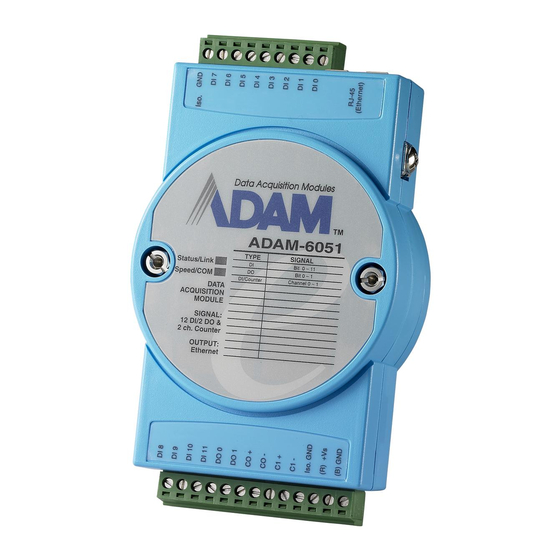
ADAM-6051 16-channel Digital I/O w/Counter Module
The ADAM-6051W is a high-density I/O module built-in a 10/100 based-T interface for seamless Ethernet connectivity.
It provides 12 digital input, 2 digital output, and 2 counter (10 KHz) channels with 5000V
Isolating protection. All of
RMS
the Digital Input channels support input latch function for important signal handling. Mean while, these DI channels
allows to be used as 1 KHz counter. Opposite to the intelligent DI functions, the Digital Output channels also support
pulse output function.
ADAM-6051W
Figure 1: ADAM-6051W 16-channel Digital I/O w/Counter Module
Advertisement

Related Manuals for Advantech ADAM-6051


Summary of Contents for Advantech ADAM-6051
- Page 1 ADAM-6051 16-channel Digital I/O w/Counter Module The ADAM-6051W is a high-density I/O module built-in a 10/100 based-T interface for seamless Ethernet connectivity. It provides 12 digital input, 2 digital output, and 2 counter (10 KHz) channels with 5000V Isolating protection. All of the Digital Input channels support input latch function for important signal handling.
- Page 2 ADAM-6051W Specification • Channel: 16 • I/O type: 12DI / 2DO / 2Counter • Digital Input: Dry Contact: Logic level 0: Close to GND Logic level 1: Open Wet Contact: Logic level 0: +3 V max Logic level 1: +10 to 30 V •...
- Page 3 Application Wiring Figure 2: ADAM-6051W Digital Input (Wet Contact) Wiring Figure 3: ADAM-6051W Digital Input (Wet Contact) Wiring...
- Page 4 Figure 4: ADAM-6051W Digital Output and Counter Wiring...
-
Page 5: System Architecture
System Architecture... - Page 6 ADAM-6051W Configuration Network Configuration Step 1 : Please open the ADAM-5000TCP-6000 utility software. The utility software will automatically scan the ADAM-6000 modules. Please wait for the ADAM-6051W being found by utility software. Step 2 : Please go the “Network” page to change the IP address/Subnet Address/Default Gateway of ADAM-6051W module to be compatible with user’s existing network and set the host idle time out value (the ADAM-6000 module can only accept 8 connection from host station.
- Page 7 Step 3 : Re-configuring the IP address of the configuration PC to be the original setting (compatible with user’s existing network) then re-start the utility software. The software will automatically search the ADAM-6051W module again. Step 4 : Go to the “Wireless” page to set the wireless LAN configuration. Please set the wireless LAN mode to be “Infrastructure”...
- Page 8 Please assign the SSID for the specific wireless AP to be connected with ADAM-6000W modules. User can place “ANY” key to let the ADAM-6000W modules to automatically search the existing wireless AP. Or key in the specific SSID to assign the dedicated AP (strongly recommending to set up the dedicated SSID, it can guarantee the communication of ADAM-6000W modules to be stable) For assigning the dedicated wireless LAN AP, user can use the site survey function to check the existing AP in connection environment.
- Page 9 Selecting the AP in the searching result table. Press “Apply” bottom to accept the AP to finish the set up action.
- Page 10 Please select the region for your area. Setting the used channel, the channel number must be included in the channel segment of your region. Please select the basic rate for the communication bandwidth.
- Page 11 Press the “Apply” bottom to finish the set up work. Step 5 : Configure the WEP security setting. Please go to the WEP page in “Wireless” of utility software. If user want to use the WEP security function, please enable the WEP function in “User WEP” then select the Key format and key in the WEP key for this requirement.
- Page 12 Step 6 : Data Stream Configuration In addition to TCP/IP communication protocol, ADAM-6000 supports UDP communication protocol to regularly broadcast data to specific host PCs. Click the tab of Data Stream, then configure the broadcasting interval and the specific IP addresses which need to receive data from the specific ADAM-6000 I/O module.
- Page 13 Data Stream Monitoring After finishing the configuration of Data Stream, you can select the item “Monitor Data Stream” in the function bar or click icon to call up operation display as below Figure. Select the IP address of the ADAM-6000 you want to read data, then click “Start ” button. The Utility software will begin to receive the stream data on this operation display.
- Page 14 Firmware/Web Page Configuration Step 1 : Please go to the “Firmware/Web” configuration page Step 2 : The ADAM-6000W modules support the configurable web page feature. Users don’t have to learn the Java language to write the Java program to make the customized web page. Users can use the utility software to easily configure the web page that you want.
- Page 15 Key in the Tag Name of input channel. Key in the description of input channel Press the label bottom to configure the label description of input channel.
- Page 16 Key in the Tag Name of output channel Key in the description of output channel...
- Page 17 Press the label bottom to configure the label description of output channel...
- Page 18 Key in the Tag Name of counter channel Key in the description of counter channel...
- Page 19 Click the title position to configure the page title description Please press “OK” after finishing all of the web page configuration. Press “Update” bottom to download the web page configuration into ADAM-6000W module. And system will save the configuration data as a file in C:\Programs\ADAM-5000TCP-6000 Utility\Program\Firmware\ADAM-6051W\ADAM6051W.Html...
- Page 20 User can also retrieve the previous web page configuration file to download to ADAM-6000W Module.
- Page 21 Select the stored web page configuration file then press “Open” Follow the above action to download the selected file into ADAM-6000W module.
- Page 22 Firmware Update Step 1 : Press the browse bottom of firmware Step 2 : Select the firmware file to be downloaded Step 3 : Press “Update” bottom to finish the firmware update action...
- Page 23 Input/Output Channel Configuration Step 1 : Please click on the “6051W” to go to the ADAM-6051W configuration main page. Step 7 : Please go to “Communication WDT” to set up the communication watchdog timer setting. This function is used for security protect, it means sometimes, noise or other reasons will cause the communication fail, and the host PC won’t control the modules anymore, but the modules will keep the latest output status, and this status may cause dangerous, so while this situation happen, the communication WDT will detect it till timeout then reset the module and set the output to safety value to...
- Page 24 Step 3 : Please click on “DO:XX” to access the digital output channel configuration page. The digital output channel of ADAM-6051W can be configured as typical DO output, pulse output, DO with LO to Hi delay or DO with Hi to LO delay: For typical DO setting : For Pulse Output setting :...
- Page 25 For “Lo to Hi delay” and “Hi to Lo delay” function :...
- Page 26 Step 4 : Please click on “DI:XX” to access the digital input configuration page. The digital input channel of ADAM-6068 supports typical DI, counter, frequency, Lo to Hi Latch and Hi to Lo Latch. For typical DI setting : For Counter setting :...
- Page 27 For Frequency setting :...
- Page 28 For “Lo to Hi Latch” and “Hi to Lo Latch” setting :...
- Page 29 Step 4 : Please click on “CNT:XX” to access the counter channel configuration page. For Counter setting : For Frequency Mode setting :...
- Page 30 Appendix : Adam-6000W Mode Setting switch Mode 1 (Normal Mode): In this mode, you can use Utility to configure module to Infrastructure or Ad hoc mode. Mode 2 (Diagnostic Mode): The purpose of this mode is used to recover the Adam-6000W module from error state.
- Page 31 Assigning addresses for the ADAM-6051W Modules ADDR 0X ITEM Attribute ADDR 4X ITEM Attribute 00001 40001~40002 *Counter *Counter 00002 40003~40004 *Counter 00003 40005~40006 *Counter 00004 40007~40008 *Counter 00005 40009~40010 *Counter 00006 40011~40012 *Counter 00007 40013~40014 *Counter 00008 40015~40016 *Counter 00009 40017~40018 *Counter 00010...
- Page 32 Counter 00045 Start(1)/Stop(0) 00046 Clear Counter(1) 00047 Clear Overflow Latch Status/ Clear 00048 Status Counter 00049 Start(1)/Stop(0) 00050 Clear Counter(1) 00051 Clear Overflow Latch Status/ Clear 00052 Status Counter 00053 Start(1)/Stop(0) 00054 Clear Counter(1) 00055 Clear Overflow Latch Status/ Clear 00056 Status Counter...
- Page 33 Counter 00077 Start(1)/Stop(0) 00078 Clear Counter(1) 00079 Clear Overflow Latch Status/ Clear 00080 Status Counter 00081 Start(1)/Stop(0) 00082 Clear Counter(1) 00083 Clear Overflow Latch Status/ Clear 00084 Status Counter 00085 Start(1)/Stop(0) 00086 Clear Counter(1) 00087 Clear Overflow Latch Status/ Clear 00088 Status *Note : How to retrieve the counter/frequency value on Modbus address mapping...
- Page 34 This equipment has been tested and found to comply with the limits for a Class B digital device, pursuant to part 15 of the FCC rules. These limits are designed to provide reasonable protection against harmful interference in a residential installation. This equipment generates, uses and can radiate radio frequency energy and, if not installed and used in accordance with the instructions, may cause harmful interference to radio communications.
Need help?
Do you have a question about the ADAM-6051 and is the answer not in the manual?
Questions and answers