Table of Contents
Advertisement
Advertisement
Table of Contents

Subscribe to Our Youtube Channel
Related Manuals for Advantech ADAM 4000 Series


Summary of Contents for Advantech ADAM 4000 Series
- Page 1 ADAM 4000 Series Data Acquisition Modules User's Manual...
- Page 3 Data Acquisition Modules User's Manual Copyright Notice This document is copyrighted, 1997, by Advantech Co., Ltd. All rights are reserved. Advantech Co., Ltd., reserves the right to make improvements to the products described in this manual at any time without notice.
-
Page 4: Table Of Contents
Table of Contents Chapter 1 Introduction ..............1-1 Overview ....................1-2 Applications ..................1-4 Chapter 2 Installation Guideline ..........2-1 System Requirements to set up an ADAM network ......2-3 Basic configuration and hook-up ............2-6 Baud rate and Checksum ..............2-9 Multiple Module Hookup .............. - Page 5 Digital I/O and Relay Output Module Command ......4-151 Counter/Frequency Module Command ........... 4-167 4.7.1 Configuration, Counter Input and Display Command Set ..4-167 4.7.2 Counter Setup Command Set ..........4-179 4.7.3 Digital Filter and Programmable Threshold Command Set .. 4-189 4.7.4 Digital Output and Alarm Command Set .........
- Page 6 B.2 Analog Input Ranges ................B-8 B.3 Analog Output Formats ..............B-13 B.3.1 Engineering Units ..............B-13 B.3.2 Percent of Span ................. B-14 B.3.3 Hexadecimal ................B-14 B.4 Analog Output Ranges ..............B-15 Appendix C Technical Diagrams ..........C-1 C.1 ADAM Dimensions ................C-2 C.2 Installation ...................
-
Page 7: Chapter 1 Introduction
Introduction... -
Page 8: Overview
, they accept any power unit that supplies power within the range of +10 to +30 V . The power supply ripple must be limited to 5 V peak-to-peak, and the immediate ripple voltage should be maintained between +10 and +30 V ADAM 4000 Series User's Manual... - Page 9 Chapter Connectivity and Programming ADAM modules can connect to and communicate with all computers and terminals. They use RS-485 transmission standards, and communicate with ASCII format commands. The command set for every module type consists of approximately ten different commands. The command set for input modules is larger because it incorporates alarm functions.
-
Page 10: Applications
1.2 Applications • Remote data acquisition • Process monitoring • Industrial process control • Energy managment • Supervisory control • Security systems • Laboratory automation • Building automation • Product testing • Direct digital control ADAM 4000 Series User's Manual... -
Page 11: Chapter 2 Installation Guideline
Installation Guideline... - Page 12 ADAM modules should not be opened. There is no need to open the ADAM modules: all configuration is done remotely and there are no user serviceable parts are inside. Opening the cover will therefore void the warranty. ADAM 4000 Series User's Manual...
-
Page 13: System Requirements To Set Up An Adam Network
Chapter 2.1 System Requirements to set up an ADAM network The following list gives an overview of what is needed to setup, install and configure an ADAM environment. • ADAM modules • A host computer, such as an IBM PC/AT compatible, that can output ASCII characters with an RS-232C or RS-485 port. - Page 14 In addition to serious voltage drops, long voltage lines can also cause interference with communication wires. Figure 2-1 Power Supply Connections We advise that the following standard colors (as indicated on the modules) be used for power lines: Black ADAM 4000 Series User's Manual...
- Page 15 Chapter Communication Wiring We recommend that shielded-twisted-pair cables that comply with the EIA RS-485 standard be used with the ADAM network to reduce interference. Only one set of twisted-pair cables is required to transmit both Data and RTS signals. We advice that the following standard colors (as indicated on the modules) be used for the communication lines: DATA+ Yellow...
-
Page 16: Basic Configuration And Hook-Up
Figure 2-2 Basic Hook-up of ADAM Module to Host Switches The following items are required to configure a module: an ADAM converter module, a personal computer with RS-232 port (baud rate set to 9600) and the ADAM utility software. ADAM 4000 Series User's Manual... - Page 17 Chapter Configuration with the ADAM Utility Software The easiest way to configure the ADAM module is by using the ADAM utility software: an easy-to-use menu-structured program will guide you through every step of the configuration. (See Appendix D, Utility Soft- ware) Configuration with the ADAM command set ADAM modules can also be configured by issuing direct commands from...
- Page 18 After reconfiguration, all modules should be powered down and powered up to force a reboot and let the changes take effect. See the next page for a strategy for changing baud rate and or checksum for an entire network. ADAM 4000 Series User's Manual...
-
Page 19: Baud Rate And Checksum
Chapter 2.3 Baud rate and Checksum Adam modules contain EEPROMs to store configuration information and calibration constants. The EEPROM replaces the usual array of switches and pots required to specify baud rate, input/output range etc. All of the ADAM modules can be configured remotely through their communication ports, without having to physically alter pot or switch settings. - Page 20 • Wait at least 7 seconds to let self calibration and ranging take effect. • Check the settings (If the baud rate has changed, the settings on the host computer should be changed accordingly). 2-10 ADAM 4000 Series User's Manual...
-
Page 21: Multiple Module Hookup
Chapter 2.4 Multiple Module Hookup The Figure below shows how ADAM modules are connected in a multiple module example: Figure 2-4 Multi-module Connection Chapter 2 Installation Guideline 2-11... -
Page 22: Application Example
In this application the HI alarm output is still available to activate an alarm or generate an emergen- cy shut-down if the temperature gets out of control. 2-12 ADAM 4000 Series User's Manual... - Page 23 Chapter Figure 2-5 Simple ON/OFF Controller Function Chapter 2 Installation Guideline 2-13...
- Page 24 The following program is a simple program written in BASIC that resem- bles our application example. The program first configures the ADAM- 4011 module to act as an ON/OFF controller and then monitors and displays the process temperature. 2-14 ADAM 4000 Series User's Manual...
- Page 25 Chapter Chapter 2 Installation Guideline 2-15...
- Page 26 Installation Guideline 2-16 ADAM 4000 Series User's Manual...
-
Page 27: Chapter 3 I/O Modules
I/O Modules... -
Page 28: Adam-4011/4011D/4012/4013/4015 Analog Input Modules
They can control solid-state relays which in turn may control heaters, pumps, and other electrical powered equipment. The digital inputs may be read by the host computer and used to sense the state of a remote digital signal. 3 - 2 ADAM 4000 Series User's Manual... - Page 29 Chapter Event counting (Except ADAM-4013) The event counter is connected to the Digital Input channel and can be used to keep track of the total amount of external low-speed pulses. Its accumulated maximal count is 65535. The number 65535 is held, even if the actual number of events exceeds 65535.
- Page 30 Finally, the on-board switching regulator accepts voltage between +10 and +30 V . This power circuit has an isolation value of 500 V to protect your equipment from damage from power surges. 3 - 4 ADAM 4000 Series User's Manual...
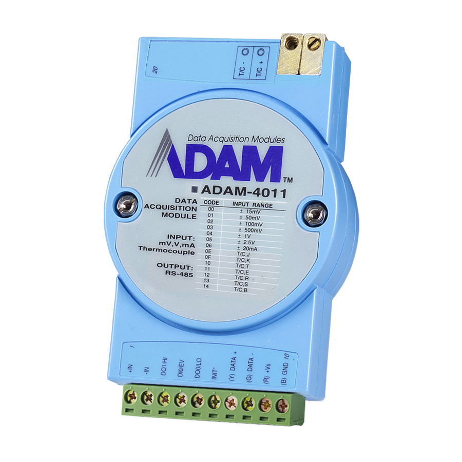
- Page 31 Chapter ADAM-4011 Figure 3-1 ADAM-4011 Thermocouple Input Module Accepts: - J, K, T, E, R, S and B thermocouples - millivolt inputs: ±15 mV, ±50 mV, ±100 mV and ±500 mV - Volt inputs: ±1 V and ±2.5 V - Current input: ±20 mA (Requires a 125 Ω resistor) Two digital output channels and one digital input channel are provided.
- Page 32 Depending on the module’s configuration setting, it can forward the data to the host computer in one of the following formats: - engineering units ( C, mV, V, or mA) - percent of full-scale range (FSR) - twos complement hexadecimal 3 - 6 ADAM 4000 Series User's Manual...
- Page 33 Chapter ADAM-4012 Figure 3-3 ADAM-4012 Analog Input Module Accepts: - millivolt inputs ± 150 mV and ±500 mV - volt inputs: ±1 V, ±5 V and ±10 V - current input: ±20 mA (requires a 125 Ω resistor) Two digital output channels and one digital input channel are provided. Depending on the module's configuration setting, it can forward the data to the host computer in one of the following formats: - engineering units (mV, V, or mA )
- Page 34 Depending on the module’s configuration setting, it can forward the data to the host computer in one of the following formats: - engineering units ( °C ) - percent of full-scale range (FSR) - twos complement hexadecimal 3 - 8 ADAM 4000 Series User's Manual...
- Page 35 Chapter Application Wiring The following gives you examples how to connect various types of analog inpuit and high-low alarm applications to your ADAM modules. Figure 3-5 Millivolt and Volt Input Figure 3-6 Thermocouple Input Chapter 3 I/O Modules...
- Page 36 I/O Modules Figure 3-7 Process Current Input Figure 3-8 Digital Output used with SSR (HI-LO alarm) 3-10 ADAM 4000 Series User's Manual...
- Page 37 Chapter Figure 3-9 RTD Inputs Chapter 3 I/O Modules 3-11...
- Page 38 -200 C - 200 C Pt 1000 -40 C - 160 C BALCO 500 -30 C - 120 C -80 C - 100 C 0 C - 100 C Figure 3-10: ADAM-4015 6-channel RTD Input Module 3-12 ADAM 4000 Series User's Manual...
- Page 39 Chapter Application Wiring R T D 1+ 2-w ire R T D C O M 0 R T D 0- R T D 0+ R T D 1+ 3-w ire R T D C O M 0 R T D 0- R T D 0+ Figure 3-11: ADAM-4015 RTD Input Module Wiring Diagram Chapter 3 I/O Modules...
- Page 40 0 to 100 C Isolation Voltage 3000 V Sampling Rate 12 sample/sec (total) Input Impedance 10 MΩ Accuracy +/- 0.1% or better Power Consumption 13-pin plug-terminal I/O Connector Type Table 3-1: Technical specification of ADAM-4015 3-14 ADAM 4000 Series User's Manual...
-
Page 41: Adam-4016 Analog Input/Output Module
Chapter 3.2 ADAM-4016 Analog Input/Output Module A strain gauge input module uses a microprocessor-controlled integrating A/D converter to convert sensor voltage or current signals into digital data for load cell and stress measurement. The digital data is then translated into either engineering units, twos complement hexadecimal format or percent- age of full-scale range (FSR) according to the module’s configuration. - Page 42 The arrangement of coupling High and Low alarm states with Digital Output lines may be utilized to build ON/OFF controllers that can operate without host computer involvement. . 3-16 ADAM 4000 Series User's Manual...
- Page 43 Chapter ADAM-4016 Figure 3-12 ADAM-4016 Analog Input/Output Module Accepts: - millivolt inputs: ±15 mV, ±50 mV, ±100 mV, ±500 mV Strain Gauge - Current input: ±20 mA - Excitation voltage output: 0 ~ 10 V Four digital output channels are provided. Depending on the module’s configuration setting, it can forward the data to the host computer in one of the following formats: - engineering units (mV or mA)
- Page 44 I/O Modules Application Wiring Figure 3-13 Strain Gauge Voltage Input Figure 3-14 Strain Gauge Current Input 3-18 ADAM 4000 Series User's Manual...
- Page 45 Chapter Figure 3-15 Digital Output used with SSR Chapter 3 I/O Modules 3-19...
-
Page 46: Adam-4017/4017+/4018/4018M/4018+ 8-Channel Analog Input Modules
The ADAM-4018M is an extremently cost-effective solution for industrial measurement and monitoring applications. 3-20 ADAM 4000 Series User's Manual... - Page 47 Chapter ADAM-4017+ 8-channel Differential Analog Input Module Here comes a solution to the demand for more channels of analog input. Similar to its counterpart, the ADAM-4017+ enables eight differential channels with multiple input ranges. This multi-ch/multi-range structure allows channels with different input ranges at the same time, say channel 1 with the range +/- 5 V meanwhile the others with +/- 10 V and +/- 20 mA.
- Page 48 - Volt inputs: ±1 V, ±5 V, and ±10 V - Current input: ±20 mA (requires a 125 Ω resistor) The module forwards the data to the host computer in engineering units (mV, V, or mA) 3-22 ADAM 4000 Series User's Manual...
- Page 49 Chapter ADAM-4017+ 8-channel Differential Analog Input Module A D A M -4 0 1 7 + D ATA COD E INPU T RA NG E A C Q U IS IT IO N –10 V M O D U L E –5 V –1 V –500 m V...
- Page 50 Fault and overvoltage With stands overvoltage up to +/-35 V protection 10 sample/sec (total) Sampling Rate Input Impedance 20 MΩ Accuracy +/- 0.1% or better Power Consumption 1.2 W I/O Connector Type 10-pin plug-terminal 3-24 ADAM 4000 Series User's Manual...
- Page 51 Chapter ADAM-4018 A D A M - 4 0 1 8 D A T A CODE INPUT RANGE A C Q U I S I T I O N –15 mV M O D U L E –60 mV –100 mV –500 mV –1 V INPUT:...
- Page 52 - Current input: ±20 mA (requires a 125 Ω resistor) The module forwards the data to the host computer in engineering units ( mV, V, or mA) Storage Capacity: - 128 KB flash memory 3-26 ADAM 4000 Series User's Manual...
- Page 53 Chapter ADAM-4018+ 8-ch. Thermocouple Input Module A D A M -4 0 1 8 + D ATA COD E INPU T RA NG E A C Q U IS IT IO N T/C J M O D U L E T/C K T/C T T/C E...
- Page 54 Withstands over voltage up to +/- 35 V protection Sampling Rate 10 sample/sec (total) Input Impedance 20 MΩ Accuracy +/- 0.1% or better Power Consumption 0.5 W I/O Connector Type 10-pin plug-terminal http://www.advantech.com/ "service & support" ! search "ADAM-4018+" 3-28 ADAM 4000 Series User's Manual...
- Page 55 Chapter Apllication Wiring Vin0- m V / V Vin0+ Figure 3-21 Differential Input (CH0 to CH5) Vin5+ Vin5- Vin6+ m V / V A G N D Vin7+ Figure 3-22 Single-ended Input (CH6 to CH7) Chapter 3 I/O Modules 3-29...
- Page 56 ADAM-4017+ 8-ch. differential analog input module wiring diagram 1) Link to http://www.advantech.com 2) Click Support to get in eService Knowledge Center 3) Search for download and key-in “ADAM-4000” to get the latest ADAM-4000 User’s Manual 3-30 ADAM 4000 Series User's Manual...
- Page 57 Chapter V in 1 - V in 1+ V in 0 - T /C or 4~ 20m A V in 0+ ADAM-4018+ 8-ch. thermalcouple input module wiring diagram Chapter 3 I/O Modules 3-31...
-
Page 58: Adam-4019 8-Channel Universal Analog Input Module
V, mV, mA, or thermocou- ple signals, users have to prepare individual modules for data acquisition. Now Advantech announces the ADAM-4019 universal analog input module to integrate the various AI modules as one. It not only reduces hardware cost, but also simplifies wiring engineering. - Page 59 Chapter Application Wiring Vin 1- Vin 1+ Vin 0- m V /V Vin 0+ Vin 1- Vin 1+ Vin 0- Ω 1 2 5 –0~ 20 m A 0 .1 % Vin 0+ Vin 1- Vin 1+ Vin 0- T /C Vin 0+ Figure 3-26: ADAM-4019 Universal AI wiring diagram Chapter 3 I/O Modules...
- Page 60 500 to 1800 C Isolation Voltage 3000 V Sampling Rate 6 sample/sec (total) Input Impedance 20 MW Accuracy +/- 0.1% or better Power Consumption I/O Connector Type 13-pin plug-terminal Table 3-2: Technical specification of ADAM-4019 3-34 ADAM 4000 Series User's Manual...
-
Page 61: Adam-4021 Analog Output Module
Chapter 3.5 ADAM-4021 Analog Output Module Analog output module receives their digital input through an RS-485 interface from the host computer. The format of the data is either engineer- ing units, twos complement hexadecimal format or percentage of full-scale range (FSR), depending on the module’s configuration. It then uses its microprocessor-controlled D/A converter to convert the digital data into output signals. - Page 62 - Twos complement hexadecimal format, Output types: - Voltage: 0 to 10 V (Slew rate: 0.0625 to 64 V/sec) - Currents: 0 to 20 mA, or 4 to 20 mA. (Slew rate: 0.125 to 128 mA/sec) 3-36 ADAM 4000 Series User's Manual...
- Page 63 Chapter Application Wiring Figure 3-28 Analog Output Chapter 3 I/O Modules 3-37...
-
Page 64: Adam-4050/4051/4052/4053/4055 Digital I/O Modules
The ADAM-4055 offers 8-ch. isolated digital input and 8-ch. isolated digital output for critical applications. The inputs accept 10~50V voltage, and the outputs supply 5~40V open collector. Considered to user friendly, the ADAM-4055 also built with LED indicator for status reading easily. 3-38 ADAM 4000 Series User's Manual... - Page 65 Chapter ADAM-4050 Figure 3-31 ADAM-4050 Digital I/O Module Channels: - 7 input channels - 8 output channels Digital Input: - logic level 0: +1 V max. - logic level 1: +3.5 V to +30 V Digital Output: - open collector to 30 V, 30 mA max. load Chapter 3 I/O Modules 3-39...
- Page 66 • ESD (Electro Static Discharge) : 2000 V • LED Indicator : On: Active; Off: Non-active • Input Voltage: Logic level 1: 10 ~ 50 V Logiv level 0: 3 V • Poer consumption: 1W • I/O Connector Type: 13-pin plug-terminal*2 3-40 ADAM 4000 Series User's Manual...
- Page 67 Chapter ADAM-4052 Figure 3-33 ADAM-4052 Isolated Digital Input Module Channels: 8 - 6 differential - 2 single ended Digital Input: - logic level 0: +1 V max. - logic level 1: +3.5 V to +30 V Chapter 3 I/O Modules 3-41...
- Page 68 -Dry contact logic level 0: Close to GND logic level 1: OPEN -Wet contact logic level 0: +2 V max. logic level 1: +4 V to +30 V DI15 INIT* DI15 INIT* DI15 INIT* 3-42 ADAM 4000 Series User's Manual...
- Page 69 Chapter ADAM-4055 Figure 3-34 ADAM-4055 16-channel Digital I/O Module • Number of Input Channel : 8 (4-channel/group) • Optical Isolation : 2500 V • Opto-isolator response time : 25 µs • Over-voltage Protect: 70V • ESD (Electro Static Discharge): 2000 V •...
- Page 70 • Supply Voltage: Open Collector 5 ~ 40 V • Sink Current: 200 mA max/channel • LED Indicator: On: Active Off: Non-active • Power Consumption: 1 W • I/O Connector Type: 13-pin plug-terminal * 2 3-44 ADAM 4000 Series User's Manual...
- Page 71 Chapter Application Wiring The following give you examples of how to connect various types of digital I/O applications to your ADAM modules. Figure 3-35 TTL Input (ADAM-4050) Figure 3-36 Contact Closure Input (ADAM-4050) Chapter 3 I/O Modules 3-45...
- Page 72 I/O Modules Figure 3-37 Digital Output used with SSR (ADAM-4050) Figure 3-38 Dry Contact Wiring (ADAM-4051) 3-46 ADAM 4000 Series User's Manual...
- Page 73 Chapter Figure 3-39 Wet Contact Wiring (ADAM-4051) Figure 3-40 Isolation Digital Input (ADAM-4052) Chapter 3 I/O Modules 3-47...
- Page 74 I/O Modules Figure 3-41 Wet Contact Input (ADAM-4053) Figure 3-42 Contact Closure Input (ADAM-4053) 3-48 ADAM 4000 Series User's Manual...
- Page 75 Chapter LOAD Figure 3-43 Digital Output wiring (ADAM-4055) Figure 3-44 Digital Input Dry Contact Wiring (ADAM-4055) Figure 3-45 Digital Input Wet Contact Wiring (ADAM-4055) Chapter 3 I/O Modules 3-49...
-
Page 76: Adam-4060/4068 Relay Output Module
ON/OFF control or low-power switching applica- tions. ADAM-4060 Figure 3-46 ADAM-4060 Relay Output Module Contact rating for Form A and Form C: 0.5 A / 120 V 1 A / 24 V 3-50 ADAM 4000 Series User's Manual... - Page 77 Chapter ADAM-4068 TYPE SIGNAL RELAY 0,1,2,3 FORM A RELAY 4,5,6,7 FORM C 0 1 2 3 4 5 6 7 RELAY Figure 3-47 ADAM-4068 8-channel Relay Output Module Contact Rating : 125 V @ 0.6 A; 250 V @ 0.3 A 30 V @ 2 A;...
- Page 78 The following gives you examples on how to connect form A and form C relay output applications to your ADAM modules. Figure 3-48 Form A relay output (ADAM-4060) Figure 3-49 Form C relay output (ADAM-4060) 3-52 ADAM 4000 Series User's Manual...
- Page 79 Chapter R L 1 N O R L O N O RLO C O M R L O N O Figure 3-50 Form C relay output (ADAM-4068) R L 4 N O RL4 CO M R L 3 N O RL3 CO M Figure 3-51 Form A relay output (ADAM-4068) Chapter 3 I/O Modules...
-
Page 80: Adam-4080/4080D Counter/Frequency Input Modules
When the ADAM-4080/4080D is programmed for non-isolated input you can set a high and low trigger level. Like the programmable digital filter, the programmable threshold rejects noise on the input lines and provides stable input readings 3-54 ADAM 4000 Series User's Manual... - Page 81 Chapter External Control (Gate mode) Besides the GND and counter terminal each channel has a gate terminal to connect an external gate signal. The gate signal (high or low) can trigger the counter to start or stop counting. The gate mode can be either low, high or disabled (low means that counting starts when the gate signal is low and stops when the gate signal becomes high) Programmable Alarm Output...
- Page 82 -Logic level 0: +1 V max -Logic level 1: +3.5 V to +30 V Non-isolation input level (programmable threshold): - Logic level 0: 0 to +5V (default=0.8 V) - Logic level 1: 0 to +5V (default = 2.4 V) 3-56 ADAM 4000 Series User's Manual...
- Page 83 Chapter ADAM-4080D (Photo-isolation) A D A M - 4 0 8 0 D D A T A CODE INPUT RANGE A C Q U I S I T I O N COUNTER M O D U L E FREQUENCY (Non-isolation) Figure 3-53 ADAM-4080D Counter/Frequency Input Module with LED Display Channels: Two independent 32-bit counters (counter 0 and counter 1) Input frequency: 50 kHz max.
- Page 84 I N 1 + Counter Input IN1- G A T E 1 + G A T E C o n t r o l G A T E 1 - Figure 3-55 Photo-isolated Input 3-58 ADAM 4000 Series User's Manual...
-
Page 85: Chapter 4 Command Set
Command Set... -
Page 86: Introduction
An optional two character checksum may be appended to the total string. Every commands is terminated by a carriage return (cr). ALL COMMANDS SHOULD BE ISSUED IN UPPERCASE CHARACTERS! 4 - 2 ADAM 4000 Series User's Manual... - Page 87 Chapter Before the command set, we provide the I/O module commands search table to help you find the commands you wish to use. The command set is divided into the following four subsections: • Analog Input Module commands • Analog Output Module commands •...
-
Page 88: I/O Module Commands Search Table
Return the firmware version code from 4 50 Version the specified analog input module $AAM Read Module Name Return the module name from the 4 51 specified analog input module (continued on following page) 4 - 4 ADAM 4000 Series User's Manual... - Page 89 Chapter Command Syntax Command Name Command Description Page No. @AADI Read Digital I/O and The addressed module returns the 4 104 Alarm Status state of its digital input channel, its two digital output channels and the status of its alarm @AADO(data) Set Digital Output Set the values of the module’s two...
- Page 90 Return the module name from the 4 51 specified analog input module $AAB Open Thermocouple Ask the module to respond whether 4 62 Detection the thermocouple is open or not (continued on following page) 4 - 6 ADAM 4000 Series User's Manual...
- Page 91 Chapter Command Syntax Command Name Command Description Page No. @AADI Read Digital I/O and The addressed module returns the 4 104 Alarm Status state of its digital input channel, its two digital output channels and the status of its alarm @AADO(data) Set Digital Output Set the values of the module’s two...
- Page 92 Read Firmware Version Return the firmware version code from 4 50 the specified analog input module $AAM Read Module Name Return the module name from the 4 51 specified analog input module (continued on following page) 4 - 8 ADAM 4000 Series User's Manual...
- Page 93 Chapter Command Syntax Command Name Command Description Page No. @AADI Read Digital I/O and The addressed module returns the 4 104 Alarm Status state of its digital input channel, its two digital output channels and the status of its alarm @AADO(data) Set Digital Output Set the values of the module’s two...
- Page 94 $AAF Read Firware Version Returns the firmware version code 4-50 from the specified analog input module $AAM Read Module Name Returns the module name from the 4-51 specified analog input module 4-10 ADAM 4000 Series User's Manual...
- Page 95 Chapter ADAM-4015 Command Table Command Syntax Command Name Command Description Page No. %AANNTTCCFF Configuration Sets the address, baud rate, data format, 4-44 checksum status, and/or integration time for a specified analog input module #AAN Read Analog Input from Returns the input value from a specified 4-54 Channel N channel of analog input module in the...
- Page 96 Return the firmware version code 4 50 Version from the specified analog input module $AAM Read Module Name Return the module name from the 4 51 specified analog input module (continued on following page) 4-12 ADAM 4000 Series User's Manual...
- Page 97 Chapter Command Syntax Command Name Command Description Page No. @AADI Read Digital I/O And Ask the addressed module to return 4 104 Alarm Status the state of its four digital output channels and the status of its alarm @AADO(data) Set Digital Output Set the values of the module’s four 4 106 Values...
- Page 98 4 124 units up or down $AAA Zero Calibration Tells the module to store parameters 4 125 for zero calibration $AAB Span Calibration Tells the module to store parameters 4 126 for span calibration 4-14 ADAM 4000 Series User's Manual...
- Page 99 Chapter ADAM-4017 Command Table Command Syntax Command Name Command Description Page No. %AANNTTCCFF Configuration Set the address, input range, baud 4 44 rate, data format, checksum status and/or integration time for the specified analog input module #AAN Read Analog Input Return the input value from channels 4 54 from Channel N...
- Page 100 (channel 5 be -n : digit or dot disable) $AA0Ci(cr) !AA(cr) Gain error calibrate of $050C7(cr) !05(cr) i: 0 ~ 7 channel assignment channel, User number have to input the external standard source for calibrating process 4-16 ADAM 4000 Series User's Manual...
- Page 101 Chapter Command Command Command Command Syntex Response Command Description response Example Syntex Example $AA1Ci(cr) !AA(cr) Offset error calibrate of $031C5(cr) !03(cr) i: 0 ~ 7 channel assignment channel, User number have to input the external standard source for calibrating process $AA2(cr) !AATTCCFF(cr) The command requests the $062(cr)
- Page 102 Resolution +/-4~20 mA +20.000 -20.000 +/-10 V +10.000 -10.000 +/-5 V +5.0000 -5.0000 100.00uV +/-1 V +1.0000 -1.0000 100.00uV +/-500 mV +500.00 -500.00 10uV +/-150 mV +150.00 -150.00 10uV +/-20 mA +20.000 -20.000 4-18 ADAM 4000 Series User's Manual...
- Page 103 Chapter ADAM-4018 Command Table Command Syntax Command Name Command Description Page No. %AANNTTCCFF Configuration Set the address, input range, baud rate, 4 44 data format, checksum status and/or integration time for the specified analog input module #AAN Read Analog Input Return the input value from channels 4 54 from Channel N...
- Page 104 +09.123 data0 ~ 5 : When under range the (data n) +123.45-09.13- snnnnnn will show>-999999(cr) 4(cr)(channel 5 s : + or When burn-out the (data) will be disable) -n : digit or dot show>+888888(cr) 4-20 ADAM 4000 Series User's Manual...
- Page 105 Chapter Command Command Command Command Syntex Response Command Description response Example Syntex Example #AA(cr) >(data0)(data1- Read Analog Input (for all 8 #03(cr) >+05.000-04.9- )(data2)(data3- ch)When over range the (data 00 +100.23- )(data4)(data5) n) will 089.32 (cr) show>+999999(cr)When under +09.123 data0 ~ 5: range the (data n) will show>- +123.45-09.13- snnnnnn...
- Page 106 Get the CJC current value $063(cr) >+0035.8(cr) + or -n: digit $AA9SNNNN(cr) !AA(cr) Calibrates an analog input $079+0500- !07(cr) S: + or -NNNN: 0000 module to adjust for offset (cr) ~ FFFF errors of its CJC sensors 4-22 ADAM 4000 Series User's Manual...
- Page 107 Chapter ADAM-4018M Command Table Command Syntax Command Name Command Description Page No. %AANNTTCCFF Configuration Set the address, input range, baud rate, 4 44 data format, checksum status and/or integration time for the specified analog input module #AAN Read Analog Input Return the input value from channels 4 54 from Channel N...
- Page 108 Enable or disable the individual 4-55 Channels for channels in an analog module Multiplexing $AA6 Read Channel Get the enable/disable status of all 4-56 Status channels in an analog module $AAAi CJC Setting Configure the CJC setting 4-75 4-24 ADAM 4000 Series User's Manual...
- Page 109 Chapter ADAM-4021 Command Table Command Syntax Command Name Command Description Page No. %AANNTTCCFF Configuration Set the address, output range, baud rate, 4 128 data format, slew rate and/or checksum status #AA(data) Analog Data Out Directs output data to a specified module 4 131 $AA4 Start-up output...
- Page 110 $AA5 command was issued $AAF Read Firmware Return the firmware version code from the 4 165 Version specified digital I/O module $AAM Read Module Return the module name from the 4 166 Name specified Digital I/O module 4-26 ADAM 4000 Series User's Manual...
- Page 111 Name digital I/O module Note: For command sets and further application, please link to Advantech’s web site to download the latest ADAM-4000 user’s manual and Windows Utility. 1) Link to http://www.advantech.com 2) Click Support to get in eService Knowledge Center 3) Search for download and key-in “ADAM-4000”...
- Page 112 $AA5 command was issued $AAF Read Firmware Return the firmware version code from the 4 165 Version specified digital I/O module $AAM Read Module Return the module name from the 4 166 Name specified digital I/O module 4-28 ADAM 4000 Series User's Manual...
- Page 113 Chapter ADAM-4053 Command Table Command Syntax Command Name Command Description Page No. %AANNTTCCFF Configuration Sets address, baud rate, and/or checksum 4 152 status, to a digital I/O module $AA6 Digital Data In Returns the values of the digital I/O 4 154 channels of the addressed module Synchronized Orders all digital I/O modules to sample...
- Page 114 Read Firmware Return the firmware version code from the $AAF 4-165 Version specified digital I/O module Return the module name from the specified $AAM Read Module Name 4-166 digital I/O module 4-30 ADAM 4000 Series User's Manual...
- Page 115 Chapter ADAM-4060/4068 Command Table Command Syntax Command Name Command Description Page No. %AANNTTCCFF Configuration Sets address, baud rate, and/or checksum 4 152 status, to a digital I/O module $AA6 Digital Data In Returns the values of the digital I/O 4 154 channels of the addressed module #AABB(data) Digital Data Out...
- Page 116 4 174 Mode counter/frequency module. #AAN Read Counter or Returns the value of counter 0 or counter 1 4 175 Frequency Value from a specified counter/ frequency module in hex format (continued on following page) 4-32 ADAM 4000 Series User's Manual...
- Page 117 Chapter Command Syntax Command Name Command Description Page No. $AAAG Set Gate Mode Requests the specified counter/frequency 4 180 module to set its gate mode to either high, low or disabled $AAA Read Gate Mode Requests the specified counter/frequency 4 181 module to return the status of its gate mode $AA3N(data)
- Page 118 $AA1L Read Non-isolated Requests the addressed 4 199 Low Trigger Level counter/ frequency module to return the low trigger level for non-isolated input signals (continued on following page) 4-34 ADAM 4000 Series User's Manual...
- Page 119 Chapter Command Syntax Command Name Command Description Page No. @AAPN(data) Set Initial Count Sets the initial count value of the 4 203 Value of Counter N module for counter 0 or counter 1 @AAGN Read Initial Count Reads the initial count value of counter 4 204 Value of Counter N 0 or counter 1...
- Page 120 $AA9(data) Send Data to LED PC sends data to LED display. This 4 178 command is valid only after selectting to display host computer data ($AA8V) (continued on following page) 4-36 ADAM 4000 Series User's Manual...
- Page 121 Chapter Command Syntax Command Name Command Description Page No. $AAAG Set Gate Mode Requests the specified counter/ 4 180 frequency module to set its gate mode to either high, low or disabled $AAA Read Gate Mode Requests the specified counter/ 4 181 frequency module to return the status of its gate mode...
- Page 122 $AA1L Read Non-isolated Requests the addressed 4 199 Low Trigger Level counter/ frequency module to return the low trigger level for non-isolated input signals (continued on following page) 4-38 ADAM 4000 Series User's Manual...
- Page 123 Chapter Command Syntax Command Name Command Description Page No. @AAEAT Enable Alarm Enable the alarm in either 4 32 momentary or latching mode @AADA Disable Alarm Disable all alarm functions 4 213 @AACA Clear Latch Alarm The latch alarm is reset 4 214 @AAPA(data) Set Low-Alarm Count...
- Page 124 Command Set 4-40 ADAM 4000 Series User's Manual...
-
Page 125: Analog Input Module Command
Chapter 4.4 Analog Input Module Command 4.4.1 Analog Input Command Set Command Syntax Command Name Description I/O Module %AANNTTCCFF Configuration Sets the address, input 4011, 4011D, 4012, range, baud rate, data 4013, 4015, 4016, format, checksum status, 4017, 4018, 4018M, and/or integration time for a 4019 specified analog input... - Page 126 Returns the value of the CJC 4011, 4011D, 4018, sensor for a specified analog 4018M, 4019 input module $AA9 CJC Offset Calibrates the CJC sensor for 4011, 4011D, 4018, Calibration offset errors 4018M, 4019 4-42 ADAM 4000 Series User's Manual...
- Page 127 Chapter Command Command Name Command Description I/O Module Syntax Single Channel Calibrates a specified channel to correct 4015, 4019 $AA0Ci Span Calibration for gain errors Single Channel Calibrates a specified channel to correct 4015, 4019 $AA1Ci Offset Calibration for offset errors Single Channel Configure the input type and range of 4015, 4019...
- Page 128 10: two's complement of hexadecimal 11: Ohms (for 4013 and 4015) Integration time 0: 50 ms (Operation under 60 Hz power) 1: 60 ms (Operation under 50 Hz power) Figure 4-1 Data format for 8-bit parameter 4-44 ADAM 4000 Series User's Manual...
- Page 129 4011, 4011D, 4012, 4013, 4015, 4016, 4017, 4017+, 4018, 4018+, 4018M, 4019 %AANNTTCCFF Response !AA(cr) if the command is valid. ?AA(cr) if an invalid parameter was entered or if the INIT* terminal was not grounded when attempting to change baud rate or checksum settings.
- Page 130 ± 5 V ± 1 V ± 500 mV ± 150 mV ± 20 mA : The input range requires the useage of a 125 Ω current conversion Note resistor (continued on following page) 4-46 ADAM 4000 Series User's Manual...
- Page 131 4011, 4011D, 4012, 4013, 4015, 4016, 4017, 4017+, 4018, 4018+, 4018M, 4019 Input Range Code (Hex) Input Range for 4013 C, α=0.00385 Platinum, -100 to 100 C, α=0.00385 Platinum, 0 to 100 C, α=0.00385 Platinum, 0 to 200 C, α=0.00385 Platinum, 0 to 600 C, α=0.003916...
- Page 132 . The layout of the 8-bit parameter is shown in figure 4-1. Bits 2 to 5 are not used, and are set to 0. (cr) is the terminating character, carriage return (0Dh). (Also see the %AANNTTCCFF configuration command) 4-48 ADAM 4000 Series User's Manual...
- Page 133 4011, 4011D, 4012, 4013, 4015, 4016, 4017, 4017+, 4018, 4018+, 4018M, 4019 $AA2 Example command: $452(cr) response: !45050600(cr) The command asks the analog input module at address 45h to send its configuration data. The analog input module at address 45h responds with an input range of 2.5 volts, a baud rate of 9600 bps, an integration time of 50 ms (60 Hz), engineering units are the currently configured data format, and no checksum function or checksum generation.
- Page 134 AA (range 00-FF) represents the 2-character hexadecimal address of an analog input module. (Version) is the version code of the module’s firmware at address AA. (cr) is the terminating character, carriage return (ODh). 4-50 ADAM 4000 Series User's Manual...
- Page 135 4011, 4011D, 4012, 4013, 4015, 4016, 4017, 4017+, 4018, 4018+, 4018M, 4019 $AAM Name Read Module Name Description The command requests the analog input module at address AA to return its name Syntax $AAM (cr) $ is a delimiter character. AA (range 00-FF) represents the 2-character hexadecimal address of the analog input module that you want to interrogate.
- Page 136 21h for its input values of all channels. The analog input module responds with channels from 0 to 7 with +7.2111 volts, +7.2567 volts, +7.3125 volts, +7.1000 volts, +7.4712 volts, +7.2555 volts, +7.1234 volts and +7.5678 volts. 4-52 ADAM 4000 Series User's Manual...
- Page 137 4011, 4011D, 4012, 4013, 4015, 4016, 4017, 4017+, 4018, 4018+, 4019 Example command: #DE(cr) response: >FF5D(cr) The analog input module at address DEh has an input value of FF5D. (The configured data format of the analog input module is twos complement) Twos complement % of Span Engineering units...
- Page 138 The command requests the analog input module at address 12h to return the input value of channel 0. The analog input module responds that the input value of channel 0 is equal to +1.4567 volts. 4-54 ADAM 4000 Series User's Manual...
- Page 139 4015, 4017, 4017+, 4018, 4018+, 4018M, 4019 $AA5VV Name Enable/disable channels for multiplexing Description Enables/disables multiplexing simultaneously for seperate channels of a specified input module Syntax $AA5VV(cr) $ is a delimiter character. AA (range 00-FF) represents the 2-character hexadecimal address of analog input module. 5 is the enable/disable channels command.
- Page 140 The command asks the analog input module at address 02 to send the status of it input channels. The analog input module at address 02 responds that all its multiplex channels are enabled (FF equals 1111 and 1111). 4-56 ADAM 4000 Series User's Manual...
- Page 141 4011, 4011D, 4012, 4013, 4016, 4017, 4017+, 4018, 4018+, 4018M $AA0 Name Span Calibration Description Calibrates an analog input module to correct for gain errors. Syntax $AA0(cr) $ is a delimiter character. AA (range 00-FF) represents the 2-character hexadecimal address of the analog input module which is to be calibrated. 0 represents the span calibration command.
- Page 142 NOTICE: An analog input module requires a maximum of 7 seconds to perform auto calibration and ranging after it received an Offset Calibra- tion command . During this interval, the module can not be addressed to perform any other actions. 4-58 ADAM 4000 Series User's Manual...
- Page 143 4011, 4011D, 4012, 4013, 4015, 4016, 4019 Name Synchronized Sampling Description Orders all analog input modules to sample their input values and store the values in special registers. Syntax # is a delimiter character. ** is the actual synchronized sampling command. The terminating character, in the form of a carriage return (0Dh), is not required.
- Page 144 It has been sampled by the module after a Synchronized Sampling command. (For possible data formats, see Appendix B, Data Formats and I/O Ranges) (cr) represents terminating character, carriage return (0Dh). 4-60 ADAM 4000 Series User's Manual...
- Page 145 4011, 4011D, 4012, 4013, 4015, 4016, 4019 Example command: $074(cr) response: >071+5.8222(cr) The command asks the analog input module at address 07h to send its analog input data. The analog input module responds with status = 1, which means that this is the first time that the data has been sent and that the data = +5.8222 Volts.
- Page 146 Bit value 0 means normal status; and bit value 1 means channel over range, under range, or open wiring. (cr) is the terminating character, carriage return (0Dh) 4-62 ADAM 4000 Series User's Manual...
- Page 147 4011, 4011D, 4018, 4018+, 4018M, 4019 $AA3 Name CJC Status command Description Instructs the addressed analog input module to read its CJC (Cold Junction Compensation) sensors and return the acquired data. Syntax $AA3(cr) $ is a delimiter character. AA (range 00-FF) represents the 2-character hexadecimal address of the analog input module which contains the CJC Status you wish to retrieve.
- Page 148 NOTICE: An analog input module requires a maximum of 2 seconds to perform auto calibration and ranging after it received an CJC Calibra- tion command . During this interval, the module can not be addressed to perform any other actions. 4-64 ADAM 4000 Series User's Manual...
- Page 149 4015, 4019 $AA0Ci Name Single Channel Span Calibration Description The command calibrates a specified channel to correct for gain errors. Syntax $AA0Ci(cr) $ is a delimiter character. AA (range 00-FF) represents the 2-character hexadecimal address of the analog input module which is to be calibrated. 0 represents the span calibration command.
- Page 150 (cr) represents terminating character, carriage return (0Dh). Example command: $021C5(cr) response: !02(cr) The command calibrates channel 5 of the analog input module at address 02 for correcting offset errors. 4-66 ADAM 4000 Series User's Manual...
- Page 151 4015, 4019 $AA7CiRrr Name Single Channel Range Configuration Description This command configure the input type and range of the specified channel in an analog input module. Syntax $AA7CiRrr(cr) $ is a delimiter character. AA (range 00-FF) represents the 2-character hexadecimal address of the analog input module which is to be configured.
- Page 152 -40 C to 160 C BALCO 500 -30 C to 120 C Ni 604 -80 C to 100 C Ni 604 0 C to 100 C IEC RTD 100O, α = 0.00385 JIS RTD 100O, α = 0.00391 4-68 ADAM 4000 Series User's Manual...
- Page 153 Chapter ADAM-4019 command codes against Input ranges table Command Code (Hex) Input Type Input Range – 100 mA – 500 mA – 1 V – 2.5 V – 10 V – 5 V – 20 mA Thermocouple, J 0 C to 760 C Thermocouple, K 0 C to 1370 C Thermocouple, T...
- Page 154 (cr) represents terminating character, carriage return (0Dh). Example command: $028C5(cr) response: !02C5R21(cr) The command read the range of channel 5 in the analog input module at address 02. The response “R21” means Pt100 (IEC) 0~100° C. 4-70 ADAM 4000 Series User's Manual...
- Page 155 4015, 4019 $AAXnnnn Name Watchdog Timer Setting Description This command set the Watchdog Timer communication cycle. Syntax $AAXnnnn(cr) $ is a delimiter character. AA (range 00-FF) represents the 2-character hexadecimal address of the analog input module which is to be read. X represents the setting WDT command.
- Page 156 (range 0000~9999) represent the specified value of communication cycle you read. (cr) represents terminating character, carriage return (0Dh). Example command: $02Y(cr) response: !020030(cr) The command read the WDT cycle as 0030 in the input module at address 02. 4-72 ADAM 4000 Series User's Manual...
- Page 157 4015 $AAS0 Name Internal Calibration Description This command execute Internal self-calibration for offset and gain errors. Syntax $AAS0(cr) $ is a delimiter character. AA (range 00-FF) represents the 2-character hexadecimal address of the analog input module which is to be calibrated. S0 represents the internal calibration system command.
- Page 158 ! delimiter character indicates a valid command was received. ? delimiter character indicates the command was invalid. AA (range 00-FF) represents the 2-character hexadecimal address of the analog input module. (cr) represents terminating character, carriage return (0Dh). 4-74 ADAM 4000 Series User's Manual...
- Page 159 4019 $AAAi Name CJC Setting Description This command configure the CJC setting. Syntax $AAAi(cr) $ is a delimiter character. AA (range 00-FF) represents the 2-character hexadecimal address. of the analog input module which is to be read. Ai represents the command code of CJC setting: If i=0, this command will stop CJC update.
- Page 160 Command Set 4-76 ADAM 4000 Series User's Manual...
-
Page 161: Data Conversion And Display Command Set
Chapter 4014D 4.4.2 Data Conversion and Display Command Set Command Syntax Command Name Description Module $AA3 Read Source Read the high/low limit values 4014D High/Low Values from the specified module for for Linear Mapping linear mapping. $AA5 Read Target Read the mapped input high/ low 4014D High/Low Values for limit values from the specified... - Page 162 (data_B) is the module’s high limit value for linear mapping. The data must consist of an “+” or “-” sign followed by five decimal digits and a fixed decimal point. (cr) the terminating character, carriage return (0Dh). 4-78 ADAM 4000 Series User's Manual...
- Page 163 Chapter 4014D $AA3 Example command: $133(cr) response: !13+04.000+20.000(cr) The module is configured for an ±20 mA input current range. The linear mapping function should already have been execut- ed. The module’s input high/low limit values are +20.000 and +04.000. The command requests the analog input module at address 13 to return its input limit values for linear mapping.
- Page 164 (data_D) is the mapped high limit value for linear mapping. The data must consist of a “+” or “-” sign followed by five decimal digits and a fixed decimal point. (cr) is the terminating character, carriage return (0Dh). 4-80 ADAM 4000 Series User's Manual...
- Page 165 Chapter 4014D $AA5 Example command: $135(cr) response: !13+000.000+200.00(cr) The module is configured for a ±20mA input current range. The linear mapping function had been executed and the mapped input high/low limit values were +200.00 and +000.00. The command requests the analog input module at address 13 to return its mapped input limit values for linear mapping.
- Page 166 ? is a delimiter character indicating the command was invalid. AA (range 00-FF) represents the 2-character hexadecimal address of an analog input module. (cr) is the terminating character, carriage return (0Dh). 4-82 ADAM 4000 Series User's Manual...
- Page 167 Chapter 4014D $AA6(data_A)(data_B) Example command: $136+04.000+20.000(cr) response: !13(cr) The module is configured for a ±20 mA input current range. The command orders the module at address 13 to change its analog input range from +04.000 mA to +20.000 mA. The addressed module stores these values in a buffer and will only update the high/low limit value of the input current range when command $137(data_C)(data_D) is executed (see command...
- Page 168 ? is a delimiter character indicating the command was invalid. AA (range 00-FF) represents the 2-character hexadecimal address of an analog input module. (cr) is the terminating character, carriage return (0Dh). 4-84 ADAM 4000 Series User's Manual...
- Page 169 Chapter 4014D $AA7(data_C)(data_D) Example command: $137+000.00+200.00(cr) response: !13(cr) The module is configured for ±20 mA input current range. Previously the module executed the command $136+04.000+20.000, which ordered the module with address 13 to map data from +4.0 mA and +20.0 mA. The current command defines the range (0 and 200) to which these values will be mapped to.
- Page 170 (cr) is the terminating character, carriage return (0Dh). Example command: $01A1(cr) response: !01(cr) The command enables the linear mapping function of the analog input module at address 01. 4-86 ADAM 4000 Series User's Manual...
- Page 171 Chapter 4014D $AA8V Name Select LED Data Origin Description Select whether LED will display data from the input module directly or from the host PC Syntax $AA8V(cr) $ is a delimiter character. AA (range 00-FF) represents the 2-character hexadecimal address of analog input module that you want to interrogate. 8 is the select LED driver command.
- Page 172 $0181. (See command $AA8V.) Example command: $019-00290.(cr) response: !01(cr) The command sends display data -00290 to the analog input module at address 01. Note that even when sending an integer the data must contain a decimal point. 4-88 ADAM 4000 Series User's Manual...
-
Page 173: Analog Input Data Logger Command Set
Chapter 4018M 4.4.3 Analog Input Data Logger Command Set Command Command Syntax Description I/O Module Name @AACCCSDMTTTT Set Memory Set the channel storage 4018M Configuration status, standalone mode, data logger mode, storage type and sampling interval for the specified analog input data logger. - Page 174 M represents the storage type. "0" represents writing to the end of memory. "1" represents circular memory mode. TTTT (range 2-65535) represents the sampling interval in seconds. (cr) is the terminating character, carriage return (0Dh) 4-90 ADAM 4000 Series User's Manual...
- Page 175 Chapter 4018M @AACCCSDMTTTT Response !AA(cr) if the configuration is successful. ?AA(cr) if the configuration fails. ! and ? are delimiter characters. AA (range 00-FF) represents the 2-character hexadecimal address of an analog input module. Example command: @0DCFF111012C(cr) response: !0D(cr) The ADAM-4018M module at address 0D is configured as such: All eight data storage channels enabled Standalone mode enabled...
- Page 176 Mode, where channels 0 - 3 act as the standard logger and the channels 4 - 7 act as the event logger. TTTT (range 2-65535) represents the sampling interval in seconds. (cr) is the terminating character, carriage return (0Dh) 4-92 ADAM 4000 Series User's Manual...
- Page 177 Chapter 4018M @AASO Name Set Memory Operation Mode Description Sets the operation mode of the analog input data logger at address AA to Start or Stop. Syntax @AASO(cr) @ is a delimiter character. AA (range 00-FF) represents the 2-character hexadecimal address of an analog input data logger.
- Page 178 (cr) is the terminating character, carriage return (0Dh). Example command: @F3T(cr) response: !F31(cr) The command requests the memory operation status of the analog input data logger at address F3. The response indicates that data recording is enabled. 4-94 ADAM 4000 Series User's Manual...
- Page 179 Chapter 4018M @AAL Name Event Record Count Description Request the number of event records stored in the analog input data logger at address AA. Syntax @AAL (cr) @ is a delimiter character. AA (range 00-FF) represents the 2-character hexadecimal address of an analog input data logger. L identifies the Event Record Count command.
- Page 180 (cr) is the terminating character, carriage return (0Dh). Example command: @A3N(cr) response: !A30320(cr) The command requests the number of data records stored in the analog input data logger at address A3. The module currently has 800 data records. 4-96 ADAM 4000 Series User's Manual...
- Page 181 Chapter 4018M @AARNNNN Name Read Record Content Description Request the content of record NNNN stored in the analog input data logger at address AA. Syntax @AARNNNN (cr) @ is a delimiter character. AA (range 00-FF) represents the 2-character hexadecimal address of an analog input data logger. R identifies the Read Record Content command.
- Page 182 F3 to return its contents in the 1001st record. The returned content is valid. The event data number is - 39.338 for channel 0 in the 4096 seconds from the start of the module. 4-98 ADAM 4000 Series User's Manual...
- Page 183 Chapter 4018M @AAACSDHHHHTEIIII Name Set Alarm Limit Description Set high/low alarm limits for the channel C in the analog input data logger at address AA Syntax @AAACSDHHHHTEIIII(cr) @ is a delimiter character AA (range 00-FF) represents the 2-character hexadecimal address of an analog input data logger. A identifies the Set Alarm Limit command.
- Page 184 !EF(cr) The command sets channel 0 of the analog input data logger at address EF as such: high alarm limit = 10.24 low alarm limit = 2.56 The response indicates the command was received. 4-100 ADAM 4000 Series User's Manual...
- Page 185 Chapter 4018M @AABC Name Read Alarm Limit Description Request the alarm limits for the specified channel in the analog input data logger at address AA. Syntax @AABC(cr) @ is a delimiter character. AA (range 00-FF) represents the 2-character hexadecimal address of an analog input data logger. B identifies the Read Alarm Limit command.
- Page 186 Command Set 4018M 4-102 ADAM 4000 Series User's Manual...
-
Page 187: Digital I/O, Alarm And Event Command Set
Chapter 4.4.4 Digital I/O, Alarm and Event Command Set Command Command Description I/O Module Syntax Name @AADI Read Digital I/O The addressed module returns 4011, 4011D, 4012, and Alarm the state of its digital input and 4014D, 4016 Status digital output channels and the status of its alarm @AADO(data) Set Digital... - Page 188 (00h = D/O channels 0 and 1 are both OFF, 01h = channel 0 is ON, channel 1 is OFF, 02h = channel 0 is OFF, channel 1 is ON, 03h = channel 0 and 1 are both ON). 4-104 ADAM 4000 Series User's Manual...
- Page 189 Chapter 4011, 4011D, 4012, 4014D, 4016 @AADI OO (for ADAM-4016) is a hexdecimal number representing the status of the four digital output channels. The corresponsing table is show in the following table: Status Code II is a hexadecimal number representing the Digital input port’s channel status(00h = D/I channel is Low, 01h = channel is High).
- Page 190 ! delimiter character indicating a valid command was received. ? delimiter character indicating the command was invalid. AA represents the 2-character hexadecimal address of the responding analog input module. (cr) represents terminating character, carriage return (0Dh). 4-106 ADAM 4000 Series User's Manual...
- Page 191 Chapter 4011, 4011D, 4012, 4014D, 4016 @AADO Example command: @05DO01(cr) response: !05(cr) The analog input module at address 05h is instructed to set digital output channel 1 to ON and digital output channel 2 to OFF. The module confirms the settings. Chapter 4 Command Set 4-107...
- Page 192 NOTICE: An analog input module requires a maximum of 2 seconds after it received an Enable Alarm command to let the settings take effect . During this interval, the module can not be addressed to perform any other actions. 4-108 ADAM 4000 Series User's Manual...
- Page 193 Chapter 4011, 4011D, 4012, 4014D, 4016 @AAEAT Example command: @03EAL(cr) response: !03(cr) The analog input module at address 03h is instructed to enable its alarm in Latching mode. The module confirms that the command has been received. Chapter 4 Command Set 4-109...
- Page 194 NOTICE: An analog input module requires a maximum of 2 seconds after it received an Set High Alarm command to let the settings take effect . During this interval, the module can not be addressed to perform any other actions. 4-110 ADAM 4000 Series User's Manual...
- Page 195 Chapter 4011, 4011D, 4012, 4014D, 4016 @AALO Name Set Low Alarm Limit Description Downloads Low alarm limit value into the addressed module. Syntax @AALO(data)(cr) @ is a delimiter character. AA (range 00-FF) represents the 2-character hexadecimal address of an analog input module. LO is the Set Low Limit command.
- Page 196 NOTICE: An analog input module requires a maximum of 2 seconds after it received an Disable Alarm command to let the settings take effect . During this interval, the module can not be addressed to perform any other actions. 4-112 ADAM 4000 Series User's Manual...
- Page 197 Chapter 4011, 4011D, 4012, 4014D, 4016 @AACA Name Clear Latch Alarm Description Both alarm states (High and Low) of the addressed analog input module are set to OFF, no alarm. Syntax @AACA(cr) @ is a delimiter character. AA (range 00-FF) represents the 2-character hexadecimal address of an analog input module.
- Page 198 Presume the analog input module at address 07h is configured to accept 5 V input. The command instructs the module to return it High alarm limit value. The module responds its High alarm limit value is 2.0500 V. @AARL 4-114 ADAM 4000 Series User's Manual...
- Page 199 Chapter 4011, 4011D, 4012, 4014D, 4016 Name Read Low Alarm Limit Description The addressed module is asked to return its Low alarm limit value. Syntax @AARL(cr) @ is a delimiter character. AA (range 00-FF) represents the 2-character hexadecimal address of an analog input module. RL is the Read Low Alarm Limit command.
- Page 200 (cr) represents terminating character, carriage return (0Dh). Example command: @08RE(cr) response: !0832011(cr) The command instructs the module at address 08h to return its counter value. The module responds that its counter value equals 32011. 4-116 ADAM 4000 Series User's Manual...
- Page 201 Chapter 4011, 4011D, 4012, 4014D @AACE Name Clear Event Counter Description The addressed module is instructed to reset its event counter to zero. Syntax @AACE(cr) @ is a delimiter character. AA (range 00-FF) represents the 2-character hexadecimal address of an analog input module. CE Clear Event Counter command.
- Page 202 Command Set 4-118 ADAM 4000 Series User's Manual...
-
Page 203: Excitation Voltage Output Command Set
Chapter 4016 4.4.5 Excitation Voltage Output Command Set Command Command Name Description Syntax module $AA6 Get Excitation Returns either last value sent to specified 4016 Voltage Output module by $AA7 command, or start-up Value output voltage. $AA7 Excitation Direct output excitation voltage data to a 4016 Voltage Output specified module... - Page 204 The command tells the strain gauge input module at address 0Ah to return the last excitation voltage output value it received from an Excitation Voltage Output command. The strain gauge input module returns the value +03.000V. 4-120 ADAM 4000 Series User's Manual...
- Page 205 Chapter 4016 $AA7 Name Excitation Voltage Output Description Send a value to the analog output channel of the addressed strain gauge input module. Upon receipt, the analog output channel will output this value. Syntax $AA7(data)(cr) $ is a delimiter character. AA(range 00-FF) represents the 2-character hexadecimal address of the strain gauge input module.
- Page 206 NOTICE: A strain gauge input module requires a maximum of 6 millisec- onds after it received a Startup Voltage Output Configuration command to let the settings take effect. During this interval, the module can not be addressed to perform any other actions. 4-122 ADAM 4000 Series User's Manual...
- Page 207 Chapter 4016 $AAS Example command: $0AS(cr) response: !0A(cr) Presume the present output value of the output channel of the strain gauge input module with address 0A is +05.000V. The command tells the module store the present output value, in its non-volatile memory.
- Page 208 In order to perform this trim calibration, a voltmeter should be connected to the module’s output. (See also the zero calibration command and span calibration command of the strain gauge input module and Chapter 5, Calibration, for a detailed description.) 4-124 ADAM 4000 Series User's Manual...
- Page 209 Chapter 4016 $AAA Name Zero Calibration Description Stores the voltage output value of the addressed strain gauge input module as zero voltage reference. Syntax $AAA(cr) $ is a delimiter character. AA(range 00-FF) represents the 2-character hexadecimal address of the strain gauge input module who’s output channel is to be calibrated.
- Page 210 Trim Calibration command. A voltmeter should be connected to the module’s output channel.(See also the strain gauge input module’s Trim Calibration command and Chapter 5, Calibration, for a detailed description.) 4-126 ADAM 4000 Series User's Manual...
-
Page 211: Analog Output Module Command
Chapter 4021 4.5 Analog Output Module Command Command Syntax Command Name Description Module %AANNTTCCFF Configuration Sets the address, output range, baud 4021 rate, data format, slew rate and/or checksum status #AA(data) Analog Data Out Directs output data to a specified 4021 module $AA4... - Page 212 4.000 mA/sec 0111: 4.000 V/sec 8.000 mA/sec 1000: 8.000 V/sec 16.00 mA/sec 1001: 16.00 V/sec 32.00 mA/sec 1010: 32.00 V/sec 64.00 mA/sec 1011: 64.00 V/sec 128.0 mA/sec Figure 4-2 Data format for 8-bit parameter 4-128 ADAM 4000 Series User's Manual...
- Page 213 Chapter 4021 %AANNTTCCFF Response !AA(cr) if the command is valid. ?AA(cr) if an invalid parameter was entered or if the INIT* terminal was not grounded when attempting to change baud rate or checksum settings. There is no response if the module detects a syntax error or communication error or if the specified address does not exists.
- Page 214 0Ah, output range 4 to 20 mA, baud rate 9600, engineering units data format, a slew rate of 1.0 mA/sec and no checksum checking. The response indicates that the command has been received. 4-130 ADAM 4000 Series User's Manual...
- Page 215 Chapter 4021 Name Analog Data Out Description Send a value to the addressed analog output module. Upon receipt, the analog output module will output this value. Syntax #AA(data)(cr) # is a delimiter character. AA (range 00-FF) represents the 2-character hexadecimal address of an analog output module.
- Page 216 1Bh. The module is configured for a 0 to 20 mA output range and a hexadecimal data format. It will output 10 mA ((7FFH/FFFH) x 20 mA = 10 mA). 4-132 ADAM 4000 Series User's Manual...
- Page 217 Chapter 4021 $AA4 Name Start-up Voltage/Current Output Configuration Description Stores the present output value of an analog output module with address AA in the module’s non-volatile register. The output value will take effect upon start-up or after a brownout. Syntax $AA4(cr) $ is a delimiter character.
- Page 218 ! delimiter character indicating a valid command was received AA (range 00-FF) represents the 2-character hexadecimal address of the analog output module. (cr) is the terminating character, carriage return (0Dh) 4-134 ADAM 4000 Series User's Manual...
- Page 219 Chapter 4021 $AA3 Example command: $07314(cr) response: !07(cr) The command tells the analog output module at address 07h to increase its output value by 20 (14h) counts which is approxi- mately 30 µA. The analog output module confirms the increase. In order to perform this trim calibration, either a millimeter or a resistor and voltmeter should be connected to the module’s output.
- Page 220 Either a millimeter or a resistor and voltmeter should be connected to the module’s output. (See also the analog output module’s Trim Calibra- tion command and Chapter 5, Calibration, for a detailed description.) 4-136 ADAM 4000 Series User's Manual...
- Page 221 Chapter 4021 $AA1 Name 20 mA Calibration command Description Stores the current output value of the addressed analog output module as 20 mA reference. Syntax $AA1(cr) $ is a delimiter character. AA (range 00-FF) represents the 2-character hexadecimal address of the analog output module who’s data is to be sent. 1 is the 20 mA Calibration command.
- Page 222 The analog output module at address 45h responds with output range 0 to 20 mA, baud rate 9600, engineering units as the currently configured data format, slew rate 2 mA per second, and no checksum checking. 4-138 ADAM 4000 Series User's Manual...
- Page 223 Chapter 4021 $AA6 Name Last Value Readback Description The addressed analog output module is instructed to return the latest output value it received from an Analog Data Out command. If the module hasn’t received an Analog Data Out command since startup, it will return its Start-up Output value. Syntax $AA6(cr) $ is a delimiter character.
- Page 224 Example command: $0A8(cr) response: !0A18.773(cr) The command tells the analog output module at address 0Ah to measure its current loop and return the measured value. The analog output module returns the value 18.773 mA. 4-140 ADAM 4000 Series User's Manual...
- Page 225 Chapter 4021 $AA5 Name Reset Status command Description Checks the Reset Status of the addressed analog output module to see whether it has been reset since the last Reset Status command was issued to the module. Syntax $AA5(cr) $ is a delimiter character. AA (range 00-FF) represents the 2-character hexadecimal address of the analog output module who’s Reset Status is to be returned.
- Page 226 AA (range 00-FF) represents the 2-character hexadecimal address of an analog output module. (Version) is the version code of the module’s firmware at address AA. (cr) is the terminating character, carriage return (ODh). 4-142 ADAM 4000 Series User's Manual...
- Page 227 Chapter 4021 $AAM Name Read Module Name Description The command requests the analog output module at address AA to return its name Syntax $AAM (cr) $ is a delimiter character. AA (range 00-FF) represents the 2-character hexadecimal address of the analog output module that you want to interrogate.
- Page 228 Data : Engineer Unit -10V ~ +10V -10.000 ~ +10.000 #AACn+yy.yyy / #AACn-yy.yyy 0 ~ 20 mA +00.000 ~ +20.000 #AASCn+yy.yyy / #AAECn-yy.yyy (4 ~ 20 mA) +04.000 ~ +20.000 #AAECn+yy.yyy / #AA ECn-yy.yyy 4-144 ADAM 4000 Series User's Manual...
- Page 229 Chapter 4021 About System / CH Setting Command Set Function Response Example Note #AACn(data) Direct Output CHn Data !AACn #02C2+07.- 1.5ms (data) #02C1-03.- !02O #02C0+11.- #AASCn(data) Set data As CHn StartUp Data !AASCn #02SC2 1.5ms (data) +07.456 #02SC1 !02O -03.454 #02SC0 +11.234 #AAECn(data) Set data As CHn Emergency Stop Data...
- Page 230 $AA5 Executed, And Then The Reset Times Memory Clear To 0 EX. The Following Procedure Never Reset Module $025 !0203 $025 !0200 $025 !0200 EX. The Following Procedure $025 !0203 $025 !0200 Now Reset Module $025 !0201 4-146 ADAM 4000 Series User's Manual...
- Page 231 Chapter 4021 $025 !0200 Now Reset Module 12 Times Never Use $025 Command $025 !020C $025 !0200 If Input DAC Data Is Overflow Range Then The Return CMD Will Be : !AAO C M D To AD A M 4 0 2 4 A D A M 40 2 4 R e sp o n se C M D To AD A M 4 0 2 4 S uggest Tim ing :...
- Page 232 Then Re-Calibration, If Right Then Next Step 9. Calibration OK ! ADAM4024 Pin Define And Wiring Diagram: FGND FGND ADAM-4024 4CH AO Module INIT* (Y) DATA+ IDI4 (G) DATA- IDI3 (R) +Vs IDI2 (B) GND 10 IDI1 4-148 ADAM 4000 Series User's Manual...
- Page 233 Chapter 4021 Chapter 4 Command Set 4-149...
- Page 234 Command Set 4021 4-150 ADAM 4000 Series User's Manual...
-
Page 235: Digital I/O And Relay Output Module Command
Chapter 4050, 4052, 4053, 4060, 4051, 4055, 4068 4.6 Digital I/O and Relay Output Module Command Command Command Syntax Description I/O Module Name %AANNTTCCFF Configuration Sets the address, input range, 4050, 4052, baud rate, and/or checksum 4053, 4060, status, to a digital I/O module 4051, 4055, 4068 $AA6... - Page 236 5 and bit 7 are not used and set to 0. (cr) is the terminating character, carriage return (0Dh). Checksum status not used 0: Disabled (000000) 1: Enabled not used (0) Figure 4-3 Checksum Parameter 4-152 ADAM 4000 Series User's Manual...
- Page 237 Chapter 4050, 4052, 4053, 4060, 4051, 4055, 4068 %AANNTTCCFF Response !AA (cr) if the command is valid. ?AA(cr) if an invalid parameter was entered or if the INIT* terminal was not grounded when attempting to change baud rate or checksum settings. There is no response if the module detects a syntax error or communication error or if the specified address does not exists.
- Page 238 (dataOutput) two-character hexadecimal value which either is the readback of a digital output channel or a relay. (dataInput) two-character hexadecimal value representing the input values of the digital I/O module. (cr) is the terminating character, carriage return (0Dh). 4-154 ADAM 4000 Series User's Manual...
- Page 239 Chapter 4050, 4052, 4053, 4060, 4051, 4055, 4068 $AA6 Example command: $336(cr) response: !112200(cr) The first two characters of the response, value 11h (00010001), indicate that digital output channels 0 and 4 are ON, channels 1, 2, 3, 5, 6, 7 are OFF. The second two characters of the response, value 22h (00100010), indicate that digital input channels 1 and 5 are HIGH, channels 0, 2, 3, 4, 6, 7 are LOW.
- Page 240 Since the ADAM-4060 has only four output channels all the meaning full values lie between 00h and 0Fh. The value 0Ah would mean the following for the ADAM-4060: digital value: ADAM-4060 channel no. 4-156 ADAM 4000 Series User's Manual...
- Page 241 Chapter 4050, 4052, 4053, 4060, 4051, 4055, 4068 4050, 4060, 4055, 4068 #AABB Response >(cr) if the command was valid. ?AA(cr) if an invalid command has been issued. There is no response if the module detects a syntax error or communication error or if the specified address does not exists.
- Page 242 (0Dh), is not required. Response The digital I/O modules will not respond to the Synchronized Sampling command. In order to retrieve the data, you must execute a Read Synchronized Data command for every module separately. 4-158 ADAM 4000 Series User's Manual...
- Page 243 Chapter 4050, 4052, 4053, 4060, 4051, 4055, 4068 $AA4 Name Read Synchronized Data Description The addressed digital I/O module is instructed to return the value that was stored in its register by a Synchronized Sampling command. Syntax $AA4(cr) $ is a delimiter character. AA (range 00-FF) represents the 2-character hexadecimal address of the digital I/O module who’s data is to be returned.
- Page 244 The digital I/O module responds with data = 055100 and status = 0, which means that it has sent the same data at least once before. This may indicate that a previous Synchronized Sampling command was not received! 4-160 ADAM 4000 Series User's Manual...
- Page 245 Chapter 4050, 4052, 4053, 4060, 4051, 4055, 4068 $AA2 Name Configuration Status command Description Returns the configuration parameters of the addressed digital I/O module. Syntax $AA2(cr) $ is a delimiter character. AA (range 00-FF) represents the 2-character hexadecimal address of the digital I/O module to be interrogated. 2 is Configuration Status command.
- Page 246 011 is ADAM-4053 not used (0) Figure 4-4 Checksum & Identification Parameter Table 4-6 Baudrate Codes Baud Rate Baud Rate Code (Hex) 1200 bps 2400 bps 4800 bps 9600 bps 19.2 Kbps 38.4 Kbps 4-162 ADAM 4000 Series User's Manual...
- Page 247 Chapter 4050, 4052, 4053, 4060, 4051, 4055, 4068 $AA5 Name Reset Status command Description Requests the Reset Status of the addressed digital I/O module to see whether it has been reset since the last Reset Status command. Syntax $AA5(cr) $ is a delimiter character. AA (range 00-FF) represents the 2-character hexadecimal address of the analog output module whose Reset Status is to be returned.
- Page 248 The digital I/O module at address 39h returns the value S=0, which indicates that the digital I/o module has not been reset or powered on since it was last issued a Reset Status command. 4-164 ADAM 4000 Series User's Manual...
- Page 249 Chapter 4050, 4052, 4053, 4060, 4051, 4055, 4068 $AAF Name Read Firmware Version Description The command requests the digital I/O module at address AA to return the version code of its firmware Syntax $AAF (cr) $ is a delimiter character. AA (range 00-FF) represents the 2-character hexadecimal address of the digital I/O module that you want to interrogate.
- Page 250 AA (range 00-FF) represents the 2-character hexadecimal address of a digital I/O module. (Module Name) is the name of the module at address AA. For example: 4052 (cr) is the terminating character, carriage return (ODh). 4-166 ADAM 4000 Series User's Manual...
-
Page 251: Counter/Frequency Module Command
4080, 4080D Chapter 4.7 Counter/Frequency Module Command 4.7.1 Configuration, Counter Input and Display Command Set Command Command Syntax Description I/O Module Name %AANNTTCCFF Configuration Sets the address, input range, 4050, 4052, baud rate, and/or checksum 4053, 4060, status, to a digital I/O module 4051, 4055 $AA6 Digital Data In Returns the values of digital I/O... - Page 252 7 6 5 4 3 2 1 0 Not used Not used Not used Frequency Gate Time 0: 0.1 seconds 1: 1.0 seconds Checksum status 0: Disabled 1: Enabled Figure 4-5 Data format for 8-bit parameter 4-168 ADAM 4000 Series User's Manual...
- Page 253 4080, 4080D Chapter %AANNTTCCFF Response: !AA(cr) if the command is valid. ?AA(cr) if an invalid parameter was entered or if the INIT* terminal was not grounded when attempting to change baud rate or checksum setting. There is no response if the module detects a syntax error or communication error, or if the specified address does not exist.
- Page 254 The layout of the 8-bit parameter is shown in figure 4-5. bits not used are set to 0. (cr) is the terminating character, carriage return (0Dh) (Also see the %AANNTTCCFF configuration command) 4-170 ADAM 4000 Series User's Manual...
- Page 255 4080, 4080D Chapter $AAF Name Read Version Description The command requests the analog input module at address AA to return the version code of its firmware Syntax $AAF (cr) $ is a delimiter character. AA (range 00-FF) represents the 2-character hexadecimal address of the counter/frequency module that you want to interrogate.
- Page 256 AA (range 00-FF) represents the 2-character hexadecimal address of counter/frequency module. (Module Name) is the name of the module at address AA. For example: 4080D (cr) is the terminating character, carriage return (0Dh). 4-172 ADAM 4000 Series User's Manual...
- Page 257 4080, 4080D Chapter $AABS Name Set Input Mode Description Set the input signal mode of the specified counter/frequency module to either non-isolated (TTL) or photo-isolated. Syntax $AABS(cr) $ is a delimiter character. AA (range 00-FF) represents the 2-character hexadecimal address of counter/frequency that you want to interrogate. B identifies the Set Input Signal Mode command.
- Page 258 (cr) is the terminating character, carriage return (0Dh). Example command: $03B(cr) response: !030(cr) The command requests the counter/frequency module at address 03 to return its input mode. The addressed module replies that its input mode is set to receive non-isolated input. 4-174 ADAM 4000 Series User's Manual...
- Page 259 4080, 4080D Chapter #AAN Name: Read Counter or Frequency Value Description: Instructs the addressed counter/frequency module at address AA to read the counter or frequency value of counter 0 or counter 1 and return the acquired data. Syntax: #AAN(cr) # is a delimiter character. AA (range 00-FF) represents the 2-character hexadecimal address of counter/frequency module that you want to interro- gate.
- Page 260 The command sets the counter/frequency modules at address 01 to display data sent by the host computer. After this command has been issued the host computer can use command $AA9(data) to send the data to the addressed module. 4-176 ADAM 4000 Series User's Manual...
- Page 261 4080D 4080, 4080D Chapter $AA8 Name Read LED Data Origin Description Read the LED Data Origin status which determines whether LED will display data from the counter/frequency module directly or from the host computer Syntax $AA8(cr) $ is a delimiter character. AA (range 00-FF) represents the 2-character hexadecimal address of counter/frequency module that you want to interro- gate.
- Page 262 The command requests the host computer to send 8999.9 to the counter/frequency module at address 01 to display on its LED display. This command is only valid after the command $0182 has been issued. 4-178 ADAM 4000 Series User's Manual...
-
Page 263: Counter Setup Command Set
Chapter 4080, 4080D 4.7.2 Counter Setup Command Set Command Command Name Description Syntax Module $AAAG Set Gate Mode Requests the specified counter/ frequency 4080, module to set its gate mode to either 4080D high, low or disabled $AAA Read Gate Mode Requests the specified counter/ frequency 4080, module to return the status of its gate... - Page 264 Example command: $01A1(cr) response: !01(cr) The command requests the counter/frequency module at address 01 to set its gate high. The addressed module replies with its address to indicate that it has executed the command. 4-180 ADAM 4000 Series User's Manual...
- Page 265 Chapter 4080, 4080D $AAA Name Read Gate Mode. Description Request the specified counter/frequency module to return its gate status. Syntax $AAA(cr) $ is a delimiter character. AA (range 00-FF) represents the 2-character hexadecimal address of counter/frequency that you want to interrogate. A identifies the Read Gate Mode command.
- Page 266 $24300000ffff(cr) response: !24(cr) The command requests the counter/frequency module at address 24 to set the maximum counter value for counter 0 to 65535 (0x0000ffff). The module replies that it has executed the command. 4-182 ADAM 4000 Series User's Manual...
- Page 267 Chapter 4080, 4080D $AA3N Name Read Maximum Counter Value Description Read the maximum counter value of the counter 0 or counter 1 for a specified counter/frequency module. Syntax $AA3N(cr) $ is a delimiter character. AA (range 00-FF) represents the 2-character hexadecimal address of counter/frequency module that you want to interro- gate.
- Page 268 !06(cr) The command requests the counter/frequency module at address 06 to start counter 0. The addressed module replies with its address to indicate the command has been executed and counter 0 has started. 4-184 ADAM 4000 Series User's Manual...
- Page 269 Chapter 4080, 4080D $AA5N Name Read Counter Start/Stop Status Description Requests the addressed counter/frequency module to indicate whether counter 0 or counter 1 is active. Syntax $AA5N(cr) $ is a delimiter character. AA (range 00-FF) represents the 2-character hexadecimal address of counter/frequency module that you want to interro- gate.
- Page 270 (cr) is the terminating character, carriage return (0Dh). Example command: $1361(cr) response: !13(cr) The command requests the counter/frequency module at address 13 to clear counter 1. The addressed module replies with its address to indicate the counter has been cleared. 4-186 ADAM 4000 Series User's Manual...
- Page 271 Chapter 4080, 4080D $AA7N Name Read/Clear Overflow Flag. Description The command requests the addressed module to return the status the overflow flag of counter 0 or counter 1 and clear the flag afterwards. Syntax $AA7N(cr) $ is a delimiter character. AA (range 00-FF) represents the 2-character hexadecimal address of counter/frequency module that you want to interro- gate.
- Page 272 Command Set 4080, 4080D 4-188 ADAM 4000 Series User's Manual...
-
Page 273: Digital Filter And Programmable Threshold Command Set
Chapter 4080, 4080D 4.7.3 Digital Filter and Programmable Threshold Command Set Command Command Name Description I/O Module Syntax $AA4S Enable/Disable Enables or disables the digital filter of 4080, 4080D Digital Filter the addressed counter/frequency module $AA4 Read Filter Status The addressed counter frequency 4080, 4080D module returns the status of its digital filter... - Page 274 $0340(cr) response: !03(cr) The command orders the counter/frequency module at address 03 to disable its digital filter. The addressed module returns its address to indicate that it has executed the command success- fully. 4-190 ADAM 4000 Series User's Manual...
- Page 275 Chapter 4080, 4080D $AA4 Name Read Filter Status Description Read the digital filter status of the addressed counter/frequency module Syntax $AA4(cr) $ is a delimiter character. AA (range 00-FF) represents the 2-character hexadecimal address of counter/frequency module that you want to interro- gate.
- Page 276 µsec. The addressed module stores the value and will recog- nize an input signal to be "high” only if the signal continues to be “high” longer than 20 µsec. This function can be used as a digital filter. 4-192 ADAM 4000 Series User's Manual...
- Page 277 Chapter 4080, 4080D $AA0H Name: Read Minimum Input Signal Width at High Level. Description: Read the minimum input signal width at high level for a specified counter/frequency module. Syntax: $AA0H(cr) $ is a delimiter character. AA (range 00-FF) represents the 2-character hexadecimal address of counter/frequency module that you want to interro- gate.
- Page 278 µsec. The addressed module stores the value and will recog- nize an input signal to be "low” only if the signal continues to be “low” longer than 84 µsec. This function can be used as digital filter. 4-194 ADAM 4000 Series User's Manual...
- Page 279 Chapter 4080, 4080D $AA0L Name: Read Minimum Input Signal Width at Low Level. Description: Read the minimum input signal width at low level for a specified counter/frequency module to filter noise. Syntax: $AA0L(cr) $ is a delimiter character. AA (range 00-FF) represents the 2-character hexadecimal address of the counter/frequency module that you want to interrogate.
- Page 280 13 to set its non-isolated high trigger level to 3 V. The addressed module stores the value and will recognize the input signals to be “high” only after the signals exceed 3 V. This function can be used as a level filter. 4-196 ADAM 4000 Series User's Manual...
- Page 281 Chapter 4080, 4080D $AA1H Name: Read Non-isolated High Trigger Level. Description: Read the high trigger level for non-isolated input signals of a specified counter/frequency module. Syntax: $AA1H(cr) $ is a delimiter character. AA (range 00-FF) represents the 2-character hexadecimal address of counter/frequency module that you want to interro- gate.
- Page 282 05 to set its non-isolated low trigger level to 0.8 V. The addressed module stores the value and will recognize the TTL input signal to be “low” only of the signal exceeds 0.8 V. This function can be used as a level filter. 4-198 ADAM 4000 Series User's Manual...
- Page 283 Chapter 4080, 4080D $AA1L Name: Read Non-isolated Low Trigger Level. Description: Read the low trigger level for non-isolated input signals of a specified counter/frequency module. Syntax: $AA1L(cr) $ is a delimiter character. AA (range 00-FF) represents the 2-character hexadecimal address of counter/frequency module that you want to interro- gate.
- Page 284 Command Set 4080, 4080D 4-200 ADAM 4000 Series User's Manual...
-
Page 285: Digital Output And Alarm Command Set
Chapter 4080 4.7.4 Digital Output and Alarm Command Set Command Command Name Description Syntax Module @AAPN(data) Set Initial Count Sets the inital count value of the 4080 Value of Counter N module for counter 0 or counter 1 @AAGN Read Initial Count Read the initial count value of counter 0 4080 Value of Counter N... - Page 286 Ask the module to return the low-alarm 4080D Count Value of count value for counter 0 Counter 0 @AARA Read High-Alarm Ask the module to return the high-alarm 4080D Count Value of count value for counter 0 Counter 0 4-202 ADAM 4000 Series User's Manual...
- Page 287 Chapter 4080 @AAPN(data) Name Set Initial Count Value of Counter 0 (or 1) Description Set the initial count value for counter 0 or counter 1 of the specified counter module at address AA. Syntax @AAPN(data)(cr) @ is a delimiter character. AA (range 00-FF) represents the 2-character hexadecimal address of a counter module.
- Page 288 (cr) is the terminating character, carriage return (0Dh). Example command: @12G0(cr) response: !12000000FF(cr) The command instructs the module at address 12h to return the initial value of counter 0. The module replies that initial count value of counter 0 is 000000FF. 4-204 ADAM 4000 Series User's Manual...
- Page 289 Chapter 4080 @AAEAN Name Enable Alarm Description Enable Alarm for the specified counter Syntax @AAEAN (cr) @ is a delimiter character. AA (range 00-FF) represents the 2-character hexadecimal address of a counter module. EAN represents the Enable Alarm for counter command. N = 0 Represents counter 0 N = 1...
- Page 290 (cr) is the terminating character, carriage return (0Dh). Example command: @12DA0(cr) response: !12(cr) The counter module at address 12h is instructed to disable the alarm functions for counter 0. The module confirms its alarm functions have been disabled. 4-206 ADAM 4000 Series User's Manual...
- Page 291 Chapter 4080 @AAPA(data) @AASA(data) Name Set Alarm Limit Value of Counter 0 (or 1) Description Set the Alarm limit value of counter 0 (or 1) of the specified counter module at address AA. Syntax @AAPA(data)(cr) @AASA(data)(cr) @ is a delimiter character. AA (range 00-FF) represents the 2-character hexadecimal address of a counter module.
- Page 292 @12RP(cr) response: !120000FFFF(cr) The command instructs the module at address 12h to return the alarm limit value of counter 0. The module replies that the alarm limit value of counter 0 is 0000FFFF. 4-208 ADAM 4000 Series User's Manual...
- Page 293 Chapter 4080 4080, 4080D @AADO Name Set Digital Output Description Set the values of the module’s two digital outputs (ON or OFF). Syntax @AADO(data)(cr) @ is a delimiter character. AA (range 00-FF) represents the 2-character hexadecimal address of a counter module. DO is the Set Digital Output command (data) is the two-character parameter that sets the state for the two digital output bits of the module, as shown below:...
- Page 294 OFF, 01h = channel 0 is ON, channel 1 is OFF, 02h = channel 0 is OFF, channel 1 is ON, 03h = channel 0 and 1 are both ON). (cr) represents the terminating character, carriage return (0Dh) 4-210 ADAM 4000 Series User's Manual...
- Page 295 Chapter 4080 4080, 4080D @AADI Example command: @15DI(cr) response: !1510000(cr) (ADAM-4080D) The counter module at address 15h is instructed to return digital output data and alarm status. The module responds that both digital output channels are OFF and alarm state is Momen- tary Example command:...
- Page 296 NOTICE: A counter module requires a maximum of two seconds after it receives an Enable Alarm command to let the settings take effect. During this time, the module can not be addressed to perform any other actions. 4-212 ADAM 4000 Series User's Manual...
- Page 297 Chapter 4080 4080D @AADA Name Disable Alarm Description Disable all alarm functions for counter 0 of the addressed counter module. Syntax @AADA(cr) @ is a delimiter character. AA (range 00-FF) represents the 2-character hexadecimal address of an counter module. DA identifies the Disable Alarm command. (cr) represents terminating character, carriage return (0Dh) Response !AA(cr) if the command was valid...
- Page 298 (cr) represents terminating character, carriage return (0Dh) Example command: @05CA(cr) response: !05(cr) The counter module at address 05h is instructed to set both alarm states (High and Low) to OFF. The module confirms that it has done so. 4-214 ADAM 4000 Series User's Manual...
- Page 299 Chapter 4080 4080D @AAPA(data) Name Set Low-alarm Count Value for Counter 0. Description Set the low-alarm count value for counter 0 of the specified counter module. Syntax @AAPA(data)(cr) @ is a delimiter character. AA (range 00-FF) represents the 2-character hexadecimal address a the counter module.
- Page 300 (cr) is the terminating character, carriage return (0Dh). Example command: @12SAF0000000(cr) response: !12(cr) The command sets the low-alarm count number F0000000(hex) for channel 0 of the counter modules at address 12. The addressed module replies that the command has been received. 4-216 ADAM 4000 Series User's Manual...
- Page 301 Chapter 4080 4080D @AARP Name Read Low-alarm Count Value of Counter 0 Description Read the low-alarm value of counter 0 of the specified counter module. Syntax @AARP(cr) @ is a delimiter character. AA (range 00-FF) represents the 2-character hexadecimal address of a counter. RP identifies the Read Low-alarm Count Value command.
- Page 302 (cr) is the terminating character, carriage return (0Dh). Example command: @12RA(cr) response: !12F0000000(cr) The command instructs the module at address 12 to return its high-alarm count value. The module replies that counter 0's high-alarm count value is F0000000(hex). 4-218 ADAM 4000 Series User's Manual...
-
Page 303: Chapter 5 Calibration
Calibration... -
Page 304: Analog Input Module Calibration
Vin+ and Vin- terminals (or Iin+ and Iin-) for the ADAM-4014D and 4016. Use a precession voltage source to apply a calibration voltage to the module’s Vin0+ and Vin0- terminals for ADAM-4017, 4017+, 4018, 4018+ and 4018M. Figure 5-1 Applying Calibration Voltage ADAM 4000 Series User's Manual... - Page 305 Chapter 4. Execute the Offset Calibration command. This is also done with the ADAM utility software. (See “Offset Calibration” option in the Calibra- tion sub-menu of the ADAM utility software). Figure 5-2 Zero Calibration 5. Execute the Span Calibration command. This can be done with the ADAM utility software.
- Page 306 Execute the CJC (cold junction sensor) calibration command. This is also done with the ADAM utility software. (See “CJC Calibration” option in the Calibration sub-menu of the ADAM utility software). Figure 5-4 Cold Junction Calibration ADAM 4000 Series User's Manual...
- Page 307 Chapter Table 5-1 Calibration Voltages Input Range Module Input Range Span Calibration Voltage Code (hex) 4011 –15 mV +15 mV 4011D –50 mV +50 mV 4018 4018+ –100 mV +100 mV 4018M –500 mV +500 mV –1 V +1 V –2.5 V +2.5 V –20 mA...
- Page 308 –500 mV +500 mV –20 mA +20 mA 4014D not used –10 V +10 V –5 V +5 V –1 V +1 V –500 mV +500 mV –150 mV +150 mV –20 mA +20 mA ADAM 4000 Series User's Manual...
-
Page 309: Analog Input Resistance Calibration
Chapter 5.2 Analog Input Resistance Calibration Model: ADAM-4013 1. Apply power to the module and let it warm up for about 30 minutes. 2. Assure that the module is correctly installed and is properly config- ured for the input range you want to calibrate. You can do this by using the ADAM utility software. - Page 310 α = 0.003916 440 Ω 60 Ω Pt, 0° C to 600° C α = 0.003916 200 Ω 60 Ω Ni, -80 C to 100 C 200 Ω 60 Ω Ni, 0 C to 100 C ADAM 4000 Series User's Manual...
-
Page 311: Analog Output Calibration
Chapter 5.3 Analog Output Calibration Model: ADAM-4021 The output current of analog output modules can be calibrated by using a low calibration value and a high calibration value. The analog output modules can be configured for one of two ranges: 0-20 mA and 4-20 mA. Since the low limit of the 0 - 20 mA range, 0 mA, is internally an absolute reference (no power, or immeasurably small power) just two levels are needed for calibration: 4 mA and 20 mA. - Page 312 20 mA. 9. Execute the 20 mA Calibration command to indicate that the present output is exactly 20 mA. The analog output module will store its calibration parameters in EEPROM. 5-10 ADAM 4000 Series User's Manual...
- Page 313 Chapter Module: ADAM-4016 1. Apply power to the strain gauge input module and let it warm up for about 30 minutes. 2. Assure that the module is correctly installed. Connect a voltmeter to the screw terminals of the module. ADAM-4016 Voltmeter Figure 5-7 Setup for Voltage Output Calibration 3.
- Page 314 "A/O 0V Calibration" or "A/O 10 V Calibration", use the arrow key to adjust the output value. Right and Up keys mean increasing, Left and Down keys mean decreasing). 5-12 ADAM 4000 Series User's Manual...
-
Page 315: Appendix A Technical Specifications
Technical Specifications... -
Page 316: Adam-4011 Thermocouple Input Module
+3.5 to +30 V pull up current 0.5 mA Event counter Max. input frequency 50 Hz Min. pulse width 1 msec Watchdog timer Power supply +10 to +30 V (non-regulated) Power consumption 1.2 W A - 2 ADAM 4000 Series User's Manual... - Page 317 Appendix Table A-2 ADAM-4011 Range Accuracy for Thermocouple Input Range Input Range Typical Maximum Units Code (Hex) Accuracy Error J thermocouple 0 to –0.5 –0.75 760 C K thermocouple 0 to –0.5 –0.75 1000 C T thermocouple -100 to –0.5 –0.75 400 C E thermocouple 0 to...
- Page 318 Technical specifications Figure A-1 ADAM-4011 Function Diagram A - 4 ADAM 4000 Series User's Manual...
-
Page 319: Adam-4011D Thermocouple Input Module With Led Display
Appendix A.2 ADAM-4011D Thermocouple Input Module with LED Display Table A-3 ADAM-4011D Specifications Input range J, K, T, E, R, S and B Thermocouple ±15 mV, ±50 mV, ±100 mV, ±500mV, ±1 V, ±2.5 V, and ±20mA Output RS-485 (2-Wire) speed (in bps) 1200, 2400, 4800, 9600, 19.2K, 38.4K maximum distance... - Page 320 E thermocouple 0 to –0.5 –0.75 1000 C R thermocouple 500 to –0.6 –1.5 1750 C S thermocouple 500 to –0.6 –1.5 1750 C B thermocouple 500 to –1.2 –2.0 1800 C A - 6 ADAM 4000 Series User's Manual...
- Page 321 Appendix Figure A-2 ADAM-4011D Function Diagram Appendix A Technical Specifications...
-
Page 322: Adam-4012 Analog Input Module
+3.5 to +30 V pull up current 0.5 mA Event counter Max. input frequency 50 Hz Min. pulse width 1 msec Watchdog timer Power supply +10 to +30 V (non-regulated) Power consumption 1.2 W A - 8 ADAM 4000 Series User's Manual... - Page 323 Appendix Figure A-3 ADAM-4012 Function Diagram Appendix A Technical Specifications...
-
Page 324: Adam-4013 Rtd Input Module
CMR @ 50/60 Hz 150 dB NMR @ 50/60 Hz 100 dB Bandwidth 4 Hz Conversion rate 10 samples/sec. Input impedance 2 MΩ Watchdog timer Power supply +10 to +30 V (non-regulated) Power consumption 0.7 W A-10 ADAM 4000 Series User's Manual... - Page 325 Appendix Figure A-4 ADAM-4013 Function Diagram Appendix A Technical Specifications A-11...
-
Page 326: Adam-4014D Analog Input Module With Led Display
0.5 msec Digital output 2 channels open collector to 30 V sink current 30 mA max. load power dissipation 300 mW Watchdog timer Power requirements +10 to +30 V (non-regulated) Power consumption 1.8 W A-12 ADAM 4000 Series User's Manual... - Page 327 Appendix Figure A-5 ADAM-4014D Function Diagram Appendix A Technical Specifications A-13...
-
Page 328: Adam-4016 Strain Gauge Input Module
2 MΩ Digital output 4 channels open collector to 30 V sink current 30 mA max. load power dissipation 300 mW Watchdog timer Power requirements +10 to +30 V (non-regulated) Power consumption 2.2 W A-14 ADAM 4000 Series User's Manual... - Page 329 Appendix Figure A-6 ADAM-4016 Function Diagram Appendix A Technical Specifications A-15...
-
Page 330: Adam-4017, 4017+ 8-Channel Analog Input Module
±0.1% or better ±6 µV/ °C Zero drift Span drift ±25 ppm / CMR @ 50/60 Hz 92 dB Input impedance 2 MΩ Watchdog timer Power requirements +10 to +30 V (non-regulated) Power consumption 1.2 W A-16 ADAM 4000 Series User's Manual... - Page 331 Appendix Figure A-7 ADAM-4017 Function Diagram Appendix A Technical Specifications A-17...
-
Page 332: Adam-4018, 4018+ 8-Channel Analog Input Module
Zero drift Span drift ±25 ppm / CMR @ 50/60 Hz 92 dB Input impedance 1.8 MΩ Watchdog timer Power requirements +10 to +30 V (non-regulated) Power consumption 0.8 W Figure A-8 ADAM-4018 Function Diagram A-18 ADAM 4000 Series User's Manual... - Page 333 Appendix Table A-11 ADAM-4018/4018+ Range Accuracy for Thermocouple Input Range Input Range Typical Maximum Units Code (Hex) Accuracy Error J thermocouple 0 to –1.0 –1.5 760 C K thermocouple 0 to –1.0 –1.5 1000 C T thermocouple -100 to –1.0 –1.5 400 C E thermocouple 0 to...
-
Page 334: Adam-4018M 8-Channel Analog Input Data Logger
Technical specifications ADAM-4018 A.9 ADAM-4018M 8-channel Analog Input Data Logger A-20 ADAM 4000 Series User's Manual... - Page 335 Appendix Table A-12 ADAM-4018M Specifications Analog input channels Six differential Two single-ended Input type mV, V, and mA Input range J, K, T, E, R, S and B Thermocouple ±15 mV, ±50 mV, ±100 mV, ±500mV, and ±20mA Output RS-485 (2-wire) speed (bps) 1200, 2400, 4800, 9600, 19.2K, 38.4K maximum distance...
-
Page 336: Adam-4021 Analog Output Module
NOTE: Because the CJC sensor of ADAM-4018/4018M is located in the side of channel 0 to 4, the measurement will have the difference ± 1 between channel 0 ~ 4 and channel 5 ~ 7. A-22 ADAM 4000 Series User's Manual... - Page 337 Appendix Figure A-9 ADAM-4018M Function Diagram Appendix A Technical Specifications A-23...
- Page 338 0.0625 to 64 V/s 0 to 500 Ω (source) Current load resistor Bandwidth 100 samples per second 0.5 Ω Output impedance Watchdog timer Power supply +10 to +30 V (non-regulated) Power consumption 1.4 W A-24 ADAM 4000 Series User's Manual...
- Page 339 Appendix Figure A-10 ADAM-4021 Function Diiagram Appendix A Technical Specifications A-25...
-
Page 340: Adam-4050 Digital I/O Module
0 +1 V max. logic level 1 +3.5 to +30 V Pull-up current 0.5 mA, 10K resistor to +5 V Watchdog timer Power supply +10 to +30 V (non-regulated) Power consumption 0.4 W A-26 ADAM 4000 Series User's Manual... - Page 341 Appendix Figure A-11 ADAM-4050 Function Diagram Appendix A Technical Specifications A-27...
-
Page 342: Adam-4052 Isolated Digital Input Module
Logic level 0: +1V max. Logic level 1: +3.5 to +30 V Input resistance 3 kΩ @ 0.5 W Isolation voltage 5000 V Watchdog timer Power supply +10 to +30 V (non-regulated) Power consumption 0.4 W A-28 ADAM 4000 Series User's Manual... - Page 343 Appendix Figure A-12 ADAM-4052 Function Diagram Appendix A Technical Specifications A-29...
-
Page 344: Adam-4053 16-Channel Digital Input Module
0: +2V max logic level 1: +4 V to +30 V Effective distance 500 m max. (dry contact only) Watchdog timer Power supply +10 to +30 V (non-regulated) Power consumption 1.0 W A-30 ADAM 4000 Series User's Manual... - Page 345 DI 0 # # # # DATA+ # # # # 16 BIT RS-485 MICRO # # # # COMMUNICATION # # # # CONTROLLER DATA- DIGITAL INPUT # # # # # # # # DI 15 RESET EEPROM # CONFIG DATA Power Rect...
-
Page 346: Adam-4060 Relay Output Module
3 msec Relay off time (typical) 1 msec Total switching time 10 msec Insulation resistance 1000 MΩ minimum at 500 V Watchdog timer Power supply +10 to +30 V (non-regulated) Power consumption 0.8 W A-32 ADAM 4000 Series User's Manual... - Page 347 Appendix Figure A-14 ADAM-4060 Function Diagram Appendix A Technical Specifications A-33...
-
Page 348: Adam-4080 Counter/Frequency Input Module
Digital output channels 2 channels open collector to 30 V Sink current 30 mA max. load Power dissipation 300 mW Watchdog timer Power requirements +10 to +30 V (non-regulated) Power consumption 2.0 W A-34 ADAM 4000 Series User's Manual... - Page 349 Appendix Figure A-15 ADAM-4080 Function Diagram Appendix A Technical Specifications A-35...
-
Page 350: Adam-4080D Counter/Frequency Input Module With Led Display
(programmable) Digital Output Channels 2 channels Open collector to 30 V Sink current 30 mA max. load Power dissipation 300 mW Watchdog timer Power requirements +10 to +30 V (non-regulated) Power consumption 2.0 W A-36 ADAM 4000 Series User's Manual... - Page 351 Appendix Figure A-16 ADAM-4080D Function Diagram Appendix A Technical Specifications A-37...
- Page 352 Technical specifications A-38 ADAM 4000 Series User's Manual...
-
Page 353: Appendix B Data Formats And I/O Ranges
Data Formats and I/O Ranges... -
Page 354: Analog Input Formats
Data is grouped into a plus (+) or minus (-) sign, followed by five decimal digits and a decimal point. The input range which is employed determines the resolution or the number of decimal places used as illustrated in the following table: ADAM 4000 Series User's Manual... -
Page 355: Percent Of Fsr
Appendix Example 1 The input value is -2.65 and the corresponding analog input module is configured for a range of ±5 V. The response to the Analog Data In com- mand is: -2.6500 (cr) Example 2 The input value is 305.5 C. - Page 356 The percentage is related to the full span of the configured range. If for instance a nickel RTD is specified for -80 C to +100 C then the lower value of -80 C equals 0% of span and the upper value of +100 C equals 100% of span. ADAM 4000 Series User's Manual...
-
Page 357: Twos Complement Hexadecimal
Appendix When in the FSR mode, if a value exceeds the uppermost value of the input range, an overrange feature is automatically invoked by the ADAM analog input modules. Take, for instance, an analog module which is configured for a ±5 V range but one of the values read is + 5.5V. The resulting value would then be 110%. - Page 358 The given span of the specified range is used to determine the RTD input ranges for twos complement hexadecimal values. As an example, if the nickel RTD is specified for the range -80 C to +100 C, the respective values in hexadecimal notation would be 8000h to 7FFFh. ADAM 4000 Series User's Manual...
-
Page 359: Ohms
Appendix B.1.4 Ohms To indicate ohms, set bits 0 and 1 of the data format/checksum/integration time parameter to 11; this data format is only valid for ADAM-4013 analog input modules. The ohms format allows you to read the value of the RTD resistance in ohms. -
Page 360: Analog Input Ranges
+100.00 –000.00 -100.00 0.01% Twos 7FFF 0000 8000 1 LSB Complement Engineering +20.000 –00.000 -20.000 Unite – 20 mV % of FSR +100.00 –000.00 -100.00 0.01% Twos 7FFF 0000 8000 1 LSB Complement not used ADAM 4000 Series User's Manual... - Page 361 Appendix Range Input Displayed Code Range Data Formats +F.S. Zero -F.S. Resolution (hex) Description Engineering +10.000 –00.000 -10.000 Unite – 10 mV % of FSR +100.00 –000.00 -100.00 0.01% Twos 7FFF 0000 8000 1 LSB Complement Engineering +5.0000 –0.0000 -5.0000 100.00 v Unite –...
- Page 362 +100.000 +000.00 0.1 C Unite 100.00 W % of FSR +100.00 +000.00 0.01% Platinum RTD a = .00385 Twos 7FFF 0000 1 LSB 0 C to 100 C Complement Ohms +138.50 +100.00 10 mW B-10 ADAM 4000 Series User's Manual...
- Page 363 Appendix Range Maximum Minimum Input Range Displayed Code Data Formats Specitied Specitied Resolution Description Signal Signal (hex) Engineering +200.00 +000.00 0.01 C Unite 100.00 W % of FSR +100.00 +000.00 0.01% Platinum RTD a = .00385 Twos 7FFF 0000 1 LSB 0 C to 200 C Complement Ohms...
- Page 364 % of FSR +100.00 +000.00 0.01% Nickel RTD a = .00392 Twos 7FFF 0000 1 LSB 0 C to 100 C Complement Ohms +200.64 +120.00 10 mW NOTE: Resolution is one LSB of 16 bits B-12 ADAM 4000 Series User's Manual...
-
Page 365: Analog Output Formats
Appendix B.3 Analog Output Formats You can configure ADAM analog output modules to receive data from the host in one of the following data formats: -Engineering Units -Percent of FSR -Twos complement hexadecimal Data for ADAM modules can be used in any one of the following data formats: B.3.1 Engineering Units This format is chosen by setting bits 0 and 1 of the data format/slew rate/... -
Page 366: Percent Of Span
12-bit binary value. The resolution for the 0 to 20 mA output range equals .025% of span, which is 5 µA. The corresponding value for 000 is 0 mA; likewise, the value FFF corresponds to 20 mA. B-14 ADAM 4000 Series User's Manual... -
Page 367: Analog Output Ranges
Appendix B.4 Analog Output Ranges Range Maximum Minimum Input Range Output Code Data Formats Specitied Specitied Resolution Description Signal Signal (hex) Engineering 20.000 00.000 Unite 0 to 20 mA % of FSR +100.00 +000.00 Hexadecimal Binary Engineering 20.000 04.000 Unite 4 to 20 mA % of FSR +100.00... - Page 368 Data Formats and I/O Ranges B-16 ADAM 4000 Series User's Manual...
-
Page 369: Appendix C Technical Diagrams
Technical Diagrams... -
Page 370: Adam Dimensions
Technical Diagrams C.1 ADAM Dimensions Figure C-1 ADAM Modules Dimensions ADAM 4000 Series User's Manual... -
Page 371: Installation
Appendix C.2 Installation C.2.1 DIN-Rail Mounting Figure C-2 DIN-Rail Adapter Appendix C Technical Diagrams... - Page 372 Technical Diagrams Figure C-3 DIN-Rail Mounting ADAM 4000 Series User's Manual...
-
Page 373: Panel Mounting
Appendix C.2.2 Panel Mounting Figure C-4 Panel Mounting Bracket Dimensions Appendix C Technical Diagrams... - Page 374 Technical Diagrams Figure C-5 Panel Mounting ADAM 4000 Series User's Manual...
-
Page 375: Piggyback Stack
Appendix C.2.3 Piggyback Stack Figure C-6 Piggyback Stack Appendix C Technical Diagrams... - Page 376 Technical Diagrams ADAM 4000 Series User's Manual...
-
Page 377: Appendix D Utility Software
Utility Software D.1 ADAM-4000 Utility Software Together with the ADAM modules you will find a utility disk containing utility software with the following capabilities: - Module configuration - Module calibration - Data Input and Output - Alarm settings - Autoscan of connected modules - Terminal emulation The following text will give you a brief instruction how to use the program. - Page 378 An asterix sign “*” before the modules address indicates that the module is in the INIT* state ADAM 4000 Series User's Manual...
- Page 379 Appendix Setup Select Setup from the top bar and a selection bar will appear in the status field. First, move the selection bar over the module you wish to configure and select it by pressing <Enter>. A configuration screen will appear with the settings available for its module type and the current values of its inputs.
- Page 380 Zero Calibration. The screen will then look like Figure D-3. To learn what steps should be taken to calibrate both input and output modules, refer to Chapter 5, Calibration. ADAM 4000 Series User's Manual...
- Page 381 Appendix Figure D-3 Zero Calibration File This option allows you to update the status field and can gives you a hardcopy of all the connected modules that are shown on the screen. You can also print this information. Terminal This option allows you to directly send and receive commands on the RS- 485 line.
- Page 382 A box on the right hand side of the screen shows the communication parameters for the serial line such as the baud rate and number of stop bits. Quit Choosing the Quit option ends the ADAM utility program. ADAM 4000 Series User's Manual...
-
Page 383: Adam-4018M Utility Software
Appendix D.2 ADAM-4018M Utility Software The ADAM-4018M is designed to add memory to the ADAM-4018. To simplify matters, it uses the same software utility as the ADAM-4018, but with a few additional memory function settings: Configuration setting Alarm setting Operation setting Data reading The following text provides a brief introduction on software usage. - Page 384 This screen allows users to set the high/low alarm limit. Its range is from - 65,535 to +65,535. Operation setting This screen allows users to "START/STOP" the storage function of the memory module and to select the option to transfer ADAM-4018M memory data to the host. ADAM 4000 Series User's Manual...
- Page 385 Appendix Data reading This screen allows users to read data stored in the memory, after the data has been transferred to the host. NOTE 1.When standalone mode (in Memory Configuration Settings) is set to "NO" and you want to read data from the data logger, you MUST set the operation mode to "STOP"...
- Page 386 Utility Software D-10 ADAM 4000 Series User's Manual...
- Page 387 RS-485 Network EIA RS-485 is industry’s most widely used bidirectional, balanced transmission line standard. It is specifically developed for industrial multi- drop systems that should be able to transmit and receive data at high rates or over long distances. The specifications of the EIA RS-485 protocol are as follows: -Max line length per segment: 1200 meters (4000 feet) -Throughput of 10 Mbaud and beyond -Differential transmission (balanced lines) with high resistance against...
-
Page 388: Basic Network Layout
256 addressable modules. The limitations for this number is the two number hexadecimal address code that knows 256 combinations. The ADAM converter, ADAM repeaters and the host computer are non addressable units and therefore are not included in these numbers. ADAM 4000 Series User's Manual... - Page 389 Appendix Figure E-1 Daisychaining Star Layout In this scheme the repeaters are connected to drop-down cables from the main wires of the first segment. A tree structure is the result. This scheme is not recommended when using long lines since it will cause a serious amount of signal distortion due to a signal reflection in a several line endings.
- Page 390 RS-485 Network Random This is a combination of daisychain and hierarchical structure Figure E-3 Random structure ADAM 4000 Series User's Manual...
-
Page 391: Line Termination
Appendix E. 2 Line Termination Each discontinuity in impedance causes reflections and distortion. When an impedance discontinuity occurs in the transmission line the immediate effect is signal reflection. This will lead to signal distortion. Specially at line ends this mismatch causes problems. To eliminate this discontinuity terminate the line with a resistor. - Page 392 If thirty of these receivers are put closely together at the end of the trans- mission line, they will tend to react as thirty 36kΩ resistors in parallel with the termination resistor. The overall effective resistance will need to ne close to the characteristics of the line. ADAM 4000 Series User's Manual...
- Page 393 Appendix The effective parallel receiver resistance RP will therefore be equal to: = 36 x 10 /30 = 1200 W While the termination receiptor R will equal: / [1 - R Thus for a line with a characteristic impedance of 100 Ω resistor, the termination resistor R should be: = [1 - 100/1200] = 110 Ω...
-
Page 394: Data Flow Control
(like RTS, Request to Send) is necessary to receive data and forward it in the correct direction. You can use any software written for half-duplex RS-232 with an ADAM network without modification. The RS-485 control is completely transparent to the user. ADAM 4000 Series User's Manual... -
Page 395: Appendix F How To Use The Checksum Feature
How to use the Checksum feature A checksum helps you to detect errors in commands from the host to the modules, and in responses from the modules to the host. The feature adds two extra checksum characters to the command or response string, which does reduce the throughput. -
Page 396: Checksum Enable/Disable
ASCII values of the following characters: #, 0, and 5. The response checksum (9Dh) is the sum of the ASCII values of the following charac- ters: “>” “+” “3” “.” “5” “6” “7” and “1” . ADAM 4000 Series User's Manual... - Page 397 Appendix Example 2 This example explains how to calculate the checksum value of a Read High alarm limit command string: Case 1. (If the Checksum feature is disabled) Command: $07RH(cr) Response: !07+2.0500(cr) when the command is valid. Case 2. (If the Checksum feature is enabled) Command: $07RH25(cr) Response:...
- Page 398 How to use the Checksum feature Table F-1 Printable ASCII Characters ASCII ASCII ASCII ’ " & ’ < > ADAM 4000 Series User's Manual...
Need help?
Do you have a question about the ADAM 4000 Series and is the answer not in the manual?
Questions and answers