Table of Contents
Advertisement
Quick Links
Advertisement
Table of Contents

Subscribe to Our Youtube Channel
Related Manuals for Image Access BOOKEYE Color


Summary of Contents for Image Access BOOKEYE Color
- Page 1 Color Operation Manual...
-
Page 2: Table Of Contents, Part
For your notes File: IAC_BE2-SCL-R2_eng.doc... -
Page 3: Version History
The manufacturer reserves the right to make changes or improvements in the product described in this manual at any time and without notice, if necessary for the technical progress. © 2002 - 2005 by Image Access, Inc. 534 NW 77th Street Boca Raton, FL. USA 33487... -
Page 4: Table Of Contents
Connecting the Network Cable ..............16 Connecting a Foot Pedal Switch .............. 17 Possible Disturbance at Power Up............17 6 Operation ------------------------------------------------------------18 Starting the BOOKEYE Color ..............18 Switching off the BOOKEYE Color............19 6.2.1 Special Case: Switching off by STOP Key Not Possible... -
Page 5: Table Of Contents, Part
Table of contents, part 2 7 Keyboard------------------------------------------------------------ 20 FORMAT ....................21 TYPE ......................22 7.2.1 FLAT 7.2.2 BOOK 7.2.3 FOLDER PAGES .....................25 COLOR.....................27 BRIGHTNESS ..................27 CONTRAST ....................28 COPIES ....................28 8 Set-up Mode-------------------------------------------------------- 29 Activating the Set-up Mode...............29 Checking the current settings ..............29 Setting new values..................30 8.3.1 Special advice for the gateway address setting... - Page 6 Table of contents, part 3 9 The Integrated User Interface---------------------------------31 Options ....................33 9.1.1 Document Processing 9.1.2 Scan Mode 9.1.3 Image Processing 9.1.4 Image 9.1.5 Preview 9.1.6 Embed ICC Profiles Paper, Predefined Formats..............39 9.2.1 Format 9.2.2 Switching between Portrait / Landscape Format 9.2.3 Splitting Image 9.2.4...
- Page 7 Table of contents, part 4 Settings.....................51 9.5.1 Language Selector 9.5.2 Skin Selector 9.5.3 Show Status Window 9.5.4 Use Java UDF 9.5.5 Color Gain Control Buttons for Output Mode ..............54 9.6.1 Save 9.6.2 Show 9.6.3 Print 9.6.4 Copy 9.6.5 FTP Upload 9.6.6 Mail Turning off the device ................58...
- Page 8 Table of contents, part 5 14 Scan2Net Firmware Setup Procedure----------------------65 14.1 How to enter the “Poweruser” level............65 14.2 Doing the Adjustments................66 14.2.1 Auto Focus 14.2.2 X-Adjust 14.2.3 Y-Adjust 14.2.4 Adjust White Balance 14.2.5 Leaving the Adjustment Menu 15 Technical Data -----------------------------------------------------70 15.1 Electrical Specifications ................
- Page 9 Picture 2: Details on the back side Picture 3: Connectors on backside Picture 4: Lamp housing. Pull in arrow direction to unplug the lamps. Picture 5: Keyboard BOOKEYE Color Picture 6: Function field FORMAT Picture 7: Reference with format definitions...
- Page 10 Table of Pictures, part 2 Picture 29: Predefined Formats Picture 30: Available items for “Splitting Image” Picture 31: Setting the user defined format Picture 32: Unit of measurement list Picture 33: Preview Scan Picture 34: Frame for user defined format Picture 35: Scan area of user defined format Picture 36: Select camera settings Picture 37: Color modes...
-
Page 11: Introduction
With the BOOKEYE Color, Image Access, Inc. offers an efficient scanner which covers a wide scope of applications due to its versatility. Its integrated user interface makes all functions available in structured menus. -
Page 12: Safety Notes
All safety requirements of the European Standard EN 60950, Safety of Equipment in the Information Technology, are fulfilled by the scanner BOOKEYE Color. Marking of Safety Notes All safety notes are marked with a prefixed warning sign. -
Page 13: Device Location
As replacement only use original lamps with the prescribed data. Only original lamps fulfil the light specification. Maintenance and Repair There are not any parts of the BOOKEYE Color which can be repaired or maintained by the user. All maintenance and repairs should be done by a trained technician. -
Page 14: Device Overview
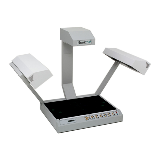
3 Device Overview Picture 1: Front side view For a first look at the BOOKEYE Color, some of the more important components have been identified in the photos here. These components are referenced in the operation manual. Picture 2: Details on the back side Note: Picture 1 and Picture 2 show device version R2. -
Page 15: Content On Delivery
The network cable connects the BOOKEYE Color scanner to the network. All parameters which define the BOOKEYE Color in the network must be set prior to the first use. The power cable connects the BOOKEYE Color to the wall outlet. -
Page 16: Establishing Connections
The wall outlet is equipped with a correctly dimensioned fuse. Turn the device off before plugging or unplugging any cable. Connect the wall outlet and the power supply connector at the BOOKEYE Color with the power cable. Picture 3: Connectors on backside... -
Page 17: Connecting A Foot Pedal Switch
Possible Disturbance at Power Up After connecting the BOOKEYE Color to the mains voltage and turning the main power switch on, the lamps should light up for a short moment. This is a design-related behavior of the lamps electronic ballast. -
Page 18: Operation
6 Operation Starting the BOOKEYE Color Press the START button. After the BOOKEYE Color is turned on, the lamps light up and the internal self test sequence starts. While the self test sequence runs, the display shows alternating in two lines:... -
Page 19: Switching Off The Bookeye Color
After switching off using the main switch, more time is necessary for the subsequent system start since all system parameters have to be restored. If the BOOKEYE Color is installed in a network with a high number of users, it might react with a delay on commands from the user interface. -
Page 20: Keyboard
The selected setting is displayed by LEDs at each function field. The START button and the STOP button control several functions. The function of these buttons is defined by the mode of operation of the BOOKEYE Color. The BOOKEYE Color has two modes of operation. -
Page 21: Format
Table 1: Size of the scanned area The “AUTO” setting activates the automatic size detection. By using the “AUTO” setting, the BOOKEYE Color scans the complete, maximum scan area. The size of the document which is placed on the document bed is recognized automatically and displayed in the correct size. -
Page 22: Type
TYPE Picture 8: Function field TYPE The function field TYPE defines the document type. At the end of the system-test the field lights up. Function Document type FLAT Documents with consistent thickness, e.g. single pages. Documents without binding or center fold. BOOK Documents with a high center fold, e.g. -
Page 23: Book
Picture 10: Example for document height Picture 11: Distance to document bed edge If these criteria are not met, the BOOKEYE Color produces an uncorrected image. Operation Manual Page 23... -
Page 24: Folder
7.2.3 FOLDER The type FOLDER is suitable for documents with plain differences in levels between left and right page. These are e.g. extensive files or documents without bound or center fold. Picture 12: Example for document used with FOLDER In combination with the setting PAGES BOTH, the left and right half of the document are focused and sent separately. -
Page 25: Pages
PAGES Picture 13: Function field PAGES The function field PAGES defines the output mode. At the end of the system-test the field lights up. The settings LEFT, RIGHT and BOTH activate the page separation. Function Output mode SINGLE No page separation. Selected document size as one image. LEFT Page separation activated. - Page 26 Examples: Scan area (white area) Selected setting Example 1: Function field FORMAT: A4. Function field PAGES: SINGLE. Example 2: Function field FORMAT: A3. Function field PAGES: LEFT Example 3: Function field FORMAT: A3 Function field PAGES: RIGHT Page 26 Operation Manual...
-
Page 27: Color
COLOR Picture 14: Function field COLOR The function field COLOR defines the color mode. At the end of the system-test the field lights up. Function Output mode COLOR Scans the document in 24-bit color mode. GRAY Scans the document in 8-bit gray scale mode. PHOTO Scans the document in bi-tonal (black/white) mode combined with a dithering effect. -
Page 28: Contrast
CONTRAST Picture 16: Function field CONTRAST The function field CONTRAST sets the contrast value while scanning. At the end of the system-test the field lights up. Moving the LED bar upwards increases the contrast value. Moving the LED bar downwards decreases the contrast value. COPIES Picture 17: Function field COPIES This function field is only active in the copier version of the device. -
Page 29: Set-Up Mode
After the self-test is completed, the LEDs light up in the same position which was active when the device was switched off. The display now shows the serial number of the BOOKEYE Color in two lines. Checking the current settings To check the current settings of the IP address, the subnet mask, the gateway address and DHCP value, perform the following steps. -
Page 30: Setting New Values
Setting new values To set new values for the displayed parameters, use the following buttons: — Use the up / down buttons at the function field TYPE to change the value for AAA as well as to switch the setting for DHCP between YES and NO. —... -
Page 31: The Integrated User Interface
9 The Integrated User Interface Start your browser. Enter the IP address of the scanner. The start screen of the integrated user interface opens. Picture 18: Start screen Click the button “Start Scan Application”. Operation Manual Page 31... -
Page 32: Picture 19: User Interface Main Window
The main window of the integrated user interface opens. Picture 19: User interface main window The main window is structured into three parts. The part on the right side shows a menu bar with four menu items: Options Paper Camera Settings The part on the left shows the buttons for preview scan and main scan. -
Page 33: Options
Options Picture 20: Select options Picture 20 shows all selectable options. The option “Book Fold Correction” must be installed to make it visible below the item Document Processing. Operation Manual Page 33... -
Page 34: Document Processing
9.1.1 Document Processing Book Fold Correction: This function corrects and flattens the hump at the book binding by using a mathematical algorithm. Example: Picture 21: Without “Book Fold Correction” Picture 22: “Book Fold Correction” activated For a proper function of the Book Fold Correction place the document to be scanned in the middle of the document bed. -
Page 35: Scan Mode
9.1.2 Scan Mode Sets the scan speed. High Quality reduces the scan speed to the half and improves the image quality. 9.1.3 Image Processing Rotates the image clockwise. Available are rotation angles of 0, 90, 180 and 270 degrees. 9.1.4 Image Defines the file format in which the scanned images are stored. -
Page 36: Picture 25: Jpeg Quality In Percent
JPEG Picture 25: JPEG quality in percent Quality: Defines the quality of the image in percent. TIFF Picture 26: Selection of TIFF compression Compression: Defines the type of compressions used for the images. Page 36 Operation Manual... -
Page 37: Picture 27: Data Format Pnm
Picture 27: Data format PNM Raw data of the scanned image. No options available for this data format. Please note that for all changes the following is valid: A new setting or a new value is immediately transferred to the scanner. Operation Manual Page 37... -
Page 38: Preview
9.1.5 Preview Picture 28: Preview Scaling Ratio Scales the size of the preview image. 9.1.6 Embed ICC Profiles Select Yes to embed ICC profiles to the images. ICC profiles are used to set color values for output devices, e.g. printer or plotter. Please note that for all changes the following is valid: A new setting or a new value is immediately transferred to the scanner. -
Page 39: Paper, Predefined Formats
Paper, Predefined Formats Picture 29: Predefined Formats 9.2.1 Format Auto: The size of the document to be scanned is recognized automatically. The document can be placed on any position in the maximum scan area (depending on the selected resolution). The surrounding border will be cropped automatically. -
Page 40: Switching Between Portrait / Landscape Format
9.2.2 Switching between Portrait / Landscape Format Portrait / Landscape: Select between portrait and landscape format. The portrait format is not always available, depending on the selected size of the scan area. An invalid combination of scan area size and portrait format returns the setting to the last valid setting or an error message is displayed. -
Page 41: Additional Margin [Pixel]
9.2.4 Additional Margin [Pixel] A positive value adds a margin in vertical and horizontal direction to the scanned image. A negative value reduces the image in vertical and horizontal direction by the selected size. Click on the slider to set the desired value. 9.2.5 Background Density [Binary] Controls the sensitivity of the automatic document size... -
Page 42: Paper, User Defined Formats
Paper, User defined Formats The size of the user defined formats can be selected in two ways. 1. Numeric Input: If no JAVA Plug-In is installed the size and the position of the scan area can be defined by numeric values. 2. -
Page 43: Picture 32: Unit Of Measurement List
9.3.1.1 Unit Picture 32: Unit of measurement list Select the unit of measurement in which the value shall be displayed. The maximum value of the selected unit of measurement are displayed in the fields “Maximum”. To define the size and the position of the scanned area, enter a value in the fields —... -
Page 44: User Defined Formats, Use Java Udf
9.3.2 User defined Formats, Use Java UDF At first select “Use Java UDF” at the menu item “Settings” (refer to chapter 9.5.4). At next click at “User defined Formats”. Picture 33: Preview Scan After a short moment the preview scan is displayed. The preview scan shows the complete scan area with the document. -
Page 45: Picture 34: Frame For User Defined Format
Select the scan area. To select the scan area, click into the preview scan with the mouse, hold the left mouse button pressed and raise up a frame with the desired size. Picture 34: Frame for user defined format After defining the scan area click the “Scan Preview Now” button or the “Scan Now” button to start the scan sequence. -
Page 46: Camera
Camera Picture 36: Select camera settings Depending on the selected mode, the parameters which can be changed will vary. If a parameter can not be changed, the sliders or buttons which belong to this parameter will not be displayed. Please note that for all changes the following is valid: A new setting or a new value is immediately transferred to the scanner. -
Page 47: Exposure Controls
9.4.1 Exposure Controls Picture 37: Color modes The camera offers four different color modes. Available modes are: True Color: True Color mode with 24 bit color depth. Grayscale: 8 bit grayscale mode. Line Art: 1 bit black/white (bitonal) mode. Photo: 1 bit black/white (bitonal) mode with dithering. -
Page 48: Use Cms
9.4.1.1 Modes “Line Art” and “Photo” Picture 38: Parameters for Line Art mode In the modes “Line Art” and “Photo” the “Gamma” value can not be set. For this reason the slider “Gamma” as well as the “Preselection” checkboxes are not visible. The automatic threshold function (Auto Threshold) can be selected in both modes. -
Page 49: Resolution
9.4.3 Resolution Picture 39: Available resolutions At this time 300 dpi resolution is available. As an option 400 dpi and 600 dpi will be available at a later time. 9.4.4 Brightness Sets the brightness level of the scanned image. Use the slider to change the brightness value or enter a numeric value into the field beside the slider. -
Page 50: Exposure
9.4.6 Exposure Picture 40: Exposure and Gamma settings Value range from 0 (zero) to 100. Sets the threshold value for the black cut function or for the auto exposure function. Function disabled. Black Cut Sets the threshold for black. All pixel values found in the image below the selected value are set to black. -
Page 51: Settings
Settings Picture 41: Settings 9.5.1 Language Selector Selects the language of the user interface. Available languages are “english”, “deutsch” and “russian”. If “russian” is selected, all text are displayed in Cyrillic fonts. The user interface shows all text in the selected language. Please note that for all changes the following is valid: A new setting or a new value is immediately transferred to the scanner. -
Page 52: Skin Selector
9.5.2 Skin Selector Offers different surfaces (skins) for the user interface. The currently available surfaces are “classic”, “classic-green” and “metal”. More skins can be designed and integrated by the user. 9.5.3 Show Status Window Picture 42: Scan status Activates an additional window which shows the current status of the scanner. 9.5.4 Use Java UDF Click the “Yes”... -
Page 53: Color Gain
9.5.5 Color Gain Only available in “True Color” mode. Picture 43: Color Gain „Red“ Sets the amplification separately for the red, green and blue color channel. The amplification can be set in a range from “–7” to “+7”. Operation Manual Page 53... -
Page 54: Control Buttons For Output Mode
Control Buttons for Output Mode Picture 44: Control buttons for output mode 9.6.1 Save Saves the scanned image. The default file name contains date and time as well as a continuous numbering. Example: Scan-2003-04-22_14-56-24.jpg After scanning the document, a window opens in which the directory and the file name can be entered. -
Page 55: Show
9.6.2 Show Opens a new browser window and shows the scanned image. Picture 46: Scanned image with function field bar Below the image a function field bar is displayed. Use these function fields to — save the image (refer to chapter 9.6.1), —... -
Page 56: Print
9.6.3 Print Prints the scanned image on the system printer. A window opens where the desired printer can be selected. Picture 47: Selecting the printer 9.6.4 Copy Copies the scanned image to a remote printer located in the network. The printer must be identified by its IP address. -
Page 57: Ftp Upload
9.6.5 FTP Upload Sends a scanned image to an FTP address. To enter the FTP address click on “Option” below the “FTP Upload” button. Picture 49: Definition of FTP address Click on the button “Apply” in order to transfer and save the change. 9.6.6 Mail Sends a scanned image via e-mail. -
Page 58: Turning Off The Device
Turning off the device Click the control button “STOP” to switch off the device. A window with a security query opens. Click the “Shutdown” button. Picture 51: Security query after shutdown command After confirming the query the lamps switch off and the display shows the message: System Shutdown **************** After the device is switched off, the browser window shows the final message. -
Page 59: Scanning
10 Scanning Select the output settings by clicking one of the buttons for output mode. If necessary set the options for the desired mode. Set all desired settings for the scan sequence as described in chapters 9.1 to 9.5.5. It is recommended to select the paper format AUTO from Paper, Predefined Formats. If the option Book Fold Correction is not installed, place the document at the document bed edge. -
Page 60: Scan2Net Firmware Update Procedure
11 Scan2Net Firmware Update Procedure 11.1 Basic requirements A basic requirement for a successful firmware update is to configure the browser as follows: • Set your browser to direct access to internet or if you are connected via a proxy: •... -
Page 61: Browser Settings For
12 Browser settings for … 12.1 … Netscape 6 Please note: Pictures show German version of the browser. Start your browser and select the menu item as displayed in the picture below. The arrow in the screenshots points on the item which has to be selected. Operation Manual Page 61... - Page 62 The marked menu item, shown in the picture above, forces the browser to reload the page content each time when it is selected. Page 62 Operation Manual...
-
Page 63: Internet Explorer 6
12.2 … Internet Explorer 6 Please note: Pictures show German version of the browser. Start your browser and select the menu item as displayed in the picture below. The arrow points on the item which has to be selected. The marked menu item, shown in the picture beside, forces the browser to reload the page content each time when it is selected. -
Page 64: Updating The Firmware
13 Updating the Firmware Execute the items of the following list to update the device's firmware. 1. Start your internet browser and enter the Image Access homepage address: http://www.imageaccess.de 2. On the left side in the section Support click on Downloads. -
Page 65: Scan2Net Firmware Setup Procedure
14 Scan2Net Firmware Setup Procedure Valid with Firmware V3.xx or higher. After a firmware update, the four menu items described in the following should be performed before starting to scan. The menu items for the setup procedure are accessible in the login level “Poweruser”. 14.1 How to enter the “Poweruser”... -
Page 66: Doing The Adjustments
14.2 Doing the Adjustments 1. Find the section “Adjustment & Support”. 2. Press the button “Adjustments”. Picture 54: „Poweruser“ information menu 3. Start in section “Focus & X/Y Adjustments”. Select the buttons from left to right and follow the steps which are displayed. Picture 55: Menu in section „Adjustment &... -
Page 67: Auto Focus
14.2.1 Auto Focus This function automatically finds the focus point for the highest sharpness and best image quality. 1. Press the "Auto Focus" button. 2. Place the “Line Reference Sheet S2N LRS-200”, which comes with the scanner, or a highly detailed document (small, fine print) on the scanner as shown on the screen. 3. -
Page 68: Y-Adjust
14.2.3 Y-Adjust This function adjusts the vertical start position accordingly to the documents bed edge. 1. Press the "Y-Adjust" button. 2. Remove all documents from the scanner's glass plate. 3. Press the "Next Step" button. 4. After the “Y-Adjust” function is finished the results will be displayed. 5. -
Page 69: Leaving The Adjustment Menu
14.2.5 Leaving the Adjustment Menu Click the S2N Scan2Net logo on top of the screen to return to the “Setup Device” screen (Picture 53). Click the “Scan Application” button to start scanning. Notice: Generally, there is NO reason to open the S2N Scan2Net scanner and work on the hardware. -
Page 70: Technical Data
15 Technical Data 15.1 Electrical Specifications Voltage : 230–240 V AC (US-Version: 110–120V AC) Frequency: 50 Hz (US-Version: 60 Hz) Power Consumption: Version N2 5 W (stand-by off) 250 W (stand-by operational) 280 W (operating) Version R2 / Version R1: 5 W (stand-by off) 300 W (stand-by operational) max. -
Page 71: Dimensions And Weight
15.3 Environmental Conditions Temperature Range: +5 to +40° C Relative Humidity: 20 to 80% (not condensing) Noise: 45 dB(A) 15.4 Dimensions and Weight Version N2: Dimensions: 880 x 685 x 673 mm (H x W x D) Weight: 28,5 kg Weight, ready for shipping: 43,5 kg Dimensions of the box: 1080 x 800 x 780 mm (H x W x D) -
Page 72: Ec Declaration Of Conformity
EC Declaration Of Conformity The undersigned, representing the manufacturer Image Access Computer GmbH Hatzfelder Strasse 161-163 42281 Wuppertal, Germany herewith declares that the Product: Bookeye Scanner Model designation: BE2-AAA-BCd with AAA = SCL or SGS or CGS B = R or N...
Need help?
Do you have a question about the BOOKEYE Color and is the answer not in the manual?
Questions and answers