Image Access Bookeye 4 Operation Manual
Hide thumbs
Also See for Bookeye 4:
- Setup manual (149 pages) ,
- Operation manual (53 pages) ,
- Installation manual (34 pages)
Table of Contents
Advertisement
Quick Links
Download this manual
See also:
Setup Manual
Advertisement
Table of Contents

Related Manuals for Image Access Bookeye 4


Summary of Contents for Image Access Bookeye 4
- Page 1 Operation Manual...
-
Page 2: Table Of Content, Part
File: BE4-V1A_OperationManual_B5.docx... -
Page 3: Table Of Content, Part
Image Access. All other trademarks are the property of their respective owners. Image Access reserves the right to change the described products, the specifications or documents at any time without prior notice. For the most recent version, always check our web site www.imageaccess.de... -
Page 4: Introduction
Dear Customer We congratulate you on the acquisition of this innovative product from Image Access. At Image Access, we are proud of the work we do; our products are the result of our extremely high production standards and stringent quality control. -
Page 5: About This Manual
About this Manual Operation Manual The Operation Manual provides all necessary information pertaining to the normal operation and behavior of the device. It is written for people who only operate the device and do not perform setup and adjustment procedures. All device elements and software functions are described in detail, although some of them might never be used. -
Page 6: Version History
Version History Version Published in Content/Changes/Supplements March 2013 Preliminary version for Bookeye 4-V1A Professional. July 2013 Preliminary version. Additional information about the glass plate operation modes. August 2013 First version. November 2013 Section C: Content change because of introduction of the new user interface ScanWizard. -
Page 7: Table Of Contents
F-A.4 Raccordement à l'alimentation électrique ..........29 Starting the Bookeye ® A.9.1 Switching the Bookeye ® 4 to Standby Mode A.9.2 F-A.4.1 Mise en marche du Bookeye 4 F-A.4.2 Commutation du Bookeye 4 sur le mode de veille Operation Manual Page 7... - Page 8 Table of Content, part 2 A.10 Book Cradles ................... 32 A.11 Glass Plate Functionality ................. 33 A.11.1 In General A.11.2 Glass Plate Positions A.11.2.1 Transport lock position A.11.2.2 Fully up position A.11.2.3 The 45 degree angled position A.12 Operating the motorized book cradle ............36 A.12.1 The Cradle Lock Button A.12.2...
- Page 9 Table of Content, part 3 B Touchscreen Operation --------------------------------------------------- 58 Select Application Screen ................. 58 Start Screen of the Kiosk User Interface ........... 59 B.2.1 Control Fields of the Touchscreen Touchscreen – Document Source ............61 B.3.1 Document Mode B.3.1.1 Auto Mode B.3.1.1.1 Document Position / Minimum Document Size...
- Page 10 Table of Content, part 4 Touchscreen – Viewer & Job Control ............82 B.5.1 Zonal OCR B.5.2 Job Mode B.5.2.1 Navigating through the list of images B.5.2.2 Moving an image to another position B.5.2.3 Adding an image at an any position to the list B.5.2.4 Deleting an image from the list B.5.2.5...
- Page 11 Table of Content, part 5 D The Setup Level ------------------------------------------------------------- 104 Access Level User .................. 105 D.1.1 Device Info D.1.2 Operation Info D.1.3 User Settings D.1.3.1 Language Selector D.1.3.2 Power Saving D.1.3.3 Volume D.1.3.4 Foot Pedal D.1.3.5 Glass Plate D.1.3.6 Splitting Start Page E Technical Data --------------------------------------------------------------- 116 Scanner Specifications ................
- Page 12 Table of Pictures Picture 1: Minimum distance between Bookeye and walls ..........21 Picture 2: Elements of the Bookeye 4-V1A ..............24 Picture 3: Connectors on the rear side ................25 Picture 4: Keyboard with Power button ................30 Picture 5: Book cradles in flat mode and closed .............. 32 Picture 6: Book cradles in V mode and closed ..............
- Page 13 Table of Pictures, part 2 Picture 36: Document placed correctly ................63 Picture 37: Document placed incorrectly ................63 Picture 38: List of Resolutions ..................65 Picture 39: Selector for Format settings ................66 Picture 40: Parameters for Maximum format ..............67 Picture 41: Book Mode Formats ..................68 Picture 42: Crop and Deskew screen ................70 Picture 43: Format DIN (=ISO) selected ................71 Picture 44: List of ANSI formats ..................72...
- Page 14 Table of Pictures, part 3 Picture 71: OCR result..................... 86 Picture 72: Bottom line with status ................... 87 Picture 73: TFT flat screen after selecting “Job mode”............. 87 Picture 74: Disclaimer when staring the Job mode ............88 Picture 75: Job mode start screen ................... 88 Picture 76: Controller circles blanked out ................
- Page 15 Operation Manual Page 15...
-
Page 16: A Hardware
Hardware Safety Notes Read and ensure that you understand the safety notes. The safety notes have been written to ensure your protection and for your safety. Follow all safety notes to avoid damage to the device. A.1.1 Marking of Safety Notes All safety notes are marked with a warning sign. -
Page 17: F-A.1 Notes De Sécurité
F-A.1 Notes de sécurité Lisez ces notes de sécurité et veillez à bien les comprendre. Ces notes ont été rédigées pour assurer votre protection et votre sécurité. Respectez toutes les notes de sécurité pour éviter d’endommager le dispositif. F-A.1.1 Marquage des notes de sécurité Toutes les notes de sécurité... -
Page 18: Safety Precautions
Image Access Technical Support. The scanner should be used only with the power supply that is delivered with the scanner. If you are unsure, please contact the Image Access Technical Support. 10. Image Access recommends plugging the scanner into an appropriately-rated power conditioner. -
Page 19: F-A.2 Précautions De Sécurité
En cas de doute, veuillez contacter l’Assistance Technique de Image Access. 10. Image Access recommande de brancher le scanner sur un climatiseur électrique d’une puissance appropriée. 11. Coupez toujours l’alimentation électrique et débranchez le cordon d’alimentation de la prise de courant murale avant de nettoyer le scanner. -
Page 20: Certification
Certification Bookeye ® 4 scanner: All safety requirements of the following standards are fulfilled by the IEC 60950-1, International Safety Standard for Information Technology Equipment UL 60950-1, Safety for Information Technology Equipment (US standard) CAN/CSA C22.2 No.60950-1, Safety for Information Technology Equipment (Standard of Canada) EN 60950-1, Safety for Information Technology Equipment (European standard) All approval marks of the above named tests can be found on the type label of the device. -
Page 21: Device Location
Device Location A.4.1 Environment Choose a location that complies with the temperature and humidity specifications. For detailed information on these specifications, see the chapter E.4. Please allow • a minimum distance of 500 mm (20 inch) from any side walls, •... -
Page 22: Ambient Light
A.4.2 Ambient Light Bookeye ® 4 location should have a controlled ambient light situation. The light scenarios should avoid direct sunlight or spot light from light beams. Also light sources that cause sharp shadows on the document on the book cradles or high levels of ambient light could influence the scan result negative. -
Page 23: Content On Delivery
Content on Delivery The scanner is delivered in a wooden transport box. The transport box also contains • A folder with four CSTT-2 reference targets • Three White Reference targets BE4-WA-V1-A • A foot pedal switch (optional) • Patch cable, length 3 meters. •... -
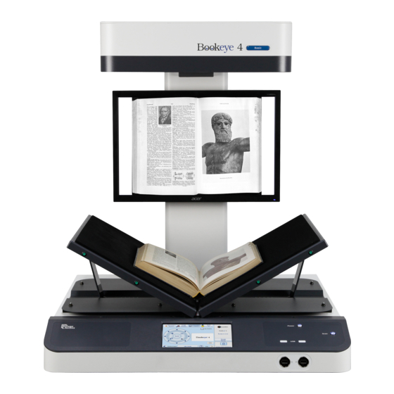
Page 24: Device Overview
Device Overview Picture 2: Elements of the Bookeye 4-V1A Bookeye 4 scanner have been identified in the ® Some of the major components of the above picture. These components are referenced in this operation manual. Bookeye ® 4 scanner main hardware elements are: 7 inch WVGA touchscreen: The touchscreen shows all menus and provides access to all functions directly from the scanner. -
Page 25: Connectors On The Rear Side
A.8.1 Connectors on the Rear Side For easy orientation, the connectors found on the rear side of the scanner are depicted in the following picture and described below. Picture 3: Connectors on the rear side Connector for Recovery key. Bookeye ®... -
Page 26: F-A.3 Aperçu Du Dispositif
F-A.3 Aperçu du dispositif Photo 1: Eléments du Bookeye 4 Bookeye 4 ont été identifiés sur la photo ® Certains des éléments essentiels du scanner ci-dessus. Ces éléments sont des références dans ce manuel d’utilisation. 1. Ecran tactile : L’écran tactile affiche tous les menus utilisés pour paramétrer et Bookeye ®... -
Page 27: F-A.3.1 Connecteurs Sur Le Côté Arrière
F-A.3.1 Connecteurs sur le côté arrière Pour faciliter l’orientation, les connecteurs du côté arrière du scanner sont illustrés sur la photo ci-après et décrits ci-dessous. Photo 2: Connecteurs sur le côté arrière Port série / connecteur de la clé de récupération. Interrupteur électrique principal. -
Page 28: Connecting The Power Source
Connecting the Power Source Before connecting the scanner to the external power supply and the power supply to the electrical outlet, check the following items: Ensure the electrical outlet is in perfect condition and that it is properly grounded. Ensure that the electrical outlet is equipped with a fuse with the proper capacity. -
Page 29: F-A.4 Raccordement À L'alimentation Électrique
F-A.4 Raccordement à l'alimentation électrique Avant de raccorder le scanner à l’alimentation électrique extérieure, et donc à la prise de courant, vérifiez les points suivants: Veillez à ce que la prise de courant soit en parfait état et qu’elle est correctement mise à... -
Page 30: Switching The Bookeye ® 4 To Standby Mode
Bookeye ® A.9.1 Starting the Push the illuminated “Power” button to start the scanner. Power button Picture 4: Keyboard with Power button The button illumination changes to blue. The scanner starts with self-test routines and verifies all system components. Status messages will be displayed on the TFT flat screen and on the WVGA color touchscreen. -
Page 31: Commutation Du Bookeye 4 Sur Le Mode De Veille
Bookeye ® F-A.4.1 Mise en marche du Appuyez sur le bouton "Power" pour éteindre le scanner sous tension. Bouton Power Photo 3: Clavier avec le bouton "Power" La lumière de ce bouton devient bleue. Le scanner démarre par des procédures d’auto-test et vérifie tous les composants du système. -
Page 32: Book Cradles
A.10 Book Cradles Bookeye ® 4 V1A scanner has a motorized book cradle which can be operated in two modes. Either in flat position … Picture 5: Book cradles in flat mode and closed … or in V position. Picture 6: Book cradles in V mode and closed The V position is recommended for very delicate, old documents. -
Page 33: Glass Plate Functionality
A.11 Glass Plate Functionality A.11.1 In General Note: For security reasons, the opening force of the glass plate is limited. A.11.2 Glass Plate Positions The glass plate has three positions. A.11.2.1 Transport lock position When the scanner is delivered, the glass plate is fixed in its fully up position by two transport locks (two rubber bumpers). -
Page 34: A.11.2.2 Fully Up Position
A.11.2.2 Fully up position Picture 9: Glass plate completely opened At the bottom side of the camera neck are four rubber bumpers located. The rubber bumpers in front are the transport locks (see chapter A.11.2.1). The two rubber bumpers in the back protect the TFT flat screen and limit the movement of the glass plate. -
Page 35: A.11.2.3 The 45 Degree Angled Position
A.11.2.3 The 45 degree angled position The glass plate can be stopped by the operator in the 45 degree position. When stopped, the glass plate will be hold in this position. This is a stable position and the recommended working position when scanning with the glass plate. -
Page 36: Operating The Motorized Book Cradle
A.12 Operating the motorized book cradle A.12.1 The Cradle Lock Button Off: If the button light is off, the magnetic lock function is turned off Blue: If the button light is blue, the magnetic lock function of the glass plate is activated. Red: If the button light is red, the magnetic lock is engaged and the glass plate is held in the closed position. -
Page 37: Glass Plate Operating Modes
A.13 Glass Plate Operating Modes Bookeye ® 4 scanner has two operation modes for the glass plate: • Manual mode • Automatic mode. A.13.1 Setting the Operation Modes The scanner starts with the operation mode which was set before it was powered-down. To toggle between the modes, press and hold the Cradle Lock button (Picture 11) until the Cradle Up and Cradle Down buttons blink. -
Page 38: Manual Mode
A.13.2 Manual Mode Bookeye ® 4 scanner in manual mode, the Cradle Lock button While working with the only signalizes if the magnetic lock is activated (blue) or not (not illuminated). The glass plate will be hold in closed position until •... -
Page 39: Working With The Book Cradle Plates
A.13.4 Working with the Book Cradle Plates The book cradles can be moved up and down by using the Cradle Up and Cradle Down buttons. Place the document, e.g. a book, on the cradle plates and open the cradle plates until the book spine can freely move between the book cradle plates. -
Page 40: Picture 17: Lowering The Book Cradle
Push the book cradle down manually until both sides of the document are at the same height. Picture 18: Lowering the book cradle Activate the magnetic lock of the glass plate by pressing the Cradle Lock button. The button is illuminated in blue Move down the glass plate until the cradle lock engages. -
Page 41: Picture 18: Glass Plate Closed
If necessary, move the cradle plates up or down in small steps with the control buttons to optimize the document’s position below the glass plate. Picture 19: Glass plate closed The cradle lock has a limited force for security reasons. After successfully adjusting the book cradle height and the appropriate pressure, the cradles support the weight of the book. -
Page 42: A.14 The "Finger Removal" Function
Please note: The following pictures show an earlier version of the Bookeye 4-V2 scanner housing. Picture 20: Book at book cradle in flat position Picture 21: Book at book cradle opened in “V” position •... -
Page 43: Finger Positions
A.14.2 Finger Positions Another important criterion for a proper function of the “Finger Removal” function is the position of the fingers which hold the book in a flat position. • The fingers must be positioned in a vertical area of max 1 inch = 25 mm width measured from the book fan at each side of the book. -
Page 44: Wrong Finger Positions
A.14.3 Wrong Finger Positions Some finger positions can cause malfunction of the “Finger Removal” function. The following chapters show a few examples of wrong and correct finger positions. A.14.3.1 Distance too small The fingers should be positioned with distance to the text or to graphical elements in the document. -
Page 45: A.14.3.3 Fingers Hold Too Close To The Margin Of The Document
A.14.3.3 Fingers hold too close to the margin of the document When the fingers are hold too close to the document’s margin, they will not be removed by the “Finger Removal” function. Wrong Correct Move the fingers in small steps from the edge of the document to the inside and repeat the scan sequence. -
Page 46: Examples Of Finger Removal
A.14.4 Examples of Finger Removal Some examples in the following chapter show the functionality of the “Finger Removal” function. A requirement is that in the ScanWizard user interface or in the kiosk application (see chapter B.3.1 and B.3.1.2) the scanner is set to Book Mode. A.14.4.1 Book positioned at the book cradle Book Mode, Finger Removal Mode: Book Fan Book position... - Page 47 Book Mode, Finger Removal Mode: On, Finger Removal Color: Black Note: The Finger Removal Color is defined in the ScanWizard user interface. Book and finger position Scan result The resulting image now shows the area where the finger contour was detected. The detected area is filled with massive black color.
- Page 48 Large book (e.g. catalogue) kept flat by single finger Book Mode, Finger Removal Mode: On, Finger Removal Color: Auto Note: The Finger Removal Color is defined in the ScanWizard user interface. Book and finger position Scan result The book fan has been removed and the surrounding black area is reduced to a minimum. The scan result shows in the lower left corner a part of the finger.
-
Page 49: A.14.4.3 Multiple Fingers Hold The Book
A.14.4.3 Multiple fingers hold the book Book Mode, Finger Removal Mode: Book Fan Book and multiple fingers position Scan result Small book kept flat by multiple fingers Book Mode, Finger Removal Mode: On, Finger Removal Color: Auto Note: The Finger Removal Color is defined in the ScanWizard user interface. If parts of the content of the book are covered by a finger or by multiple fingers, the removal function detects the contour and fills the area with the selected fill option. - Page 50 Book Mode, Finger Removal Mode: On, Finger Removal Color: Auto Note: The Finger Removal Color is defined in the ScanWizard user interface. Book and multiple fingers position Scan result The position of the three fingers has been detected. The fingers contour is eliminated in the resulting image and filled with a pattern and/or color.
-
Page 51: A.14.4.4 Small Books With Pattern At Margin
A.14.4.4 Small books with pattern at margin If a book has small dimensions, the finger removal mode Book Fan very often delivers good results without flattening the book by fingers. Book Mode, Finger Removal Mode: Book Fan Book position Scan result The scan result shows the content of both pages. -
Page 52: The "Splitting" Function
Picture 23 shows as an example how single pages can be positioned at the book cradle plates. Please note: The following pictures show a former version of the Bookeye 4-V2 scanner. Picture 24: Single pages on book cradle plates In general: The sheets should have a distance of at least 25 mm (1 inch) to the gap between the book cradle plates. -
Page 53: Splitting" Function With A Single Document
A.15.2 “Splitting” function with a single document Select the settings as described in chapter A.15.1 Picture 25: Single document on book cradle plate With a single document placed on a book cradle plate the scanner displays only the scanned image on the external monitor or in the browser window (S2N user interface). For the empty side of the book cradle the scanner shows the Bookeye screen saver screen. -
Page 54: Splitting" Function With Single Document At Middle Of The Book Cradle Plates
A.15.3 “Splitting” function with single document at middle of the book cradle plates Depending of the alignment of the document and of the selected Format mode, the results of the “Splitting” function differ. Format: Crop and Deskew Parameters set as follows: Document Mode: Auto Mode Format: Crop and Deskew Splitting Image: Auto... -
Page 55: Picture 27: Splitting Result With Format = Auto
Format: Auto Parameters set as follows: Document Mode: Auto Mode Format: Auto Splitting Image: Auto If the document is placed in the middle of the scan area the image is split along the detected middle of the document Picture 28: Splitting result with Format = Auto The resulting images show the parts of the document with a black border. -
Page 56: Splitting" Function With A Book
A.15.4 “Splitting” function with a book It is recommended to set the book cradle plates into “V” position when scanning books or other documents with a book spine. Picture 29: Book cradle plates set to “V” position The book cradle plates can be shifted horizontally from each other (see chapter 0). This is recommended for books with a large book spine. -
Page 57: Document Positions Which Can Result In Malfunction
A.15.5 Document positions which can result in malfunction A.15.5.1 Single pages Always place single pages on the book cradle which is in flat position. Position the single pages with at least a minimum distance of 25 mm (1 inch) between the pages. -
Page 58: B Touchscreen Operation
Touchscreen Operation Bookeye ® 4 scanner can be controlled in two ways. • Via the integrated touchscreen. The functions of the touchscreen are described starting with chapter B.2. • Via a standard browser and the ScanWizard user interface. A short description of the functions of the integrated ScanWizard user interface starts in chapter C.1. -
Page 59: Start Screen Of The Kiosk User Interface
Start Screen of the Kiosk User Interface After touching Scan2Net kiosk application starts with Viewer&Job Control screen. Picture 34: Viewer & Job Control screen The touchscreen is structured in four sections, which allow operators to control and select various functions of the scanner. This section shows the main controls or parameters depending on the selected control field in section 2. -
Page 60: Control Fields Of The Touchscreen
B.2.1 Control Fields of the Touchscreen By touching the buttons in section 2 each menu screen can be reached directly. The chapters B.3 to B.6 describe the functions of the menus in detail. Touch this button to start the scan sequence. Touch this button to return to the start screen from every other menu. -
Page 61: Touchscreen - Document Source
Touchscreen – Document Source The Document Source screen allows selecting from a wide range of scan parameters. Picture 35: Document Source screen The content of the menus which are selectable with the buttons can vary. This depends on the selected document mode. The variation affects specially the content of the Format menu. -
Page 62: Document Mode
B.3.1 Document Mode The Document Mode setting defines the focusing method when scanning documents. Picture 36: List of Document Modes B.3.1.1 Auto Mode This mode automatically detects the position of the book cradle and the type of document to be scanned. The focus is set depending on the detected document mode that matches the best. -
Page 63: Document Position / Minimum Document Size
B.3.1.1.1 Document Position / Minimum Document Size Please note: The following pictures show a former version of the Bookeye 4 scanner. Example for correct document position … …and image result Picture 37: Document placed correctly Image shows only the document Example for false document position …... -
Page 64: Book Mode
B.3.1.2 Book Mode Recommended method for scanning books. The book binding curvature will be compensated and flattened out. The focus will be set depending on the form of the book and its curvature. The focus will be set depending on the position of the book cradle plates. -
Page 65: Resolution
B.3.2 Resolution The Resolution setting allows selecting a resolution from a list of resolution values Bookeye ® 4 scanner. supported by the Picture 39: List of Resolutions Touch the blue arrow beside the currently selected value to open the list of available resolutions. -
Page 66: Format
B.3.3 Format The Format button allows defining the scan area size. The bottom line of the button Format shows the current format setting. Picture 40: Selector for Format settings Depending on the Document Mode selected, the available formats will vary. The table below shows the dependencies between Document Mode and Format. -
Page 67: Maximum
B.3.3.1 Maximum With Maximum three buttons will be displayed. Picture 41: Parameters for Maximum format Landscape Scans the maximum scan area in landscape orientation. Portrait left Scans the area left from the gap between the book cradle plates in portrait orientation. -
Page 68: Auto
B.3.3.2 Auto The complete scan area will be scanned. Picture 42: Book Mode Formats Auto The resulting image will be reduced to the document size. If the document is not aligned to the horizontal and vertical red laser lines the resulting images will have the smallest possible black margin. -
Page 69: Finger Removal Mode
B.3.3.2.1 Finger Removal Mode The Finger Removal Mode allows selecting from three settings. Disables the Finger Removal Mode. Book Fan The book fan at the left and right side will be detected and eliminate from the image. The book fan at the left and right side will be detected and eliminate from the image. -
Page 70: Crop And Deskew
B.3.3.3 Crop and Deskew The complete scan area will be scanned. Picture 43: Crop and Deskew screen If a document is not placed perfectly aligned horizontally and vertically, this function will correct the alignment. The resulting image shows the aligned document without any border. Example: Scanning with Format ... -
Page 71: Din
B.3.3.4 When selecting DIN, an additional small window is displayed in the touchscreen. It contains the available DIN (=ISO) paper sizes. Picture 44: Format DIN (=ISO) selected Depending on the selected paper size the buttons for Landscape, Portrait left and Portrait right are inactive (= gray) or active. -
Page 72: Ansi
B.3.3.5 ANSI When selecting ANSI, an additional small window is displayed in the touchscreen. It contains the available ANSI paper sizes. Picture 45: List of ANSI formats Depending on the selected paper size the buttons for Landscape, Portrait left and Portrait right are inactive (= gray) or active. -
Page 73: Splitting Image
B.3.4 Splitting Image The button Splitting Image is used to select splitting the document scanned for the output images. Picture 46: Splitting Image Left: The selected format will be scanned completely. Only the left half of the selected format will be displayed. Right: The selected format will be scanned completely. -
Page 74: Scan Mode
B.3.5 Scan Mode The Scan Mode screen allows the user to select from two possible scan modes. Picture 48: Available Scan Modes High Quality Scans with reduced scanning speed but improved scanning quality. Fast Scans with normal speed, depending on the selected scan resolution. In general, the scan speed depends at the selected resolution. -
Page 75: Exposure
B.3.6 Exposure The Exposure screen allows selecting the functions Black Cut and Auto. Fixed switches the function off. Picture 49: Exposure Modes When Black Cut or Auto is selected a numeric key pad opens. Picture 50: Numeric key pad to set threshold value Black Cut Sets the threshold for black. -
Page 76: Auto Density [Binary]
B.3.7 Auto Density [Binary] This parameter defines the scanner’s sensitivity for the automatic format detection. Default value: 40 Picture 51: Auto Density slider When scanning dark documents, the value should be reduced in small steps until the desired result is achieved. Please note: The higher the numeric value, the more contrast there must be between background and scanned document. -
Page 77: Touchscreen - Image Quality
Touchscreen – Image Quality The Image Quality screen allows setting a wide range of image quality parameters. Picture 52: Image Quality 1 In color mode Binary two additional menu items will be displayed. These are the menu items Invert and Despeckle. Picture 53: Image Quality 2 Operation Manual Page 77... -
Page 78: Color Mode
B.4.1 Color Mode By touching the selection arrow of the Color Mode section the list of available color modes opens. Picture 54: List of Color Modes Touch the title of the desired color mode to select the mode. The list closes subsequently. Picture 53 shows the available color modes. -
Page 79: Tiff
B.4.2.2 TIFF Picture 56: Submenu File Format TIFF With the TIFF file format, the compression method of the file can be selected with the TIFF Compression buttons. CCITT G4 Recommended with color mode “Binary”. JPEG Recommended for all other color modes. None Disables the data compression. -
Page 80: Brightness
B.4.3 Brightness Picture 57: Brightness slider The Brightness slider defines the resulting brightness in the image. Lower brightness values result in darker images, higher values result in brighter images. Values close to 0% or to 100% may result in unwanted artifacts. Move the slider indicator to the desired position to set the value. -
Page 81: Image Rotation
B.4.7 Image Rotation Picture 61: Image Rotation The value selected from the list defines the rotation of the image in a clockwise direction. The image will be rotated directly after scanning and before display B.4.8 Mirror Picture 62: Mirror This control mirrors the image along the selected mirror axis. Using this setting can be helpful if scanning transparencies from the back. -
Page 82: Touchscreen - Viewer & Job Control
Touchscreen – Viewer & Job Control The Viewer Control screen allows the operator to control and modify the image on the TFT flat screen. Picture 65: Viewer & Job Control screen The preview section (1) represents the TFT flat screen. The scanned image is displayed on the TFT flat screen and with reduced quality in the preview section right beside the controller elements. - Page 83 The controller is structured in three round elements (circles). The outer circle contains the keys to move the zoomed area across the image. The middle circle contains the keys to zoom in zoom out rotate the image in clockwise direction in steps of 90 degrees scale the image to the real size of the source document.
-
Page 84: Zonal Ocr
B.5.1 Zonal OCR Bookeye ® 4 offers a zonal OCR function. This function can be activated by the button positioned right below the preview section. Zonal OCR means, that only the marked area will be processed by the OCR function. Text and line feed will be found only. -
Page 85: Picture 68: Rectangle Defines The Area For Ocr Function
Touch the image at an arbitrary position. A red rectangle will be displayed. Picture 69: Rectangle defines the area for OCR function Exit: Press Exit to return to the former screen. CUT: Press the CUT button. The next screen will display the defined area more detailed. -
Page 86: Picture 70: Selected Area Magnified
Press CUT to separate the previously defined area from the complete image and to display it in detail. Picture 71: Selected area magnified The next screen shows the selected area magnified and allows again defining an area for the OCR process. Press OCR to start the OCR process. -
Page 87: Job Mode
B.5.2 Job Mode The bottom line of the Viewer & Job Control screen is different to the bottom line of the other screens. Picture 73: Bottom line with status The bottom line shows • the current scan mode status, • the button to switch the job mode between Single and Job mode •... -
Page 88: Picture 74: Disclaimer When Staring The Job Mode
Before scanning the touchscreen displays a disclaimer, which has to be accepted. Picture 75: Disclaimer when staring the Job mode After accepting the disclaimer, the Viewer&Job Control screen opens. It contains some additional control buttons above and below the preview section. Picture 76: Job mode start screen Page 88 Operation Manual... -
Page 89: Navigating Through The List Of Images
B.5.2.1 Navigating through the list of images The control buttons allow navigation through the list of scanned images and image handling while working in Job mode. The currently scanned image is always displayed in the preview section of the touchscreen and will be added as last image to the list displayed at the TFT flat screen. Function of the control buttons: Moves up- and/or downwards through the list of images to mark an image. -
Page 90: Moving An Image To Another Position
B.5.2.2 Moving an image to another position Use the upwards / downwards buttons to mark the image to be moved. Press this button to select the image. The image now can be moved with the upwards / downwards buttons to the new position. Press this button again to place the image at the new position. -
Page 91: Finalizing The Job Mode
B.5.2.6 Finalizing the Job mode Before finalizing the Job mode the scanned images can be transferred to different destinations. Picture 78: Destination to finalize Job mode The destinations are identical to the destinations described in chapter B.6 and its subchapters. Before the Job mode will be finalized, a message is displayed at the touchscreen. -
Page 92: Touchscreen - Send To
Touchscreen – Send To This menu provides the output options in order to transfer the scanned images to the desired destination. Picture 80: "Send To" screen #1 Due to the dimension of the touchscreen, not all output options can be displayed at the same time. -
Page 93: Changing A File Name Or Other Entries
B.6.1 Changing a file name or other entries In some of the option menus the file name can be changed. To change the file name, touch the respective line. The screen changes to an alphanumeric keyboard. Picture 82: Alphanumeric keyboard Use the arrow keys to position the cursor in the line. -
Page 94: Usb Options
B.6.2 USB Options Two USB connectors are available at the front of the scanner to connect suitable USB data carriers, for example USB sticks. Touching USB Options displays the directory of a connected USB data carrier. Picture 83: Directory of connected USB data carrier While the directory of the USB data carrier is displayed, the LED indicator of the respective connector is continuously illuminated. -
Page 95: Copy Options
B.6.3 Copy Options Touch Copy Options to switch to the screen with the preset copy option configurations. Three preset options can be stored and activated with the buttons Copy1 to Copy3. Picture 84: Parameters of Copy Options The parameters displayed in the above picture can only be changed from the Scan2Net® setup interface, user level Poweruser. -
Page 96: Ftp Options
B.6.4 FTP Options Touch FTP Options to switch to the screen with the preset FTP server configurations. Three preset FTP servers can be stored and activated with the buttons FTP 1 to FTP 3. Picture 86: Parameters of FTP Options From the touchscreen, only the entry for File Name can be changed. -
Page 97: Network Options
B.6.5 Network Options Touch Network Options to switch to the screen showing the preset network configurations. Three preset configurations can be stored and activated with the buttons Network 1 to Network 3. Picture 87: Parameters of Network Options From the touchscreen, only the entry for File Name can be changed. To change the entry, touch the respective line. -
Page 98: Mail Options
B.6.6 Mail Options Touch Mail Options to switch to the screen showing the preset email configurations. Three preset configurations can be stored and activated with the buttons Mail 1 to Mail 3. Picture 88: Parameters of Mail Options To change an entry, touch the respective line. From the touchscreen the values for •... -
Page 99: Transaction Modes
B.6.6.1 Transaction modes Two transaction modes are available for the mail transfer. The parameters for the transaction modes can be set from the Scan2Net® setup interface. The mode, selected in the Scan2Net® setup interface, influences the process when a scanned image should be mailed. Automatic When pressing the button Mail image via SMTP at the touchscreen, the image will be sent to the address defined in the screen Mail Options... -
Page 100: C The Scanwizard User Interface
The ScanWizard User Interface Essentially, the scanner is a web server and comes with its own HTML based user interface, named ScanWizard. A basic requirement before working with the integrated ScanWizard user interface is to configure the browser as follows: •... -
Page 101: The Scanwizard User Interface
The ScanWizard User Interface After pressing the Launch Scan Application button the browser will show the ScanWizard interface. Picture 91: ScanWizard interface You can bookmark the address of the ScanWizard interface in your browser for easy access later. ScanWizard is a function rich software which allows the user configuring and operating the scanner easily without any additional software. -
Page 102: Picture 92: Online Help
These tool bars are described in detail in the online help function included in the ScanWizard interface, in the “Administration” menu, item “Online Help”. Picture 93: Online Help To exit the ScanWizard interface click on the main menu item “Administration” and then click on “Exit”. -
Page 103: Information
Information Click on the button Information in the Scan2Net® main menu (Picture 89) to get a short summary of the device parameters. Picture 95: Information The screen is helpful if technical support is necessary. It shows e.g. the exact device type, the installed firmware version as well as currently installed options. -
Page 104: D The Setup Level
The Setup Level Please note: The screenshots in this chapter are taken from a WideTEK scanner. The Bookeye ® content of nearly all menus are identical with the menus of the scanner. Bookeye 4 scanner, a hint will be ® If a menu has a special content at the given. -
Page 105: Access Level User
Access Level User Click the button User . This will open the below displayed screen. Picture 97: User screen The user screen is divided into two sections. The section Device Information shows some details of the scanner and gives general operation information. -
Page 106: Device Info
D.1.1 Device Info In the section Device Information, click the button Device Info and the following list (Picture 97) will be displayed. Specific information can be reached by clicking the links below the headline Device Info. Picture 98: Device Info screen Bookeye ®... -
Page 107: Picture 98: Firmware Information
The most important information for users is the firmware version in the second table. Picture 99: Firmware information Other information may be of interest if a service technician is onsite or if the service hotline is called. To return to the USER screen (Picture 96) scroll down completely and click the Back to Main Menu button. -
Page 108: Operation Info
D.1.2 Operation Info In the section Device Information click the button Operation Info and the following list will show various scan counters and elapsed times. Picture 100: Operation Info screen The following table gives a brief description. Field Description Total Scan Count The total number of scans performed since the scanner left the factory. -
Page 109: User Settings
D.1.3 User Settings Please note: The screenshot in chapter D.1.3.5 shows the menu of a BE4-V1A scanner. All other screenshots are identical from content, but taken from another scanner model. In the section User Settings click the button User Settings and the following screen will be displayed. -
Page 110: Language Selector
D.1.3.1 Language Selector Use the function Language Selector to set the language for the user interface and the Bookeye 4 scanner. ® OCR language of the Picture 102: Language Selector screen Click on the selection arrow beside Language and a list of available languages opens. Select the desired language for the user interface with a mouse click. -
Page 111: Power Saving
D.1.3.2 Power Saving Use the function Power Saving to set the timers for the standby modes. Four settings can be defined. Click on the link Power Saving. Picture 103: Power Saving Click on the selection arrow to open the list of available values for the respective standby mode. -
Page 112: Volume
D.1.3.3 Volume Click the button Volume to set the loudspeakers volume of the scanner. Picture 104: Volume level A screen opens and shows a graphic to symbolize the volume. Click on the percentage value to change the volume level. The color of the graphic will change depending on the selected volume level. -
Page 113: Foot Pedal
D.1.3.4 Foot Pedal Click the button Foot Pedal to define a function for the foot pedals. Picture 105: Foot pedal settings The scanner has two connectors on its back to connect foot pedals. For each foot pedal a specific action can be defined. Click below the designated foot pedal and select from the drop-down list which action should be executed when the pedal is operated. -
Page 114: Glass Plate
D.1.3.5 Glass Plate Click the button Glass Plate to define the action of the scanner when the glass plate lock is engaged. Picture 106: Setting for automatic mode Start scan defines if the scanner starts scanning after the glass plate lock is engaged. Start scan? Yes: The scan sequence starts after the glass plate lock is engaged. -
Page 115: Splitting Start Page
D.1.3.6 Splitting Start Page Click the button Splitting Start Page and select either the left page or the right page as start page. Picture 107: Splitting start page In some cases it is necessary to start splitting the documents image in reverse order, i.e. starting with the right side followed by the left side in the second step. -
Page 116: E Technical Data
Technical Data Scanner Specifications Scan Area / Document Size Maximum scan area 635 x 850 mm (25 x 33.5 inch) Scanner resolution 400 x 400 dpi Optical resolution 400 dpi Pixel dimension 9.3 x 9.3 µm Minimum document size 100 x 100 mm / 4 x 4 inch Luminosity Light intensity while scanning: Max. -
Page 117: Electrical Specifications
Electrical Specifications External Power Supply Voltage 100 – 240 V AC Frequency 47 – 63 Hz Inrush current 120 A max / 264 V AC Efficiency 85 % ≤ 0.5 W Idle consumption Operating temperature 0 to 65 °C / 32 to 150 °F Operating humidity 20 …80 % RH, non-condensing ECO standard... -
Page 118: Dimensions And Weight
Dimensions and Weight Scanner outer dimensions, book cradle closed 1100 x 880 x 855 mm (H x W x D) 43.3 x 34.6 x 33.7 inch Scanner outer dimensions, book cradle opened 1100 x 1000 x 855 mm (H x W x D) 43.3 x 39.4 x 33.7 inch Total weight of scanner, ready to use Approx. -
Page 119: Ce Declaration Of Conformity
Image Access GmbH Hatzfelder Strasse 161 – 163 42281 Wuppertal, Germany herewith declares that the Product: Bookeye 4 V-Cradle Book Scanners Model Designation: BE4-xxxxx-yyy The x can be minimum 3 and maximum 5 alphanumeric characters representing the equipment feature. The y can be maximum 3 alphanumeric characters representing the scanner version. - Page 120 EMC: EMC Directive 2004/108/EC as per EN 55022 :2006 + A1 :2007 Class B EN 61000-3-2:2006 EN 61000-3-3:2008 EN 55024 :1998 + A1:2001 + A2:2003 Passed according criteria class A and B EN 61000-4-2:2009 EN 61000-4-3:2006 + A1 :2008 EN 61000-4-4:2004 EN 61000-4-5:2006 EN 61000-4-6:2009 EN 61000-4-11:2004...
-
Page 121: Fcc Declaration Of Conformity
Responsible party: Image Access GmbH Hatzfelder Strasse 161 – 163 42281 Wuppertal, Germany Product: Bookeye 4 V-Cradle Book Scanners Model Designation: BE4-xxxxx-yyy The x can be minimum 3 and maximum 5 alphanumeric characters representing the equipment feature. The y can be maximum 3 alphanumeric characters representing the scanner version. - Page 122 For your notes Page 122 Operation Manual...
Need help?
Do you have a question about the Bookeye 4 and is the answer not in the manual?
Questions and answers