Image Access Bookeye 4 Operation Manual
V1a professional series
Hide thumbs
Also See for Bookeye 4:
- Setup manual (149 pages) ,
- Operation manual (122 pages) ,
- Installation manual (34 pages)
Table of Contents
Advertisement
Quick Links
Advertisement
Table of Contents

Related Manuals for Image Access Bookeye 4


Summary of Contents for Image Access Bookeye 4
- Page 1 V1A-C35 Operation Manual...
- Page 2 File: ArbVers_BE4-V1A-C35_OperationManual_2015-KW45.docx Art.-Nr.: BE4-V1-C35-MAN-EN...
- Page 3 Image Access. All other trademarks are the property of their respective owners. Image Access reserves the right to change the described products, the specifications or documents at any time without prior notice. For the most recent version, always check our web site www.imageaccess.de...
-
Page 4: Introduction
Dear Customer We congratulate you on the acquisition of this innovative product from Image Access. At Image Access, we are proud of the work we do; our products are the result of our extremely high production standards and stringent quality control. -
Page 5: About This Manual
About this Manual Operation Manual The Operation Manual provides all necessary information pertaining to the normal operation and behavior of the device. It is written for people who only operate the device and do not perform setup and adjustment procedures. All device elements and software functions are described in detail, although some of them might never be used. -
Page 6: Version History
Version History Version Published in Content/Changes/Supplements January 2017 First version for Bookeye 4-V1A-C35 Rev. B Page 6 Operation Manual... -
Page 7: Table Of Contents
Table of Content Introduction -------------------------------------------------------------------------- 4 About this Manual ----------------------------------------------------------------- 5 Version History --------------------------------------------------------------------- 6 A Safety Notes and Device Location ------------------------------------- 11 Safety Notes ..................... 11 A.1.1 Marking of Safety Notes A.1.2 Laser Safety Note Safety Precautions ..................12 Maintenance ..................... -
Page 8: Technical Data
D.3.3 Wrong Finger Positions D.3.3.1 Distance too small D.3.3.2 Finger position too steep D.3.3.3 Fingers hold too close to the margin of the document D.3.4 Examples of Finger Removal D.3.4.1 Book positioned at the book cradle D.3.4.2 Single finger holds the book D.3.4.3 Multiple fingers hold the book D.3.4.4... - Page 9 Table of Pictures Picture 1: Elements of the Bookeye 4-V1A C35 ..............14 Picture 2: Connectors on the rear side ................15 Picture 3 Control panel ....................17 Picture 4 USB connectors and standby button ..............18 Picture 5: Book cradle in flat position; glass plate closed ..........20 Picture 6: Book cradles in V position, glass plate open ............21...
- Page 10 Page 10 Operation Manual...
-
Page 11: A Safety Notes And Device Location
Safety Notes and Device Location Safety Notes Read and ensure that you understand the safety notes. The safety notes have been written to ensure your protection and your safety. Follow all safety notes to avoid damage to the device. A.1.1 Marking of Safety Notes All safety notes are marked with a warning sign. -
Page 12: Safety Precautions
Image Access Technical Support. The scanner should be used only with the power supply that is delivered with the scanner. If you are unsure, please contact the Image Access Technical Support. 10. Image Access recommends plugging the scanner into an appropriately-rated power conditioner. -
Page 13: Maintenance
Maintenance Important: Ensure that no liquids penetrate into the device housing. A.4.1 Touchscreen The touchscreen can be cleaned with a micro fiber cloth. Before cleaning the touchscreens of the dual display, switch the scanner unit power switch (see item #5) to position 0. A.4.2 Surfaces Use a soft, dampened cloth to clean the housing of the scanner. -
Page 14: B Hardware
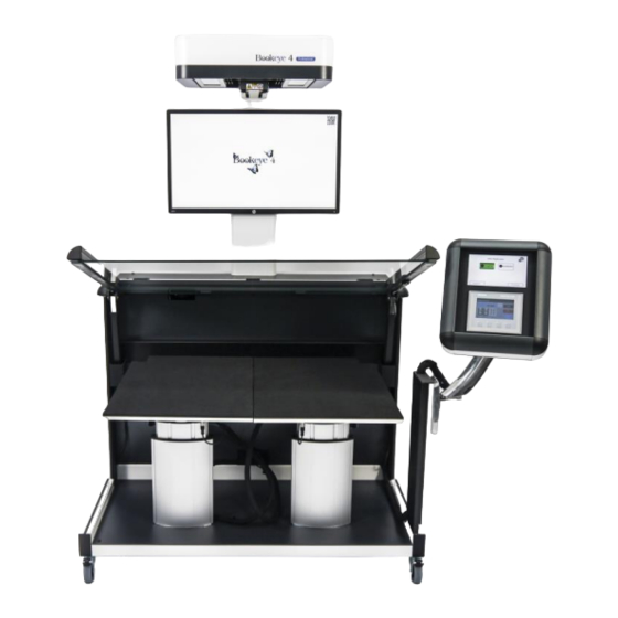
Device Overview B.1.1 Front Side Elements Picture 1: Elements of the Bookeye 4-V1A C35 Some of the major components of the scanner have been identified in the above picture. These components are referenced in this operation manual. The main hardware elements are: Camera head. -
Page 15: Connectors On The Rear Side
B.1.2 Connectors on the Rear Side For easy orientation, the connectors found on the rear side of the scanner are depicted in the following picture and described below. Picture 2: Connectors on the rear side Main power switch with integrated power cable connector Network connector. -
Page 16: Connecting The Power Source
Connecting the Power Source Before connecting the scanner to the external power source check the following items: Ensure the electrical outlet is in perfect condition and that it is properly grounded. Ensure that the electrical outlet is equipped with a fuse with the proper capacity. -
Page 17: 4-V1A C35
Bookeye 4-V1A C35 ® B.2.1 Starting the Bookeye 4-V1A C35 has two power switches, one at its rear side and one on the right ® side (see Picture 2). The main power switch turns on the power for the motor-powered lifting columns, the motor- powered glass plate and the TFT flat screen and the scanner unit. -
Page 18: Picture 4 Usb Connectors And Standby Button
Bookeye 4-V1A C35 scanner unit ® The red illumination of the standby button signals that the is in standby mode. Picture 4 USB connectors and standby button Press the standby button to start the scanner unit. The button illumination changes to blue. The scanner starts with self test routines and verifies all system components. -
Page 19: Switching To Standby Mode
B.2.2 Switching to Standby Mode Always use the “Standby” button to switch the scanner to IMPORTANT: standby mode. Press and hold the standby button for at least three seconds. While pressing the button, a “click” sound is audible. During the shut down sequence, the TFT flat screen and the upper touchscreen of the dual display show the scanner name and version and a progress bar. -
Page 20: C Hardware Operation
Hardware Operation Bookeye 4 V1A C35 scanner is equipped with two motor-powered lifting columns and ® a motor-powered glass plate. The integrated Scan2Net software as well as an external scan application allow the user to scan a wide range of documents with brilliant quality and a high throughput. The scanner settings can be defined by the upper touchscreen. -
Page 21: Picture 6: Book Cradles In V Position, Glass Plate Open
… or V position. Picture 6: Book cradles in V position, glass plate open The V position is recommended for very delicate, old books and other documents that cannot take up a flat position. The opening angle of the book cradle is 140 degrees. IMPORTANT: Before setting the book cradle to V position, press INIT on the lower Simatic touchscreen. -
Page 22: Upper Touchscreen
Upper Touchscreen The Scan2Net kiosk user interface is structured in four sections, which allow operators to control and select various functions of the scanner. Picture 7: Viewer & Job Control screen The touchscreen is structured in four sections, which allow operators to control and select various functions of the scanner. -
Page 23: Lower Simatic Touchscreen
Simatic Touchscreen The content displayed in the touchscreen varies depending on the selected scan mode. If a function is not available in a specific scan mode, the control symbols greyed out. Picture 8: Start menu touchscreen The lower touchscreen enables the operator to select one of three scan modes, to move the book cradle plates up and down separately, to initialize the book cradles and the glass plate,... -
Page 24: Activating The Parameter Menu
Activating the Parameter Menu Important! While the Admin mode is active, do not select the VSCAN (F2) scan mode in the start menu. The opening angle of the glass plate will override the defined limit. Severe damage to the glass plate can result. To avoid damages, please do not change any parameters in the parameter menu! Press the button “F4”... -
Page 25: Touchscreen Parameter Table
CALIBRATE The maximum lifting height of the lifting columns is limited by a light barrier. The light barrier is positioned in the upper part of the bottom unit. To place the calibration target in the correct position, it must be pressed to the bottom side of the closed glass plate. - Page 26 SLOW L1: Defines the speed when moving the lifting columns L1 and L2 SLOW L2: up-/downwards while the light barrier detects them. POS L1 Shows the height of the lifting columns, measured from the POS L2 zero point POS L3 Shows the opening height of the glass plate, measured from the fully closed position.
-
Page 27: D Software Operation
Software Operation Lower Touchscreen Scan Modes Bookeye 4 V1A C35 scanner offers three automated scan modes. They can be ® selected by the three buttons in the bottom row. BOOKSCAN The opened glass plate will be closed automatically before the scan sequence starts. -
Page 28: White Balance Adjustment
White Balance Adjustment 1. First, press the “INIT” button on the lower Simatic touchscreen to initialize the book cradle and the glass plate. See picture 8, arrow number. 3. 2. Choose the book mode on the Simatic touchscreen. See Picture 8, arrow 1. 3. -
Page 29: Picture 12: Symbol To Activate The Setup Menu
7. Activate the Setup Menu on the Scan2Net touchscreen To activate the setup menu, tap the gear icon in the upper-right corner of the touchscreen (see red circle). Picture 12: Symbol to activate the setup menu On the next screen, enter user login and password. The default user login is Poweruser, the default password is Poweruser as well. -
Page 30: Picture 14: Setup Menu, White Calibration
The screen content changes and shows the setup menu for white calibration. Perform the white calibration with the glass plate closed by using the “Calibrate GP button”. Picture 14: Setup menu, white calibration 8. Move the glass plate upwards with the “Lift 3” upper arrow button. While pressing on the arrow up button, a login mask will be shown. -
Page 31: The "Finger Removal" Function
The “Finger Removal” Function D.3.1 Position of Document Bookeye 4 scanner offers a helpful function which detects fingers at the margin of ® books and eliminates them from the image. This is the “Finger Removal” function. The following simple steps must be completed to operate the scanner using the “Finger Removal”... -
Page 32: Finger Positions
D.3.2 Finger Positions Another important criteria for a proper function of the “Finger Removal” function is the position of the fingers when holding the book in a flat position. • The fingers must be positioned in a vertical area of max 1 inch = 25 mm width measured from the book fan at each side of the book. -
Page 33: D.3.3 Wrong Finger Positions
D.3.3 Wrong Finger Positions Some finger positions can cause malfunction of the “Finger Removal” function. The following chapters show a few examples of wrong and correct finger positions. D.3.3.1 Distance too small The fingers should be positioned with distance to the text or to graphical elements in the document. - Page 34 D.3.3.3 Fingers held too close to the margin of the document When the fingers are held too close to the document’s margin, they will not be removed by the “Finger Removal” function. Wrong Correct Move the fingers in small steps from the edge of the document to the inside and repeat the scan sequence.
-
Page 35: D.3.4 Examples Of Finger Removal
D.3.4 Examples of Finger Removal Some examples in the following chapter show the functionality of the “Finger Removal” function. Finger Removal is available in all document modes A requirement is that the scanner is set to Book Mode in the ScanWizard application or the external software. - Page 36 Book Mode, Finger Removal Mode: On, Finger Removal Color: Black Note: The Finger Removal Color is defined in the ScanWizard user interface. Book and finger position Scan result The resulting image now shows the area where the finger contour was detected. The detected area is filled with a solid black color.
- Page 37 Large book (e.g. catalogue) kept flat by single finger Book Mode, Finger Removal Mode: On, Finger Removal Color: Auto Note: The Finger Removal Color is defined in the ScanWizard user interface. Book and finger position Scan result The book fan has been removed and the surrounding black area is reduced to a minimum. The scan result shows a part of the finger in the lower left corner.
-
Page 38: D.3.4.3 Multiple Fingers Hold The Book
D.3.4.3 Multiple fingers hold the book Book Mode, Finger Removal Mode: Book Fan Book and multiple fingers position Scan result Small book kept flat by multiple fingers Book Mode, Finger Removal Mode: On, Finger Removal Color: Auto Note: The Finger Removal Color is defined in the ScanWizard user interface. If parts of the content of the book are covered by a finger or by multiple fingers, the removal function detects the contour and fills the area with the selected fill option. - Page 39 Book Mode, Finger Removal Mode: On, Finger Removal Color: Auto Note: The Finger Removal Color is defined in the ScanWizard user interface. Book and multiple fingers position Scan result The position of the three fingers has been detected. The fingers contour is eliminated in the resulting image and filled with a pattern and/or color. If Finger Removal Color is set to Auto the filling color and/or pattern is automatically taken from the area above and below the finger contour.
-
Page 40: D.3.4.4 Small Books With Pattern At Margin
D.3.4.4 Small books with pattern at margin If a book has small dimensions, the finger removal mode Book Fan very often delivers good results without flattening the book by fingers. Book Mode, Finger Removal Mode: Book Fan Book position Scan result The scan result shows the content of both pages. -
Page 41: Picture 20: Login Screen
The Setup Level The setup level is divided into three access levels. The access levels Poweruser and Admin are password protected. The User access level allows showing certain information about the system such as power up time, remaining lamp life time or firmware version. Furthermore, the access level User allows setting some basic parameters. -
Page 42: Picture 21: User Screen
Access Level User Click the button User . This will open the below displayed screen. Picture 21: User screen The user screen is divided into two sections. The section Device Information shows some details of the scanner and gives general operation information. -
Page 43: Picture 22: Device Info Screen
E.1.1 Device Info In the section Device Information, click the button Device Info and the following list (Fehler! Verweisquelle konnte nicht gefunden werden.) will be displayed. Click the buttons below the headline Device Info to get specific scanner information. Picture 22: Device Info screen Bookeye 4 scanner. -
Page 44: Picture 24: Operation Info Screen
E.1.2 Operation Info In the section Device Information, click the button Operation Info and the following list will show various scan counters and elapsed times. Picture 24: Operation Info screen The following table provides a brief description of the operation information. Field Description Scan Count... -
Page 45: Picture 25: User Settings Start Screen
E.1.3 User Settings In the section User Settings, click the button User Settings and the following screen will be displayed. Picture 25: User Settings start screen Power Saving screen will be displayed as start screen of the User Settings section. Click the links below the headline to set the respective parameters. -
Page 46: Picture 26: Language Selector Screen
E.1.3.1 Language Selector Use the function Language Selector to set the language for the user interface and the OCR Bookeye 4 scanner. ® language of the Picture 26: Language Selector screen Click on the selection arrow beside Language and a list of available languages opens. Select the desired language for the user interface with a mouse click. -
Page 47: Picture 27: File Name
E.1.3.2 File Name Use the function File Name to define a default file name. Picture 27: File name When defining the default file name, variables can be used. To see a list of the variables, click the link Wildcard characters. Picture 28: List of wildcard characters Below the field “File Name”, the defined file name is displayed. -
Page 48: Picture 29: Power Saving
E.1.3.3 Power Saving Click the button Power Saving to set the timers for the standby modes and the standby method. The available settings are displayed on the screen. Picture 29: Power Saving Click on the selection arrow to open the list of available values for the respective standby mode. -
Page 49: Picture 30: Volume Level
E.1.3.4 Volume Click the button Volume to set the loudspeaker’s volume of the scanner. Picture 30: Volume level A screen opens and shows a graphic to symbolize the volume level. Click on the scale to set the volume level or right click with the mouse at the arrow and move the arrow to the desired value while holding the mouse button pressed. -
Page 50: Picture 31: Foot Pedal Settings
E.1.3.5 Foot Pedal Click the button Foot Pedal to define a function for the foot pedals. Picture 31: Foot pedal settings The scanner has connectors on its rear side to connect a foot pedal. The symbol for the second foot pedal will be used in a later firmware version. Click below the symbol of Pedal FS-1 or Pedal FS-2 and select from the drop-down list which action should be executed when the pedal is operated. -
Page 51: Picture 33: Ocr Information
E.1.3.6 Click the button OCR in order to select the OCR engine from the list. If there is no OCR engine available, the screen displays a message that no OCR engine has been found. If no OCR engine is installed, the screen displays a message that no engine is installed. Picture 33: OCR information Picture 34: Splitting start page To return to the Login screen click the button... -
Page 52: F Technical Data
Technical Data Scanner Specifications Scan Area / Document Size Maximum scan area 635 x 850 mm (25 x 33.5 inch) Scanner resolution 600 x 600 dpi Optical resolution 600 x 400 dpi Minimum document size 100 x 100 mm / 4 x 4 inch Illumination Light intensity while scanning: Max. -
Page 53: F.2 Electrical Specifications
Electrical Specifications Connection 100 – 240 V AC Voltage Frequency 50/60 Hz Power Consumption Standby 25 W Ready to scan, monitor on 110 W Scanning 150 W ≤ 330 W Fully automatic scan cycle Dimensions and Weight Scanner dimensions 1700 x 1100 x 960 mm (H x W x D) 67 x 43.3 x 37.8 inch Total weight of scanner, ready to use Approx.
Need help?
Do you have a question about the Bookeye 4 and is the answer not in the manual?
Questions and answers