Image Access Bookeye 4 Setup Manual
Hide thumbs
Also See for Bookeye 4:
- Operation manual (122 pages) ,
- Operation manual (53 pages) ,
- Installation manual (34 pages)
Table of Contents

Related Manuals for Image Access Bookeye 4


Summary of Contents for Image Access Bookeye 4
- Page 1 Setup Manual...
-
Page 2: Table Of Content, Part
File: BE4-V1A_SetupManual_A.docx... -
Page 3: Table Of Content, Part
Image Access. All other trademarks are the property of their respective owners. Image Access reserves the right to change the described products, the specifications or documents at any time without prior notice. For the most recent version, always check our web site www.imageaccess.de... -
Page 4: Introduction
Dear Customer, We congratulate you on the acquisition of this innovative product from Image Access. We at Image Access are proud of the work we do; it is the result of our extremely high standards of production and stringent quality control. -
Page 5: About The Manual
“Power user”. This “Power user” level is password protected from access by the normal operator. All manuals can be downloaded from the Image Access customer service portal at http://portal.imageaccess.de. Be sure to always check for the latest versions of these manuals. -
Page 6: Version History
Version History Version Published in Content/Changes/Supplements November 2013 First version. Page 6 Setup Manual... -
Page 7: Table Of Contents
Starting the Bookeye 4 B.3.2 Switching the Bookeye 4 to Standby Mode F-B.2 Raccordement à l'alimentation électrique ..........30 F-B.2.1 Mise en marche du Bookeye 4 F-B.2.2 Commutation du Bookeye 4 sur le mode de veille Setup Manual Page 7... - Page 8 Table of Content, part 2 C Setup and Adjustments --------------------------------------------------- 32 White Balance ..................33 Focus and Scan Area ................34 C.2.1 Auto focus Scan Start DPI Adjust Gear Correction C.2.2 Laser Check Test Suite ....................36 IP Address ....................37 User Settings ...................
- Page 9 Table of Content, part 3 D.4.2 Network Configuration D.4.2.1 IP Configuration Method D.4.2.2 IPv4 (Network Interface 0) D.4.2.3 IPv4 (Network Interface 1) D.4.2.4 Domain Name Server D.4.2.5 SMB Settings D.4.2.6 Wireless LAN (Basic Settings) D.4.2.7 Wireless LAN (LAN Interface) D.4.2.8 Wireless LAN (Security) D.4.2.9 Wireless LAN (DHCP)
- Page 10 Table of Content, part 4 Adjustments & Support ................117 D.6.1 Adjustments D.6.1.1 Auto Focus D.6.1.2 Focus Line D.6.1.3 Scan Start D.6.1.4 DPI Measurement D.6.1.5 Center Measurement D.6.1.6 Lamp Test D.6.1.7 Laser Check D.6.1.8 White Balance D.6.1.9 Delete White Balance Data D.6.1.10 Brightness Correction D.6.1.11...
-
Page 11: Setup Manual Page
Table of Content, part 5 E Technical Data / Caractéristiques techniques -------------------- 143 Scanner Specifications ................143 F-E.1 Spécifications du scanner ............... 144 Electrical Specifications ................145 F-E.2 Spécifications électriques ............... 146 Dimensions and Weight ................147 F-E.3 Dimensions et poids ................147 Ambient Conditions ................. - Page 12 Table of Pictures Picture 1: Bookeye 4 scanner in transport box ..............21 Picture 2: Inside view of transport box ................22 Picture 3: Scanner outside the transport box ..............23 Picture 4: Plastic bags removed from scanner ..............23 Picture 5: Elements of the Bookeye 4-V1A ..............
-
Page 13: Setup Manual Page
Table of Pictures, part 2 Picture 36: Document cache selector ................57 Picture 37: Kiosk App selection ..................58 Picture 38: Set Watermark position ..................59 Picture 39: Show Warnings selector ................59 Picture 40: IP Configuration Method ................60 Picture 41: Settings of IPv4 (Network Interface 0) ............61 Picture 42: Settings of IPv4 (Network Interface 1) ............62 Picture 43: Domain Name Server parameters ..............64 Picture 44: SMB Settings ....................65... - Page 14 Table of Pictures, part 3 Picture 71: USB Device parameters ................96 Picture 72: Template list for Metadata ................98 Picture 73: Metadata parameters ..................99 Picture 74: Template list for PDF document ..............100 Picture 75: PDF Document parameters ................. 101 Picture 76: LDAP Directory Service templates ...............
-
Page 15: Setup Manual Page
Table of Pictures, part 4 Picture 106: Laser Check, optional measurement ............124 Picture 107: Laser check result with book cradle in V-position ........124 Picture 108: Test target placed in the middle ..............125 Picture 109: White Balance results ................125 Picture 110: Information about deleting the white balance data ........ -
Page 16: A Safety Notes
Safety Notes Safety Notes Read and ensure that you understand the safety notes. The safety notes have been written to ensure your protection and for your safety. Follow all safety notes to avoid damage to the device. A.1.1 Marking of Safety Notes All safety notes are marked with a warning sign. -
Page 17: F-A.1 Notes De Sécurité
F-A.1 Notes de sécurité Lisez ces notes de sécurité et veillez à bien les comprendre. Ces notes ont été rédigées pour assurer votre protection et votre sécurité. Respectez toutes les notes de sécurité pour éviter d’endommager le dispositif. F-A.1.1 Marquage des notes de sécurité Toutes les notes de sécurité... -
Page 18: Safety Precautions
Image Access Technical Support. The scanner should be used only with the power supply that is delivered with the scanner. If you are unsure, please contact the Image Access Technical Support. 10. Image Access recommends plugging the scanner into an appropriately rated power outlet. -
Page 19: F-A.2 Précautions De Sécurité
En cas de doute, veuillez contacter l’Assistance Technique de Image Access. 10. Image Access recommande de brancher le scanner sur un climatiseur électrique d’une puissance appropriée. 11. Coupez toujours l’alimentation électrique et débranchez le cordon d’alimentation de la prise de courant murale avant de nettoyer le scanner. -
Page 20: In General
In General This setup manual describes the settings and functions using a device equipped with all options. Deviations to other devices with other equipment or reduced options are possible. Certification Bookeye ® 4 scanner: All safety requirements of the following standards are fulfilled by the IEC 60950-1, International Safety Standard for Information Technology Equipment UL 60950-1, Safety for Information Technology Equipment (US standard) CAN/CSA C22.2 No.60950-1, Safety for Information Technology Equipment... -
Page 21: B Hardware
Hardware Content on Delivery The scanner is delivered in a wooden transport box. Picture 1: Bookeye 4 scanner in transport box In addition to the scanner, the transport box also contains Reference folder with four CSTT-1 reference targets. Three White Reference targets BE4-WA-V1-A (640 x 180 mm). -
Page 22: Unpacking The Scanner From The Transport Box
B.1.1 Unpacking the Scanner from the Transport Box The scanner is placed in the transport box on a wooden slide-in with specially formed foam plastic elements. The transport box interior is divided into two parts by a thin wooden plate below the camera head. -
Page 23: Picture 3: Scanner Outside The Transport Box
Lift the scanner from the wooden slide-in and place it on a sturdy table. The bearing capacity of the table should be at least double of the scanner’s weight. Picture 3: Scanner outside the transport box Remove the plastic bags from camera head and scanner base unit. Picture 4: Plastic bags removed from scanner The TFT monitor is protected with a bubble wrap (3) between monitor and glass plate. -
Page 24: Device Overview
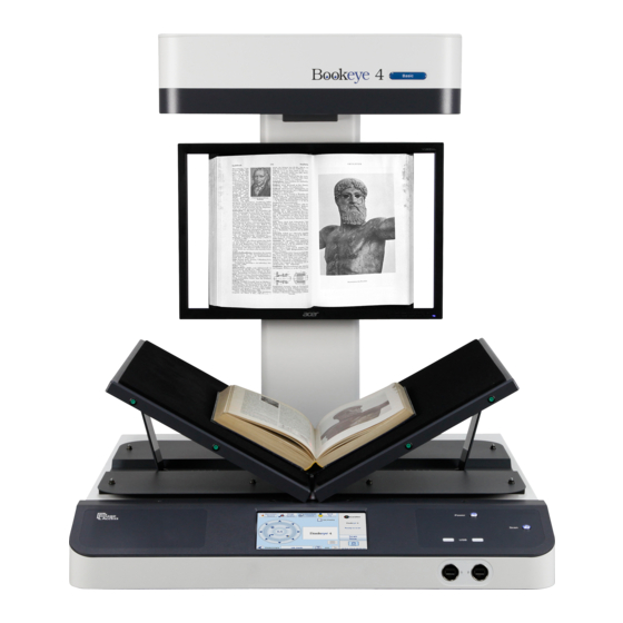
Device Overview Picture 5: Elements of the Bookeye 4-V1A Bookeye 4 scanner have been identified in the ® Some of the major components of the above picture. These components are referenced in this operation manual. Bookeye ® 4 scanner main hardware elements are: 7 inch WVGA touchscreen: The touchscreen shows all menus and provides access to all functions directly from the scanner. -
Page 25: Connectors On The Rear Side
B.2.1 Connectors on the Rear Side For easy orientation, the connectors found on the rear side of the scanner are depicted in the following picture and described below. Picture 6: Connectors on the rear side Connector for Recovery key. Main power switch. Set the main power switch to position I to set the Bookeye ®... -
Page 26: F-B.1 Aperçu Du Dispositif
F-B.1 Aperçu du dispositif Photo 1: Eléments du Bookeye 4 Bookeye 4 ont été identifiés sur la photo ® Certains des éléments essentiels du scanner ci-dessus. Ces éléments sont des références dans ce manuel d’utilisation. 1. Ecran tactile : L’écran tactile affiche tous les menus utilisés pour paramétrer et Bookeye ®... -
Page 27: Connecteurs Sur Le Côté Arrière
F-B.1.1 Connecteurs sur le côté arrière Pour faciliter l’orientation, les connecteurs du côté arrière du scanner sont illustrés sur la photo ci-après et décrits ci-dessous. Photo 2: Connecteurs sur le côté arrière Port série / connecteur de la clé de récupération. Interrupteur électrique principal. -
Page 28: Connecting The Power Source
Connecting the Power Source Before connecting the scanner to the external power supply and the power supply to the electrical outlet, check the following items: Ensure the electrical outlet is in perfect condition and that it is properly grounded. Ensure that the electrical outlet is equipped with a fuse with the proper capacity. -
Page 29: Switching The Bookeye 4 To Standby Mode
TFT flat screen and on the touchscreen. At the end of the startup sequence, the touchscreen and the TFT flat screen display the start screen. B.3.2 Switching the Bookeye 4 to Standby Mode Bookeye ® 4 under normal working conditions,... -
Page 30: F-B.2 Raccordement À L'alimentation Électrique
F-B.2 Raccordement à l'alimentation électrique Avant de raccorder le scanner à l’alimentation électrique extérieure, et donc à la prise de courant, vérifiez les points suivants: Veillez à ce que la prise de courant soit en parfait état et qu’elle est correctement mise à... -
Page 31: Mise En Marche Du Bookeye
Des messages d’état seront affichés sur l’écran plat TFT et sur l’écran tactile. A la fin de la séquence de démarrage, l’écran tactile affiche l’écran de démarrage. F-B.2.2 Commutation du Bookeye 4 sur le mode de veille Bookeye ®... -
Page 32: C Setup And Adjustments
Setup and Adjustments Bookeye ® 4 allows some adjustments to be made directly via the touchscreen, e.g. autofocus settings and White Balance calibration. Furthermore, the IP address can be configured and other user settings can be defined. To enter the setup menu, tap the touchscreen at the date and time section ten times successively. -
Page 33: White Balance
White Balance Picture 9: Setup menu, start screen The first menu item of the setup menus is the White Balance screen. Whenever it is necessary to perform a White Balance calibration, the touchscreen shows how to position the reference target and the book cradles for optimal calibration. To execute the White Balance calibration, close the book cradles and place the reference target BE4-WA-V1-A as shown. -
Page 34: Focus And Scan Area
Focus and Scan Area Picture 10: Focus and Scan Area menu The Focus and Scan Area menu contains five buttons for measurement purposes. When touching one of the five buttons, the picture on the touchscreen changes. It shows how the book cradles and/or the reference target must be positioned. C.2.1 Auto focus Scan Start... -
Page 35: Laser Check
C.2.2 Laser Check Picture 12: Reference target position The book cradles must be closed. The reference target BE4-WA-V1-A must be placed on the book cradles as shown in the picture. The markers in the middle of the long side of the reference target should be covered by the vertical laser line. -
Page 36: Test Suite
Test Suite Picture 13: Testsuite The Testsuite menu delivers information about the following parameters: Foot pedal status: Active = Foot pedal connected Inactive = No foot pedal connected Temperature of CPU core 0 and CPU core 1. Available voltages for the mainboard and at the mainboard: •... -
Page 37: Ip Address
IP Address Picture 14: IP Address mask To set the parameter of IP address, gateway, and netmask, touch the number in the in the respective line. Touch the desired position in the respective row to move the cursor to that position. To delete a digit, place the cursor right beside of the digit and press the “<=”... -
Page 38: User Settings
User Settings Picture 15: User Settings menu The User Settings menu allows defining the touchscreen menu parameters. Language selector The currently selected language is displayed. The touchscreen menu language can be selected by touching the selection arrow. A list opens, showing the available languages. - Page 39 Display standby after Sets the time of inactivity after the external display and the touchscreen switches to standby. The touchscreen and the external display turn to black. They will return after pressing the standby button or touching the touchscreen. Screen Saver after Sets the time of inactivity after the screen saver is activated.
-
Page 40: Change Gui
C.5.1 Change GUI Picture 16: Selectable presets The Change GUI menu shows all predefined settings (presets). By default, the presets Easy and Expert are defined. Picture 16 shows as an example some additional presets. Selecting App Selection switches the touchscreen to the system start screen, followed by a selection screen with the presets. -
Page 41: Time And Date
Time and Date Picture 18: Time and Date To change the time or date value, touch the value in the respective line. Touch the line at the desired position to move the “cursor”. To delete a digit, place the cursor at the right side of the digit and press the “<=” button. The digits will always be deleted from right to left. -
Page 42: User Preset
User Preset Picture 19: User preset screen Preset Selection A preset contains the elements used in the kiosk application to control the scanner. Select here the preset that should be used when selecting the kiosk application in the start screen of the touchscreen. Touch the selection arrow to open the list and to select a preset. -
Page 43: D The Poweruser Level
The Poweruser Level To enter the Poweruser level, start your browser and enter the IP address of the scanner. Picture 20: Scan2Net Start Screen The start screen shows three symbols, which lead to the main categories of the Scan2Net user interface. Launch Scan Application changes to the main screen of the user interface. -
Page 44: Setup Menu
Setup Menu The login level screen shows the buttons of the login level. All login levels except the level User are password protected. The button Launch Scan Application starts the Scan2Net scan application. The button Back returns to the former screen. Picture 21: Login level screen D.1.1 Selecting the Login Level... -
Page 45: Picture 22: Poweruser Log-In Menu
In the login level screen, choose the login level Poweruser . Picture 22: Poweruser log-in menu Enter as user name and password: Poweruser Consider the case sensitivity of user name and password. Click the button Apply to finish the entry. Setup Manual Page 45... -
Page 46: Main Menu
Main Menu The main menu of the Poweruser level contains all menus of the User level. The Poweruser start screen is structured in six sections. Picture 23: Main menu Poweruser level The buttons below the section titles name the parameters which can be set or modified in the respective section. -
Page 47: Navigating Through The Menus
D.2.1.1 Navigating through the menus The bottom line of each screen shows two buttons at the right side: Setup Menu Returns to the login screen. Launch Scan Application Switches to the main screen of the integrated Scan2Net user interface In each selection menu screen below the parameter to be set, the following button is displayed: Returns to the Poweruser level start menu (Picture 23). -
Page 48: Device Information
Device Information Device Information The section gives basic information about the scanner. This section is divided in two parts. D.3.1 Device Info Device Info lists the hardware components and provides information about the settings for printer configuration, SMB configuration and many more. To find the information, click the respective links. -
Page 49: Base Settings
Base Settings Base Settings section contains the basic parameters of the scanner. D.4.1 User Settings The section User Settings is divided into subsections. The User Settings start screen is the Power Saving screen. The following description starts with the Language Selection screen. D.4.1.1 Language Selection Language Selector Use the function... -
Page 50: File Name
D.4.1.2 File Name Please note: Available from firmware version 6.08. File Name Use the function to define a default file name when saving scanned images. Picture 27: File Name settings Variables can be used in the file name. Click at the link Wildcard characters to list the available variables. -
Page 51: Power Saving
D.4.1.3 Power Saving Note: Power Saving User Settings screen is the start screen of the section. Power Saving Use the function to set the timers for the standby modes. Four settings can be defined. Power Saving. Click on the link Picture 28: Power Saving Click on the selection arrow to open the list of available values for the respective standby mode. -
Page 52: Volume
D.4.1.4 Volume Volume Use the function to set the volume level of the loudspeakers volume in the scanner. Picture 29: Volume level A screen opens and shows a graphic to symbolize the volume. Click on the percentage value to change the volume level. The color of the graphic will change depending on the selected volume level. -
Page 53: Foot Pedal
D.4.1.5 Foot Pedal Foot Pedal Use the function to define an action for the foot pedals. Picture 30: Foot pedal settings The scanner has two connectors on its back to connect foot pedals. Click below the symbols and select from the drop-down lists which action should be executed when a pedal is operated. -
Page 54: Glass Plate
D.4.1.6 Glass Plate Glass Plate Click the button to define the action of the scanner when the glass plate lock is engaged. Picture 32: Shows glass plate parameters if installed Start scan defines if the scanner starts scanning after the glass plate lock is engaged. Start scan? Yes: The scan sequence starts after the glass plate lock is engaged. -
Page 55: Display
D.4.1.7 Display Display Use the function to define the resolution of the external monitor and to select an ICC profile. Picture 33: Display parameters Bookeye ® 4 scanner comes with an external monitor with a resolution of 1366 x 768 pixels by default. -
Page 56: Splitting Start Page
D.4.1.8 Splitting Start Page Splitting Start Page Use the function to define the page which is displayed first, when Splitting Image is set to Auto in the Scan2Net user interface. See the Operation Manual, description of Properties Splitting Image. Picture 34: Splitting start page The selected start page is highlighted. -
Page 57: Secure File Erasing
D.4.1.9 Secure File Erasing New with software 6.x or higher. This menu item allows selecting the erasing method for files stored in the scanner memory. Picture 35: List of available erasing methods Click on the selection arrow to open the list of erasing methods. Select the desired method by clicking on the methods name. -
Page 58: Kiosk App
D.4.1.11 Kiosk App Kiosk App Use the function to define how the scanner behaves when starting. Picture 37: Kiosk App selection Show Application menu: With factory settings, the scanner’s touchscreen shows at the end of the start sequence the buttons for the applications EasyScan and Scan2Net. By touching the respective button, the scanner starts with the selected application. -
Page 59: Watermarks
D.4.1.12 Watermarks Watermarks Use the function to set the position of the watermark text in the image. Picture 38: Set Watermark position Select from the list the desired position of the watermark text. The watermark will be inserted in every image at the defined position. The watermark text itself can be defined by clicking on the button Watermarks in section Updates &... -
Page 60: Network Configuration
D.4.2 Network Configuration Network Configuration The section is divided in nine subsections. The Network Configuration start screen is the IPv4 (Network Interface 0) screen, which is described in chapter D.4.2.2. The following description starts with the IP Configuration Method screen. D.4.2.1 IP Configuration Method IP Configuration Method The function... -
Page 61: Ipv4 (Network Interface 0)
D.4.2.2 IPv4 (Network Interface 0) IPv4 (Network Interface 0) The function allows the operator modifying the parameters for the “Network Interface 0”. This is the primary network and is used for communication with external network devices. Picture 41: Settings of IPv4 (Network Interface 0) The screen shows the parameters for “Network Interface 0”. -
Page 62: Ipv4 (Network Interface 1)
D.4.2.3 IPv4 (Network Interface 1) IPv4 (Network Interface 1) The function allows the operator modifying the parameters for the “Network Interface 1”. This is the secondary network and used for communication with internal network devices, e.g. the WLAN module. Picture 42: Settings of IPv4 (Network Interface 1) The screen shows the parameters for the “Network Interface 1”. - Page 63 D.4.2.3.1 Solving a routing conflict in a network As said before, the “Network Interface 0” is used for the communication with external networks; “Network Interface 1” is used for the internal communication with the WLAN module. If the scanner should be operated in an existing network that is configured in the IP address range 10.0.0.x/24 or 10.0.x.x/16 and a host with the IP address 10.0.0.1 is used in this network, a routing conflict will occur.
-
Page 64: Domain Name Server
D.4.2.4 Domain Name Server Domain Name Server. This section defines the parameters for the Picture 43: Domain Name Server parameters Domain Name Enter the domain name here. Primary DNS Server Enter the address of the primary DNS server here. Secondary DNS Server Enter the address of the secondary DNS server here. -
Page 65: Smb Settings
D.4.2.5 SMB Settings Settings. This section defines the parameters for the Picture 44: SMB Settings Note: The default settings are recommended. SMB Hostname Enter an SMB host name to identify the scanner in the network. Default is the MAC address of the scanner. SMB Workgroup Enter the SMB workgroup in which the scanner is installed. -
Page 66: Wireless Lan (Basic Settings)
D.4.2.6 Wireless LAN (Basic Settings) Wireless LAN (Basic Settings) Use the function to define the basic settings for the WLAN module. Note: This menu is displayed only if a WLAN module is installed and if the settings for IPv4 (Network Interface 1) Wireless LAN (LAN Interface) fit together. -
Page 67: Wireless Lan (Lan Interface)
D.4.2.7 Wireless LAN (LAN Interface) Wireless LAN (LAN Interface) Use the function to define the parameter of the secondary LAN interface of the motherboard. This interface is used to connect the Wireless LAN module with the motherboard.. Note: This menu is displayed only if a WLAN module is installed and if the settings for IPv4 (Network Interface 1) Wireless LAN (LAN Interface) fit together. -
Page 68: Wireless Lan (Security)
D.4.2.8 Wireless LAN (Security) Wireless LAN (Security) Use the function to define the parameters for wireless LAN security. Note: This menu is displayed only if a WLAN module is installed and if the settings for IPv4 (Network Interface 1) Wireless LAN (LAN Interface) fit together. -
Page 69: Wireless Lan (Dhcp)
D.4.2.9 Wireless LAN (DHCP) Wireless LAN (DHCP) Use the function to define the range of IP addresses that can be used by the WLAN module for DHCP access. Note: This menu is displayed only if a WLAN module is installed and if the settings for IPv4 (Network Interface 1) Wireless LAN (LAN Interface) fit together. -
Page 70: Adjust Time & Date
D.4.3 Adjust Time & Date The section Adjust Time & Date is divided into subsections. The Adjust Time & Date start screen is the Manual Adjustment screen. The following description starts with the Time Format screen. To set the time correctly for the scanner, make the adjustments in the following order. Select the time zone. -
Page 71: Time Format
D.4.3.1 Time Format The time shown in the headline of the Scan2Net user interface can be displayed in either 12h or 24h format. Picture 49: Time Format Click on the selection arrow. The differences between 12h and 24h format are shown below. -
Page 72: Time Zone
D.4.3.2 Time Zone Time Zone Use the function to define the time zone for the internal clock of the scanner. Picture 50: Time Zone screen Click on the selection arrow. A list opens. Select the desired time zone from the list. The list will close and the selected setting is effective immediately. -
Page 73: Ntp Server
D.4.3.4 NTP Server NTP Server Use the function to define the address of time server. Picture 52: NTP Server setting To connect to a NTP server, the scanner must have a connection to the internet. Ask your network administrator for special information concerning your local network. Enter the address of the NTP server in the line NTP server. -
Page 74: Sound System
D.4.4 Sound System The section Sound System is divided into three subsections. The Sound System start screen is the Set Volume screen. D.4.4.1 Set Volume Set Volume Use the function to set the loudspeakers volume of the scanner. Picture 53: Set Volume A screen opens and shows a graphic to symbolize the volume. -
Page 75: Sound Files
D.4.4.2 Sound Files Sound Files Use the function to list the sounds which are linked to system events. Picture 54: Sound Files list Scroll to the bottom of the list to search and upload new sounds to the scanner. Picture 55: Upload new sound files Click on the button Search to search the directories of your local PC and/or your network for sound files. -
Page 76: Link Events
D.4.4.3 Link Events Link Events Use the function to change the sounds linked to system events. Picture 56: Link Events list The sound file that is listed at each event is dependent on the language set for the scanner (see chapter D.4.1.1). To identify the language of the sound file, an identifier can be added to the file name. -
Page 77: Installed Options
To activate an option, a unique key must be entered. The key is valid only with one specific scanner and cannot be transferred to another scanner. The software keys can be purchased at the Image Access Customer Service Portal. Visit the URL portal.imageaccess.de... -
Page 78: Templates
D.4.6 Templates The section Templates contains all settings for the data output. By clicking at the links from Remote Printer USB Device Configuration the current settings for the respective output channel can be displayed. The links Metadata LDAP Directory Service allow defining up to five individual allows defining one individual setting. -
Page 79: Exclusion Of Wildcard Characters For Jobmode Scanning
D.4.6.1 Exclusion of Wildcard Characters for Jobmode Scanning Please note: Valid for firmware before V 6.08. The number of variables which can be used for creating file names while scanning in jobmode is limited. When scanning in jobmode, the information for some variables is taken from the last scanned image and is used for naming the selected images respectively the ZIP archive file. -
Page 80: Remote Printer
D.4.6.2 Remote Printer Picture 60: Template list for remote printer The data output Remote Printer sends the images after scanning to a previously defined network printer. Page 80 Setup Manual... -
Page 81: Picture 61: Remote Printer Parameters
D.4.6.2.1 Setup Picture 61: Remote printer parameters Parameter Description Choose between IP Networking and SMB Printer Queue. Connection Type Address Enter the IP address of the printer. (with IP Networking only) Port (9100) Enter the IP port of the remote printer. Default is port 9100. (with IP Networking only) Connection Timeout Choose the timeout for connecting to the remote printer... - Page 82 Remote Printer, continued Parameter Description Select Homegroup Network or Workgroup Network. Network Type (with SMB Printer Queue only) Password Enter the password for the Homegroup Network. (with SMB Printer Queue Homegroup Network only) Select Yes or No. Server Authentication (with SMB Printer Queue ...
- Page 83 Remote Printer, continued Parameter Description Duplex Print Switch on/off printing on both sides of a sheet (duplex). (not with HP Design Jet) Select between Book and Notepad. Duplex Mode Book = binding at the wide side of the paper sheet Notepad = binding at the narrow side of the paper sheet Paper Feed Select the paper feed method for the remote printer.
- Page 84 Accounting Only available with Konica Minolta Bizhub Series Parameter Description Yes / No Accounting Account Name Enter the account name here. Yes / No Use Password Account Password Enter the password for the accounting here. Yes / No Hold Job Public / Private Job Type Hold Key...
-
Page 85: Ftp Server
D.4.6.3 FTP Server Picture 62: Template list for FTP Server The data output FTP Server sends the images after scanning to a previously defined FTP server. D.4.6.3.1 Setup Picture 63: FTP Server parameters Setup Manual Page 85... - Page 86 Parameter Description Use a FTP Proxy? Switch on/off the use of an FTP proxy for connecting to a remote FTP server outside the local network. FTP Proxy Address Specify the IP address of the FTP proxy. Port Specify the IP port of the FTP proxy. (if FTP Proxy = Yes) Address Enter the IP address of the remote FTP server.
-
Page 87: Mail Server
D.4.6.4 Mail Server Picture 64: Template list for Mail Server The data output Mail Server sends the images after scanning via e-mail. Setup Manual Page 87... -
Page 88: Picture 65: Mail Server Parameters
D.4.6.4.1 Setup Picture 65: Mail Server parameters Parameter Description Address Enter the IP address of the outgoing mail (SMTP/LMTP) server. Port (25) Enter the IP Port of the outgoing mail server. Default: Port 25. Select Yes if the SSL protocol should be used for the mail TLS/SSL transfer. - Page 89 Parameter Description automatic / interactive Transaction mode Use LDAP Directory LDAP directory service can be used to send the mails. To Service? configure the parameters click on the link Options. The following parameters will be displayed if the “Transaction mode” is set to automatic. File Name Enter the file name.
-
Page 90: Smb Configuration
D.4.6.5 SMB Configuration Picture 66: Template list for SMB Configuration The data output SMB sends the images directly to a network directory. D.4.6.5.1 Setup Picture 67: SMB Configuration parameters Page 90 Setup Manual... - Page 91 Parameter Description Port (139) Enter the IP port for the SMB network communication. Default is port 139. Select between Workgroup Network and Network Type Homegroup Network. For detailed information about the correct network type ask your network administrator. Select the authentication method. Set to YES if an Server Authentication authentication is required.
-
Page 92: Web Service Configuration
D.4.6.6 Web Service Configuration This option allows the user to store its files and images in the so called “Cloud”. The “Cloud” is an IT infrastructure where service provider offer via a network computing power or storage space at their servers. The data is no longer stored locally on the computer but on a remote system. -
Page 93: Picture 69: Web Service Parameters
D.4.6.6.1 Setup Picture 69: Web Service parameters Parameter Description Use a Proxy? Switch on/off the use of a proxy for connecting to a remote server outside the local network. Proxy Address Specify the IP address of the proxy. HTTP Proxy Port Enter the port for HTTP communication. - Page 94 Parameter Description Web Service Select from the list the web service where the data should be stored. Available are: • WebDAV • Google Docs • Google Picasa • Post Method Depending on the selected web service the next parameters will vary. Server URL Click on the selection arrow and select the protocol.
- Page 95 Parameter Description Collection Enter the name of the directory where the files should be stored. (only with WebDAV) Upload Mode Select the data format. Currently the file size for the data format “Document” and “File” is limited to 1 MB. (only with Google Docs) If “Document”...
-
Page 96: Usb Device Configuration
D.4.6.7 USB Device Configuration Universal Serial Bus (USB) is a serial bus standard for interface devices, e.g. storage devices. The output option USB enables direct scanning to a USB Standard-A flash memory data storage device. Picture 70: Template list for USB Device D.4.6.7.1 Setup Picture 71: USB Device parameters Note: An USB device must be connected to one of the two USB connectors at the front... - Page 97 Parameter Description Partition Shows the status and available memory of the actual mounted partition on the connected USB flash device. Directory Allows the user to choose a subdirectory on the connected USB drive for storing the scans. File name Shows the current setting of wildcard characters for the automated naming scheme of each produced image file.
-
Page 98: Metadata
D.4.6.8 Metadata The metadata contain information about the scanned document. The metadata will be included into the file attributes of the file header. Picture 72: Template list for Metadata Page 98 Setup Manual... -
Page 99: Picture 73: Metadata Parameters
D.4.6.8.1 Setup Picture 73: Metadata parameters Parameter Description Author The name or organization creating the document or the copyright owner of the document. Title A short title for the scanned document. Subject Abstract of the document. Copyright Marker Select if the scanned document is copyright protected. Copyright Information The copyright message can be entered here. -
Page 100: Pdf Document
D.4.6.9 PDF Document The PDF document format is a universal format which allows protecting the document against manipulation. PDF documents can be displayed with all common PDF viewers. Picture 74: Template list for PDF document Page 100 Setup Manual... -
Page 101: Picture 75: Pdf Document Parameters
D.4.6.9.1 Setup Picture 75: PDF Document parameters Parameter Description PDF Standard Click at the selection arrow and select the desired PDF standard from the list Security System Click at the selection arrow and the desired security system from the list. Setup Manual Page 101... -
Page 102: Ldap Directory Service
D.4.6.10 LDAP Directory Service Picture 76: LDAP Directory Service templates Page 102 Setup Manual... -
Page 103: Picture 77: Ldap Directory Parameters
D.4.6.10.1 Setup Picture 77: LDAP Directory parameters Parameter Description LDAP Server Enter here the address of the LDAP server. Port (389) Enter the port to be used for the connection here. Standard is port 389 LDAP Version 2 / LDAP Version 3 Protocol Version Yes / No Server Authentication... -
Page 104: Updates & Uploads
D.5.1 Update Scanner Firmware Upload a new firmware version to the scanner. Picture 78: Update Scanner Firmware The Image Access Customer Service Portal (CSP) at http://portal.imageaccess.de/ offers firmware updates for every Scan2Net scanner. In order to download the appropriate firmware version update for your scanner, you must be a registered user. Log in to the CSP with your personal login name and password. - Page 105 In the screen Update Scanner Firmware (see Picture 78) click on the selection arrow beside “Post update behavior” of the scanner from the list. Select Reboot from the list. This will start the scanner automatically after the firmware update sequence is completed. Browse your local PC and select the previously downloaded firmware update file.
-
Page 106: Icc Profiles
D.5.2 ICC Profiles The section ICC Profiles is divided into the subsections Scanner Profile, Monitor Profiles, and Printer Profiles. ICC profiles are integrated in the image file data. First of all, download the respective ICC profile for the device to your local PC. D.5.2.1 Scanner Profile The ICC profile loaded at Scanner Profile adapts the color space between scanner and image editing software. -
Page 107: Picture 80: Icc Profile Installed
Picture 80: ICC Profile installed To delete the ICC profile, click on the “Delete” symbol. To get information about the ICC profile, click on the information symbol Picture 81: ICC Profile information Setup Manual Page 107... -
Page 108: Monitor Profiles
D.5.2.2 Monitor Profiles The ICC profile will be adapted to the image data displayed at the external monitor of the Bookeye 4 scanner. ® Select Monitor Profiles to upload an ICC profile for the external monitor. Picture 82: Monitor Profiles Click the button to search the directories of your local PC and/or your Search network for ICC profile files. -
Page 109: Picture 83: Icc Profile Information
To delete the ICC profile, click on the “Delete” symbol. To get information about the ICC profile, click on the information symbol Picture 83: ICC Profile information To activate the ICC profile for the external monitor, select the menu Viewer & Job Control in the touchscreen and mark the checkbox for the ICC Profile. -
Page 110: Printer Profiles
D.5.2.3 Printer Profiles The ICC profiles for printers adapt the color space of the scanner to the color space of the printer used with the scanner. Select Printer Profiles to upload an ICC printer profile. Picture 85: Printer Profiles Click the button to search the directories of your local PC and/or your Search network for ICC profile files. - Page 111 To delete the ICC profile, click on the “Delete” symbol in the line of the ICC profile to be deleted. To get information about the ICC profile, click on the information symbol in the line of the ICC profile. Selecting the ICC profile to be used: below the button Copy.
-
Page 112: Touchscreen / Desktop
D.5.3 Touchscreen / Desktop This section is divided in the subsections Touchscreen and Desktop. D.5.3.1 Touchscreen This section allows installing a screensaver for the touchscreen. GIF animations are suitable as screensavers for the touchscreen. Picture 87: Touchscreen screensaver The installed screensavers are listed. To delete a screensaver, click on the “Delete”... -
Page 113: Desktop
D.5.3.2 Desktop This section allows the operator to install desktop images for the external monitor. Picture 88: Desktop screensaver list The installed desktop images are listed on the screen. To delete a desktop image, click on the “Delete” symbol at the right side of the line. -
Page 114: Java Apps
D.5.4 Java Apps This section enables installing and selecting Java applications for special user-defined tasks. Picture 90: Java Apps The installed Java Apps are listed on the screen. To delete a Java App from the list, click on the “Delete” symbol at the right side of the line. -
Page 115: Pdf Cover Sheet
D.5.5 PDF Cover Sheet This section is used to configure the automatic addition of a PDF cover sheet to each multipage PDF created through the scan process. Picture 91: PDF Cover Sheet The preinstalled cover sheets are displayed in the list. To delete a PDF cover sheet from the list, click on the “Delete”... -
Page 116: Watermarks
D.5.6 Watermarks This section allows selecting a watermark from the list and to edit the text of the watermark. Picture 92: Watermark list and text editor As factory default, four types of the Scan2Net logo available. The fifth type of watermark is a plain text. The text color and the text itself can be defined below the list of installed images. -
Page 117: Adjustments & Support
Adjustments & Support D.6.1 Adjustments The Adjustment screen shows the links to the optical and mechanical adjustments. Picture 93: Adjustment main screen Focus & Scan Area Adjustments section offers the measurement routines for all optical adjustments. The content of the subsections remain the same. With firmware 6.x or higher the order of the subsections have been changed. -
Page 118: Auto Focus
D.6.1.1 Auto Focus This function automatically locates the lens position for the highest level of sharpness and best image quality. Picture 94: Auto Focus start screen Open the book cradles as displayed at the screen. Click on Next Step to start the measurement. The result will be displayed. -
Page 119: Focus Line
D.6.1.2 Focus Line This function measures the focus at three positions of the scan area. Three different resolutions are selectable for the measurement sequence. Picture 96: Focus Line screen with options for resolution Close the book cradles and place the test target document in the scan area as illustrated on the screen. -
Page 120: Scan Start
D.6.1.3 Scan Start This function synchronizes the position of the CCD camera and the lamps position relative to each other. The electronic gear is fine-tuned with this routine. The measurement sequence will take a short while. Picture 98: Scan Start screen Open the book cradles as shown on the screen. -
Page 121: Dpi Measurement
D.6.1.4 DPI Measurement This function measures the resolution of the camera in relation to the distance between scan area and camera. Picture 100: DPI Measurement start screen Open the book cradles as shown on the screen. Click on Next Step to start the measurement. The lamps light up for a short time and the measurement will be executed. -
Page 122: Center Measurement
D.6.1.5 Center Measurement The button Center Measurement delivers status information about the center position. Picture 102: Center Measurement information D.6.1.6 Lamp Test The button Lamp Test turns the lamps on with reduced brightness. The lamps illuminate the middle of the left and the right book cradle. Picture 103: Lamp Test screen The lamps automatically switch off after 30 seconds or if another measurement function is selected. -
Page 123: Laser Check
D.6.1.7 Laser Check This function checks the integrity and position of the laser line. The function will return skew and relative position to its ideal values and is used to track potential misalignment. The laser line is used by the camera electronics to measure the document’s contour and to calculate the correction for the curvature of the document binding. -
Page 124: Picture 106: Laser Check, Optional Measurement
Click on Next Step to execute the measurement with the book cradle in V-position. This is an optional measurement and has not to be executed every time. Picture 106: Laser Check, optional measurement Set the book cradle in V-position. Close the book cradle, i.e. push the book cradle plates together. Place on each book cradle plate a sheet of white paper which covers the complete plate. -
Page 125: White Balance
D.6.1.8 White Balance The white balance function is the most important function for consistent image quality. This is especially important in the type of open scanning environment present with overhead book scanners. During the white balance measurement, all internal and external light sources are combined and illuminate the target. -
Page 126: Delete White Balance Data
D.6.1.9 Delete White Balance Data The white balance data, measured with the white balance function, will be deleted. Picture 110: Information about deleting the white balance data Delete White Balance Data Click at the button to execute the deletion. D.6.1.10 Brightness Correction The brightness correction function does not perform any measurements;... -
Page 127: Lamp Position
D.6.1.11 Lamp Position This function allows modifying the position of the lamps. The target is to position the light bar of each lamp in the horizontal midst of the scan area. At the position of the overlapping light bars, this results in a maximum light level. While scanning, the position of the maximum light level is synchronized with the camera position. -
Page 128: Gear Correction
D.6.1.12 Gear Correction This function performs a fine adjustment of the synchronization between the lamps and the camera. Picture 113: Gear Correction start screen Open the book cradle plates as shown on the screen. Click on Next Step to start the measurement. The lamps light up and move over the scan area. -
Page 129: Log Files
D.6.2 Log Files D.6.2.1 Show Log Files While working with the scanner, the activities will be logged in several log files. Picture 116: Log files overview, software version 6.x Log file Content FTP Log FTP transfers will be logged with all transfer data. SMTP Log SMTP transfers will be logged with all transfer data. -
Page 130: Stitching Log Enabled
Click on the button for the desired log file to view its contents. Picture 117: Selection box at the bottom of the screen Depending at the selected log file, the amount of information varies. Click on the button Download to save the log file. A dialog box opens where the operator can select between saving and opening the log file. -
Page 131: Scan Test Targets
D.6.3 Scan Test Targets For system analysis and troubleshooting, it is useful to have an image of the CSTT test target available. The CSTT test target can be scanned in three different focus modes. A button is available for each focus mode. Picture 118: Focus modes for test scans Select the desired focus mode for the test scan. -
Page 132: Picture 120: Request After Scanning The Test Target
After scanning, the image will not be displayed. A small window – depending on the browser used for scanning – opens. Select between opening the image with an appropriate software application or saving the image. The default image name contains the focus mode, the device type as well as the serial number of the scanner. -
Page 133: Hardware Test Suite
D.6.4 Hardware Test Suite This menu has only one item, the network analyzer. Picture 121: Hardware Test Suite start screen D.6.4.1 Network Analyzer This menu allows performing the speed test for the network where the scanner is connected, and shows the packet statistics. Picture 122: Network Analyzer menu items Setup Manual Page 133... -
Page 134: Picture 123: Network Analyzing Parameters
D.6.4.1.1 Perform Speed Test Click on Perform Speed Test to check the date transfer speed. Picture 123: Network Analyzing Parameters Target Address Enter an IP address which can be accessed from the scanner to test the data transfer speed. Packet Count Click on the selection arrow to set the number of transferred packets. -
Page 135: Picture 124: Measured Time
The result of the measurement is displayed at the next screen. Picture 124: Measured Time The bar graphic shows the three values: Minimum The fastest transfer time between the scanner and the target address. Average The average time for all transferred packets. Maximum The maximum transfer time during the test. -
Page 136: Administrative Settings
Administrative Settings D.7.1 Wake up Remote Host If an external PC is used with the scanner, it is helpful to start the PC at the same time when the scanner starts. This can be done by activating the Wake up Remote Host function. Picture 126: Wake up Remote Host The requirements for using this function: •... -
Page 137: Status Notification
D.7.2 Status Notification For monitoring the scanner, this menu allows defining if the system administrator gets a mail in case of an error or not. Furthermore it allows specifying the error type which triggers the mail to the administrator. Picture 127: Status Notification parameters Mail status to admin? Select between Yes or No. -
Page 138: Change Password
D.7.3 Change Password It is recommended to modify the password often, to protect the limited access to the Poweruser level. Click on Change Password . Picture 128: Change password menu Select Level Click on the selection arrow to open the list of log-in levels. Select the log-in level, for which the password should be changed. -
Page 139: Backup Settings
D.7.4 Backup Settings To store the current settings of the scanner, a ZIP archive file can be created. Click on Backup Setting to create the ZIP archive. Depending on the browser used, a small window opens at the bottom line of the current window or a separate window opens. -
Page 140: Restore Settings
D.7.5 Restore Settings With this function, the ZIP file stored with the “Backup Settings” function can be loaded to the scanner. Click on Restore Settings Picture 130: Restore setting from ZIP file To find the ZIP archive, click on Search and browse the directory structure to find the desired ZIP archive file. -
Page 141: Lock Web App
D.7.6 Lock Web App This function locks the Scan2Net user interface. When the Scan2Net user interface is locked, the scanner can only be controlled by the touchscreen or by external software. Picture 132: Enter password to lock the Scan2Net user interface New Password Enter the new password. -
Page 142: Resets & Default Values
Resets & Default Values D.8.1 Set Scanner Defaults This function enables saving settings for color mode, resolution, document mode as well as network parameters and other parameters. When powering up, the scanner starts with the saved settings. To modify the settings, switch to the Scan2Net user interface and set all parameters to the desired values. -
Page 143: E.1 Scanner Specifications
Technical Data / Caractéristiques techniques Scanner Specifications Scan Area Maximum Scan Area 635 x 850 mm 25 x 33.5 inch Optical resolution 400 dpi Scan resolution 400 x 400 dpi Pixel dimension 9.3 x 9.3 µm Minimum document size 100 x 100 mm / 4 x 4 inch Luminosity Light intensity while scanning: Max. - Page 144 F-E.1 Spécifications du scanner Zone de numérisation Surface de numérisation maxi 635 x 850 mm Résolution du capteur 400 dpi Résolution de numérisation 400 x 400 dpi Taille des pixels 9,3 x 9,3 µm Minimum la taille du document 100 x 100 mm Luminosité...
-
Page 145: E.2 Electrical Specifications
Electrical Specifications External Power Supply Voltage 100 – 240 V AC Frequency 47 – 63 Hz Inrush current 120 A max / 264 V AC Efficiency 85 % ≤ 0.5 W Idle consumption Operating temperature 0 to 65 °C / 32 to 150 °F Operating humidity 20 …... - Page 146 F-E.2 Spécifications électriques Alimentation électrique extérieure Tension 100 – 240 V c.a. Fréquence 47 – 63 Hz Courant d’appel 120 A maxi / 264 V c.a. Efficience 85 % ≤ 0,5 W Consommation en veille Température de service 0 à 65 °C / 32 à 150 °F Humidité...
-
Page 147: E.3 Dimensions And Weight
Dimensions and Weight Scanner outer dimensions, book cradle closed 1100 x 880 x 855 mm (H x W x D) 43.3 x 34.6 x 33.7 inch Scanner outer dimensions, book cradle opened 1100 x 1000 x 855 mm (H x W x D) 43.3 x 39.4 x 33.7 inch Weight of scanner Approx. -
Page 148: E.4 Ambient Conditions
Ambient Conditions Operating Temperature 5 to 40 °C / 40 to 105 °F Storage Temperature 0 to 60 °C / 32 to 140 °F Relative Humidity 20 to 80% (non-condensing) ≤ 300 Lux Ambient luminance ≤ 42 dB(A) (Operating) Noise Level ≤... - Page 149 For your notes Setup Manual Page 149...
Need help?
Do you have a question about the Bookeye 4 and is the answer not in the manual?
Questions and answers
please how to configure book eye 4 V2 to the LAN network?
To configure the Image Access Bookeye 4 V2 to connect to a LAN network:
1. Locate the network connector on the rear side of the scanner.
2. Insert a network cable into the network connector.
3. Ensure the cable is connected to a functioning LAN port.
4. Power on the scanner using the main power switch.
This enables access to the scanner via the integrated Scan2Net® user interface.
This answer is automatically generated
@Mr. Anderson , interesting to your solutions, trying to do that but still no scanner IP appears, or do I need to install first a scanner software?