Table of Contents
Advertisement
Quick Links
Advertisement
Table of Contents
Troubleshooting

Related Manuals for Image Access WideTEK 25-600


Summary of Contents for Image Access WideTEK 25-600
- Page 1 Setup Manual...
- Page 2 File: WT25-600_SetupManual_A.docx...
- Page 3 Printed in Germany. All rights reserved. Reproduction in whole or in part in any form or medium without express written permission of Image Access is prohibited. Scan2Net® is a registered trademark of Image Access. Other designated brands herein are trademarks of Image Access.
-
Page 4: Introduction
Dear Customer, We congratulate you on the acquisition of this innovative product from Image Access. We at Image Access are proud of the work we do; it is the result of our extremely high standards of production and stringent quality control. -
Page 5: About This Manual
About this Manual Setup Manual The Setup and Assembly Manual is written for technical staff with some basic mechanical as well as software skills. Many resellers will offer on-site installation; therefore, large parts or all of the setup manual might not be of interest to the reader. The access level at which the setup and adjustment processes are performed is called “Power user”. -
Page 6: Version History
Version History Version Published in Content/Changes/Supplements September 2012 Preliminary version. EMC information according to the standard EN 55022 Warning! This is a class A device. Operation of these equipment in a residential area is likely to cause harmful interference in which case the user will be required to correct the interference at his own expense. -
Page 7: Table Of Contents
Connecting to the Power Source ................ 23 Connecting to the Network ................. 24 B.7.1 Connecting to the Power Source Powering up the WideTEK 25-600 ..............25 B.8.1 Starting the WideTEK 25-600 from Standby Mode B.8.2 Switching the WideTEK 25-600 to Standby Mode B.8.3... - Page 8 Table of Content, part 2 C Setup and Adjustment ----------------------------------------------------- 27 White Balance ....................28 C.1.1 Helpful information about White Balance Adjustment C.1.1.1 Executing the White Balance Adjustment IP Address ......................30 User Settings ..................... 31 C.3.1 Change GUI C.3.2 Configure GUI Selection Time and Date ....................
- Page 9 Table of Content, part 3 D.3.3 Adjust Time & Date D.3.3.1 Time Format D.3.3.2 Time Zone D.3.3.3 Manual Adjustment D.3.3.4 NTP Server D.3.4 Sound System D.3.4.1 Set Volume D.3.4.2 Sound Files D.3.4.3 Link Events D.3.5 Install Options Updates & Uploads .................... 62 D.4.1 Update Scanner Firmware D.4.2...
- Page 10 Table of Content, part 4 Administrative Settings ..................83 D.6.1 Wake up Remote Host D.6.2 Change Password D.6.3 Backup Settings D.6.4 Restore Settings D.6.5 Lock Web App Resets & Default Values ..................88 D.7.1 Set Scanner Defaults D.7.2 Reset Factory Defaults D.7.3 Reset Scanner Defaults D.7.4...
- Page 11 Picture 4: Transportation locks at bottom side ..............19 Picture 5: Minimum distances ..................21 Picture 6: WideTEK 25-600 front view ................22 Picture 7: Connectors on the WideTEK 25-600 backside ..........22 Picture 8: Touchscreen, Kiosk application ................27 Picture 9: Setup menu items ....................27 Picture 10: Setup menu, start screen ................29...
- Page 12 Table of Pictures, part 2 Picture 41: Update Scanner Firmware ................62 Picture 42: Scanner Profile ....................64 Picture 43: ICC Profile installed ..................65 Picture 44: ICC Profile information .................. 65 Picture 45: Monitor Profiles ..................... 66 Picture 46: ICC Profile information .................. 67 Picture 47: Touchscreen menu, ICC profile selected ............
- Page 13 Setup Manual Page 13...
-
Page 14: A Safety Notes
All approval marks can be found on the type label of the device. General Notice This manual describes the functions of a complete equipped WideTEK 25-600 scanner. If your device is not equipped with all features, deviations are possible. Page 14... -
Page 15: Safety Precautions
12. Always turn the power off and unplug the power cord from the wall receptacle before cleaning the scanner. 13. When cleaning, only use Image Access approved cleaners. Do not use any type of solutions, abrasives, or acids such as acetone, benzene, kerosene, mineral spirits, ammonia, or nitric acid. -
Page 16: B Hardware
Hardware Content on Delivery When delivered, the scanner is placed at a Euro pallet, bordered at all sides by a stable wooden frame and covered with a wooden top cover. Picture 1: Transport box Remove the plastic straps and lift the cover. Remove the cushion foils, which cover the scanner. -
Page 17: Picture 3: Widetek 25-600In Transport Box, Cover Removed
Power supply and connecting cable Network cable to connect the scanner to an existing network Plastic bag with “Recovery Key” 3: Scanner WideTEK 25-600 in plastic protection bag 4: Plastic bag with 3x White Reference Target WT36C-Z-01-A Stitching adjustment target WT36C-Z-02-A... -
Page 18: Removing The Transport Box
B.1.1 Removing the Transport Box Specially formed foam plastic inserts hold the scanner and the accessories in the transport box. At first, remove the plastic foam inserts and the cardboard boxes out of the transport box. Start with the plastic foam elements at the corners of the scanner. Pull it out upwards. Take the cardboard boxes out of the transport box at next. -
Page 19: Transportation Locks
Transportation Locks B.2.1 Removing the transportation locks Attention Before initial start-up remove the transportation locks at both sides of the device! The transportation locks are located at the left and right bottom side of the scanner. A label is attached to each transportation locks. Picture 4: Transportation locks at bottom side The transportation locks are easily identified by their orange-colored heads. -
Page 20: Inserting The Transportation Locks
Finally switch off the WideTEK 25-600 at the main power switch (see Picture 7). Insert the transportation locks at both sides of the scanner carefully. -
Page 21: Device Location
Do not operate the scanner in an area that has poor air circulation and/or that is non- ventilated. Place the WideTEK 25-600 on a flat and solid base. The load bearing capacity of the base must correspond to the device weight. -
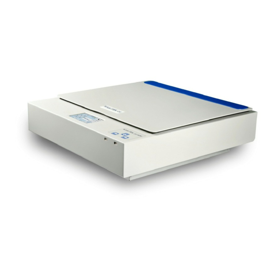
Page 22: Device Overview
Device Overview Picture 6: WideTEK 25-600 front view The main components of the WideTEK 25-600 are: Internal loudspeakers On/off button and status LEDs of the USB connectors. Two USB connectors for storage mediums. Touchscreen B.5.1 Connectors on the Back Picture 7: Connectors on the WideTEK 25-600 backside... -
Page 23: Connecting To The Power Source
After the power source is connected and the main power switch is turned on, the symbol in the on/off button lights up. Red illumination of the on/off button signals that the WideTEK 25-600 is in standby mode. Setup Manual Page 23... -
Page 24: Connecting To The Network
Connecting to the Network Insert the network cable (delivered with the scanner) into the network cable connector (Picture 7, #5). Connect the other side of the cable to a plug-in of an existing network. Alternatively the scanner can be connected directly to a computer with network card by using the crossover cable. -
Page 25: Powering Up The Widetek 25-600
To turn off the WideTEK 25-600 press and hold the on/off button for at least three seconds. While pressing the button, a “click” sound is audible. The content of the touchscreen and the TFT flat screen (if connected) changes and display the message: Going to shut down now …... -
Page 26: Maintenance
Important: Do not use any cleanser with solvents to clean the glass plate! The glass plate of the WideTEK 25-600 has a special non-reflective surface coating. Clean the glass plate with an appropriate glass cleaner and use a soft cloth. -
Page 27: Picture 8: Touchscreen, Kiosk Application
Setup and Adjustment Whenever the WideTEK 25-600 is setup for the first time, moved to a different location, cleaned or serviced and/or after software update; some adjustments have to be performed to guarantee maximum quality and accuracy. Some adjustments can be executed directly via the touchscreen, e.g. the White Balance calibration. -
Page 28: C.1 White Balance
White Balance The white balance function is the most important function for consistent image quality. To ensure optimal performance, the WideTEK 25-600 should be calibrated in regular intervals to compensate for light degradation, variations in the paper quality of the documents to be scanned, and other long term effects. -
Page 29: Picture 10: Setup Menu, Start Screen
C.1.1.1 Executing the White Balance Adjustment The first menu item of the setup menus is the White Balance screen. Picture 10: Setup menu, start screen The touchscreen shows how to position the reference target for the calibration. The reference target is delivered with the scanner. Place the white balance test target at the upper margin of the glass plate. -
Page 30: Picture 12: Content Of Ip Address Menu
IP Address Picture 12: Content of IP Address menu To change or define the numeric values which make up an IP address, touch the number in the respective line of IP address, gateway or netmask. Touch the desired position in the respective row to move the cursor to that position. To delete a digit, place the cursor right beside of the digit and press the “<=”... -
Page 31: Picture 13: User Settings Menu
User Settings Picture 13: User Settings menu The User Settings menu allows defining the touchscreen menu parameters. Language selector The currently selected language is displayed. The touchscreen menu language can be selected by touching the selection arrow. A list opens, showing the available languages. -
Page 32: Picture 14: Selectable Presets
C.3.1 Change GUI Picture 14: Selectable presets The Change GUI menu shows all predefined settings (presets). By default, the presets Easy and Expert are defined. Selecting App Selection switches the touchscreen to the system start screen. Here the user can select between the Scan2Net Kiosk application and App Selection screen. The App Selection screen shows the presets and the apps which are available on the scanner. -
Page 33: Picture 16: Time And Date Screen
Time and Date Picture 16: Time and Date screen To change the time or date value, touch the value in the respective row. Touch the desired position in the respective row to move the cursor to that position. To delete a digit, place the cursor right beside of the digit and press the “<=” button. It will always be deleted from right to left. -
Page 34: Picture 17: User Preset Screen
User Preset Picture 17: User Preset screen By default, two presets are defined. Easy Contains only the basic elements of the kiosk application. This preset only allows modifying a few parameters. Expert Contains all elements of the kiosk application and allows control over all scanner parameters. -
Page 35: C.5.1.1 Activating A Function In The Menus
Configure Touch this button to define the elements that will be displayed with the preset in the kiosk application. The touchscreen changes from the setup menu to the kiosk application. The status section on the right side of the kiosk application shows the message: Configure GUI C.5.1.1 Activating a function in the menus Select a menu from the menu list on top of the touchscreen. -
Page 36: C.5.1.2 Saving The Functions Of The Preset
Selecting functions with the extension (a) will select automatically between button, controller or list when the function is displayed at the touchscreen. Functions with the extension (b) will always display a button at the touchscreen. Touch Ready to save the selected function. Touch Cancel to abort. -
Page 37: Picture 18: Start Screen
Poweruser Level To enter the Poweruser level, start your browser and enter the IP address of the scanner. Picture 18: Start screen The start screen shows three symbols, which lead to the main categories of the Scan2Net user interface. Launch Scan Application changes to the main screen of the scanner interface. Setup Device changes to the setup menu. -
Page 38: Picture 19: Login Level Screen
Setup Menu The Setup screen shows three buttons to select the login level. The access to the levels Poweruser and Admin are password protected. The button Launch Scan Application starts the Scan2Net scan application. The button Back returns to the former screen. Picture 19: Login level screen D.1.1 Selecting the Login Level... -
Page 39: D.1.1.1 Navigating Through The Menus
D.1.1.1 Navigating through the menus The bottom line of each screen shows two buttons at the right side: Setup Menu Returns to the login screen. Launch Scan Application Switches to the main screen of the integrated Scan2Net user interface In each selection menu screen below the parameter to be set, the following button is displayed: Back to Main Menu Returns to the Poweruser main menu (Picture 20). -
Page 40: Picture 20: Poweruser Main Menu
Poweruser Login Level For the following setup steps choose the login level Poweruser . Default user name and default password for this login level are "Poweruser". Note: Please consider that both the user name as well as the password is written with case-sensitive letters. -
Page 41: D.3 Base Settings
Base Settings Base Settings section contains the basic parameters of the scanner. D.3.1 User Settings Please notice: The description of the User Settings can be found in the operation manual, chapter The Setup Screen. The number of parameters in the User Settings section is extended in the Poweruser level by two parameters. -
Page 42: Picture 21: Display Parameters
ICC profile. Picture 21: Display parameters If an external monitor is connected to the WideTEK 25-600 scanner, the matching resolution for the monitor can be selected from a list. To change the resolution, click the selection arrow in the line Display Resolution. -
Page 43: Picture 22: Show Warnings Selector
D.3.1.2 Show Warnings Use the function Show Warnings to set warning messages on or off in the Scan2Net user interface. Picture 22: Show Warnings selector If Yes is selected, warning messages will be displayed if an error occurs. If No is selected, the warnings messages will be suppressed. Setup Manual Page 43... -
Page 44: Picture 23: Ip Configuration Method
D.3.2 Network Configuration The section Network Configuration is divided in nine subsections. The Network Configuration start screen is the IPv4 (Network Interface 0) screen, which is described in chapter D.3.2.2. The following description starts with the IP Configuration Method screen. D.3.2.1 IP Configuration Method The function... -
Page 45: Picture 24: Settings Of Ipv4 (Network Interface 0)
D.3.2.2 IPv4 (Network Interface 0) The function IPv4 (Network Interface 0) allows the operator modifying the parameters for the “Network Interface 0”. This is the primary network and is used for communication with external network devices. Picture 24: Settings of IPv4 (Network Interface 0) The screen shows the parameters for “Network Interface 0”. -
Page 46: Picture 25: Settings Of Ipv4 (Network Interface 1)
D.3.2.3 IPv4 (Network Interface 1) The function IPv4 (Network Interface 1) allows the operator modifying the parameters for the “Network Interface 1”. This is the secondary network and used for communication with internal network devices, e.g. the WLAN module. Picture 25: Settings of IPv4 (Network Interface 1) The screen shows the parameters for the “Network Interface 1”. - Page 47 D.3.2.3.1 Solving a routing conflict in a network As said before, the “Network Interface 0” is used for the communication with external networks; “Network Interface 1” is used for the internal communication with the WLAN module. If the scanner should be operated in an existing network that is configured in the IP address range 10.0.0.x/24 or 10.0.x.x/16 and a host with the IP address 10.0.0.1 is used in this network, a routing conflict will occur.
-
Page 48: Picture 26: Domain Name Server Parameters
D.3.2.4 Domain Name Server This section defines the parameters for the Domain Name Server. Picture 26: Domain Name Server parameters Domain Name Enter the domain name here. Primary DNS Server Enter the address of the primary DNS server here. Secondary DNS Server Enter the address of the secondary DNS server here. -
Page 49: Picture 27: Smb Settings
D.3.2.5 SMB Settings This section defines the parameters for the Settings. Picture 27: SMB Settings Note: The default settings are recommended. SMB Hostname Enter an SMB host name to identify the scanner in the network. Default is the MAC address of the scanner. SMB Workgroup Enter the SMB workgroup in which the scanner is installed. -
Page 50: Picture 28: Wireless Lan Basic Settings
D.3.2.6 Wireless LAN (Basic Settings) Use the function Wireless LAN (Basic Settings) to define the basic settings for the WLAN module. Note: This menu is displayed only if a WLAN module is installed and if the settings for IPv4 (Network Interface 1) Wireless LAN (LAN Interface) fit together. -
Page 51: Picture 29: Wireless Lan (Lan Interface)
D.3.2.7 Wireless LAN (LAN Interface) Use the function Wireless LAN (LAN Interface) to define the network parameter for the Wireless LAN module. Note: This menu is displayed only if a WLAN module is installed and if the settings IPv4 (Network Interface 1) Wireless LAN (LAN Interface) together. -
Page 52: Picture 30: Wireless Lan (Security)
D.3.2.8 Wireless LAN (Security) Use the function Wireless LAN (Security) to define the parameters for wireless LAN security. Note: This menu is displayed only if a WLAN module is installed and if the settings IPv4 (Network Interface 1) Wireless LAN (LAN Interface) together. -
Page 53: Picture 31: Wireless Lan (Dhcp)
D.3.2.9 Wireless LAN (DHCP) Use the function Wireless LAN (DHCP) to define the range of IP addresses that can be used by the WLAN module for DHCP access. Note: This menu is displayed only if a WLAN module is installed and if the settings IPv4 (Network Interface 1) Wireless LAN (LAN Interface) together. -
Page 54: D.3.3 Adjust Time & Date
D.3.3 Adjust Time & Date The section Adjust Time & Date is divided into four subsections. The Adjust Time & Date start screen is the Manual Adjustment screen. The following description starts with the Time Format screen. To set the time correctly for the scanner, execute the adjustments in the following order. Select the time zone. -
Page 55: Picture 32: Time Format
D.3.3.1 Time Format The time shown in the headline of the Scan2Net user interface can be displayed in either 12h or 24h format. Picture 32: Time Format Click on the selection arrow and select the desired time format. The differences between 12h and 24h format are shown below. -
Page 56: Picture 33: Time Zone Screen
D.3.3.2 Time Zone Use the function Time Zone to define the time zone for the internal clock of the scanner. Picture 33: Time Zone screen Click on the selection arrow. A list opens. Select the desired time zone from the list. The list will close and the selected setting is effective immediately. -
Page 57: Picture 35: Ntp Server Setting
D.3.3.4 NTP Server Use the function NTP Server to define the address of time server. Picture 35: NTP Server setting To connect to a NTP server, the scanner must have a connection to the internet. Ask your network administrator for special information concerning your local network. Enter the address of the NTP server in the line NTP server. -
Page 58: Picture 36: Set Volume
D.3.4 Sound System The section Sound System is divided into three subsections. The Sound System start screen is the Set Volume screen. D.3.4.1 Set Volume Use the function Set Volume to set the loudspeakers volume of the scanner. Picture 36: Set Volume A screen opens and shows a graphic to symbolize the volume. -
Page 59: Picture 37: Sound Files List
D.3.4.2 Sound Files Use the function Sound Files to list the sounds which are linked to system events. Picture 37: Sound Files list Scroll to the bottom of the list to search and upload new sounds to the scanner. Picture 38: Upload new sound files Click on the button Search to search the directories of your local PC and/or your network for sound files. -
Page 60: Picture 39: Link Events List
D.3.4.3 Link Events Use the function Link Events to change the sounds linked to system events. Picture 39: Link Events list The list of links contains thirteen events. The sound file that is listed at each event is dependent on the language set for the scanner . -
Page 61: Picture 40: Options List
To activate an option, a unique key must be entered. The key is valid only with one specific scanner and cannot be transferred to another scanner. The software keys can be purchased at the Image Access Customer Service Portal. Visit the URL portal.imageaccess.de... -
Page 62: Picture 41: Update Scanner Firmware
D.4.1 Update Scanner Firmware Upload a new firmware version to the scanner. Picture 41: Update Scanner Firmware The Image Access Customer Service Portal (CSP) at portal.imageaccess.de offers firmware updates for every Scan2Net scanner. In order to download the appropriate firmware version update for your scanner, you must be a registered user. Log in to the CSP with your personal login name and password. - Page 63 In the screen Update Scanner Firmware (see Picture 41) click on the selection arrow beside “Post update behavior” of the scanner from the list. Select Reboot from the list. This will start the scanner automatically after the firmware update sequence is completed. Browse your local PC and select the previously downloaded firmware update file.
-
Page 64: Picture 42: Scanner Profile
D.4.2 ICC Profiles section Profiles divided into subsections Scanner Profile, Monitor Profiles, and Printer Profiles. ICC profiles are integrated in the image file data. First of all, download the respective ICC profile for the device to your local PC. D.4.2.1 Scanner Profile The ICC profile loaded at Scanner Profile adapts the color space between scanner and image editing software. -
Page 65: Picture 43: Icc Profile Installed
Picture 43: ICC Profile installed To delete the ICC profile, click on the “Delete” symbol. To get information about the ICC profile, click on the information symbol Picture 44: ICC Profile information Setup Manual Page 65... -
Page 66: Picture 45: Monitor Profiles
D.4.2.2 Monitor Profiles The ICC profile will be adapted to the image data displayed at the external monitor of the Bookeye 4 scanner. Select Monitor Profiles to upload an ICC profile for the external monitor. Picture 45: Monitor Profiles Click on the “Delete” symbol to delete the ICC profile. Click the button to search the directories of your local PC and/or your Search network for ICC profile files. -
Page 67: Picture 46: Icc Profile Information
Click on the information symbol to get information about the ICC profile. Picture 46: ICC Profile information D.4.2.2.2 Activating the ICC profile To activate the ICC profile for the external monitor, select the menu Viewer & Job Control in the touchscreen and mark the checkbox for the ICC Profile. Picture 47: Touchscreen menu, ICC profile selected Setup Manual Page 67... -
Page 68: Picture 48: Printer Profiles
D.4.2.3 Printer Profiles The ICC profiles for printers adapt the color space of the scanner to the color space of the printer used with the scanner. Select Printer Profiles to upload an ICC printer profile. Picture 48: Printer Profiles Click the button to search the directories of your local PC and/or your Search network for ICC profile files. -
Page 69: Picture 50: Printer Profile Information
To get information about the ICC profile, click on the information symbol in the line of the ICC profile. Picture 50: Printer profile information D.4.2.3.1 Selecting the ICC profile to be used In the S2N user interface of the scanner click on the link Options below the button Copy. -
Page 70: D.4.3 Touchscreen / Desktop
D.4.3 Touchscreen / Desktop These functions are temporarily not available. Page 70 Setup Manual... -
Page 71: Picture 51: Java Apps
D.4.4 Java Apps This section enables installing and selecting Java applications for special user-defined tasks. Picture 51: Java Apps The installed Java Apps are listed on the screen. To delete a Java App from the list, click on the “Delete” symbol at the right side of the line. -
Page 72: Picture 52: Adjustment Start Screen
Adjustments & Support D.5.1 Adjustments The Adjustment screen shows the links to the optical adjustments. Picture 52: Adjustment start screen The optical adjustment of the WideTEK 25-600 contains one menu item: The section White Balance Adjustments contains two buttons. White Balance... -
Page 73: Picture 53: White Balance Start Screen
White Balance The white balance function is the most important function for consistent image quality. To ensure optimal performance, the WideTEK 25-600 should be calibrated in regular intervals to compensate light degradation, variations in the paper quality of the documents to be scanned, and other long term effects. -
Page 74: Picture 54: White Balance Results
After completing the measurement, the screen shows the results. Picture 54: White Balance results Note: It is normal that the measurement will return different values each time the measurement is repeated. The lens motor has a very high resolution and the best focal point has to be found in the already large focal range, therefore a variation of 50 –... -
Page 75: Picture 55: Brightness Correction
D.5.1.2 Brightness Correction The brightness correction function does not perform any measurements; it only allows setting a correction factor for the brightness. The interval of the correction factor is ± 2 dB. Picture 55: Brightness Correction Click on the selection arrow. The list of the available values will be displayed. -
Page 76: Picture 56: Log Files Overview
D.5.2 Log Files D.5.2.1 Show Log Files While working with the scanner, the activities will be logged in several log files. Picture 56: Log files overview Log file Content FTP Log FTP transfers will be logged with all transfer data. SMTP Log SMTP transfers will be logged with all transfer data. -
Page 77: Picture 57: Log File Content
The log file is a ZIP archive and contains information to analyze the stitching algorithm. It is password protected and cannot be opened by the user. In case of an error the ZIP archive should be sent to the Image Access support. It will help to analyze the error and to find a solution. -
Page 78: Picture 58: Available Test Target
D.5.3 Scan Test Targets For system analysis and troubleshooting, three test targets can be used. The CSTT test target and the IT8 test target included with the scanner. D.5.3.1 Scan CSTT Test Target Click on the respective button to select the CSTT test target for the scan sequence. Picture 58: Available test target The next screen shows the position of the CSTT test target at the glass plate. -
Page 79: Picture 60: Request After Scanning The Test Target
Place two CSTT test targets on the glass plate as shown at the screen. Click on the Next Step button to start scanning the test targets. The test sequence will take approximately 30 seconds. After scanning, the image will not be displayed. A small window –... -
Page 80: Picture 61: Utt Test Target On Glass Plate
D.5.3.2 Scan UTT Test Target Click on the respective button to select the UTT test target for the scan sequence. Note: The UTT test target is not included with the scanner. Picture 61: UTT test target on glass plate The procedure is the same as described with the CSTT test target. The resulting image differs in the name because of the other test target. -
Page 81: Picture 63: Network Analyzer Start Screen
D.5.4 Network Analyzer This menu allows to test the network performance and to view the packet statistics. Picture 63: Network analyzer start screen D.5.4.1 Perform Speed Test Click on Perform Speed Test to check the date transfer speed. Picture 64: Network Analyzing Parameters Target Address Enter an IP address which can be accessed from the scanner to test the data transfer speed. -
Page 82: Picture 65: Measured Time
The result of the measurement is displayed at the next screen. Picture 65: Measured Time The bar graphic shows the three values: Minimum The fastest transfer time between the scanner and the target address. Average The average time for all transferred packets. Maximum The maximum transfer time during the test. -
Page 83: Picture 67: Wake Up Remote Host
Administrative Settings D.6.1 Wake up Remote Host If an external PC is used with the scanner, it can be helpful to start the PC at the same time when the scanner starts. This can be automatized by activating the Wake up Remote Host function. Picture 67: Wake up Remote Host The requirements for using this function: In the BIOS of the external PC the function “Wake on LAN”... -
Page 84: Picture 68: Change Password Menu
D.6.2 Change Password It is recommended to modify the password often, to protect the limited access to the Poweruser level. Click on Change Password . Picture 68: Change password menu Select Level Click on the selection arrow to open the list of log-in levels. Select the log-in level, for which the password should be changed. -
Page 85: Picture 69: Small Window At Bottom Line With Inquiry For Action
D.6.3 Backup Settings To store the current settings of the scanner, a ZIP archive file can be created. Click on Backup Setting to create the ZIP archive. Depending on the browser used, a small window opens at the bottom line of the current window or a separate window opens. -
Page 86: Picture 70: Restore Setting From Zip File
D.6.4 Restore Settings With this function, the ZIP file stored with the “Backup Settings” function can be loaded to the scanner. Click on Restore Settings . Picture 70: Restore setting from ZIP file To find the ZIP archive, click on Search and browse the directory structure to find the desired ZIP archive file. -
Page 87: Picture 72: Enter Password To Lock The Scan2Net User Interface
D.6.5 Lock Web App This function locks the Scan2Net user interface. When the Scan2Net user interface is locked, the scanner can only be controlled by the touchscreen or by external software. Important: The user interface can only be unlocked from the Administrator level. Picture 72: Enter password to lock the Scan2Net user interface New Password Enter the new password. -
Page 88: D.7 Resets & Default Values
Resets & Default Values D.7.1 Set Scanner Defaults This function enables saving settings for color mode, resolution, document mode as well as network parameters and other parameters. When powering up, the scanner starts with the saved settings. To modify the settings, switch to the Scan2Net user interface and set all parameters to the desired values. -
Page 89: Picture 73: Recovery Key
Troubleshooting Disconnect the power cable before doing any maintenance to the device. Recovery Function The recovery function helps to set all device parameters to factory defaults after a fatal system breakdown. The recovery key is necessary to invoke the recovery procedure. A recovery key is delivered with every device;... -
Page 90: Picture 74: Connectors On The Widetek 25
E.1.2 How to Recover to Factory Defaults Important: The scanner must be in stand-by mode before inserting the recovery key. 1. Main power switch 2. Network cable connector 3. External power supply connector 4. Foot pedal connector 5. Serial port / Recovery key connector 6. - Page 91 • Change the network parameters to the values which were used before running the recovery sequence. Select Setup Device Poweruser . Locate the section Base Settings and click the button Network Configuration . Enter the values for the IP address, the subnet mask, and the default gateway as described in chapter D.3.2 Network Configuration and its sub-chapters.
-
Page 92: E.2 Troubleshooting
Troubleshooting Fields with a light blue background need the power user access level. All other fields are available to all users. Problem Possible cause Action Image is darker than The test target, which is Go to the White Balance function. expected. -
Page 93: E.3 Error Codes And Warnings
Error Codes and Warnings The scanner does report error conditions on the display and through the API. Some errors are only sent to the API. A green problem description signals that operation of the scanner is still possible although the error will have an influence on the behavior or quality of the scanner. A problem description in red marks an errors which will stop the scanner and inhibits further scanning. - Page 94 Error codes, part 2 Error # Error message shown in Error message sent to Problem description the display application File format not supported. The specified file format is not supported or it is invalid in combination with the color mode. Preview not possible The application specified an invalid preview scale.
-
Page 95: E.3.2 Warnings
Error codes, part 3 Error # Error message shown in Error message sent to Problem description the display application Error 70: Camera 2 adc error. Test data transfer through analog ADC error camera 2 digital converter failed. Check cables / connectors to camera 2. General keyboard error General keyboard error. -
Page 96: F Technical Data
Technical Data Scanner Specifications Optical System Maximum document width 25 x 18.5 inches / 635 x 470 mm Optical / interpolated resolution 1200 x 600 dpi / 1200 x 1200 dpi Camera type Two tricolor CCDs, encapsulated and dust- proof Color depth 12 bit grayscale (internal resolution) 36 bit color (internal resolution) -
Page 97: F.3 Electrical Specifications
Electrical Specifications External Power Supply Voltage 100 – 240 V AC Frequency 47 – 63 Hz Inrush current 120 A max / 264 V AC Efficiency 87 % Operating temperature 0 to 65 °C / 32 to 149 °F Operating humidity 10 to 93 % RH, non-condensing ECO standard CEC level V... -
Page 98: F.5 Ce Declaration Of Conformity
Image Access GmbH Hatzfelder Strasse 161 – 163 42281 Wuppertal, Germany herewith declares that the Product: WideTEK 25-600 Scanner Model Designation: WT25 –XXX XXX represents the device version number and configuration details) Serial number: is in conformity with the following European standards and IEC directives:... - Page 99 EMC: Directive 2004/108/EEC Class A: EN 55022:2010 EN 61000-3-2:2006 + A1:2009 + A2:2009 EN 61000-3-3:2008 EN 55024:2010 EN 61000-4-2:2009 EN 61000-4-3:2006 + A1:2008 + A2:2010 EN 61000-4-4:2004 + A1:2010 EN 61000-4-5:2006 EN 61000-4-6:2009 EN 61000-4-11:2004 Wuppertal, April 2012 Thomas Ingendoh , President and CEO Setup Manual Page 99...
-
Page 100: F.6 Fcc Declaration Of Conformity
FCC Declaration of Conformity Responsible party: Image Access GmbH Hatzfelderstrasse 161 – 163 42281 Wuppertal, Germany Product: WideTEK 25-600 Model Designation: WT25 –XXX XXX represents the device version number and configuration details) Serial number: This device complies with FCC 47, Part 15, Class A and ICES-003, Class A. - Page 101 For your notes Setup Manual Page 101...
Need help?
Do you have a question about the WideTEK 25-600 and is the answer not in the manual?
Questions and answers