
Related Manuals for Enterasys B5G124-24


Summary of Contents for Enterasys B5G124-24
- Page 1 Enterasys ® Gigabit Ethernet Switch Hardware Installation Guide B5G124-24, B5G124-24P2 B5G124-48, B5G124-48P2 B5K125-24, B5K125-24P2 B5K125-48, B5K125-48P2 P/N 9034527-02...
- Page 3 Elektrischer Gefahrenhinweis: Installationen sollten nur durch ausgebildetes und qualifiziertes Personal vorgenommen werden. Notice Enterasys Networks reserves the right to make changes in specifications and other information contained in this document and its web site without prior notice. The reader should in all cases consult Enterasys Networks to determine whether any such changes have been made. The hardware, firmware, or software described in this document is subject to change without notice. IN NO EVENT SHALL ENTERASYS NETWORKS BE LIABLE FOR ANY INCIDENTAL, INDIRECT, SPECIAL, OR CONSEQUENTIAL DAMAGES WHATSOEVER (INCLUDING BUT NOT LIMITED TO LOST PROFITS) ARISING OUT OF OR RELATED TO THIS DOCUMENT, WEB SITE, OR THE INFORMATION CONTAINED IN THEM, EVEN IF ENTERASYS NETWORKS HAS BEEN ADVISED OF, KNEW OF, OR SHOULD HAVE KNOWN OF, THE POSSIBILITY OF SUCH DAMAGES. Enterasys Networks, Inc. 50 Minuteman Road Andover, MA 01810 © 2010 Enterasys Networks, Inc. All rights reserved. Part Number: 9034527‐02 August 2010 ENTERASYS, ENTERASYS NETWORKS, ENTERASYS SECURE NETWORKS, NETSIGHT, ENTERASYS NETSIGHT, and any logos associated therewith, are trademarks or registered trademarks of Enterasys Networks, Inc., in the United States and/or other countries. For a complete list of Enterasys trademarks, see http://www.enterasys.com/company/trademarks.aspx. All other product names mentioned in this manual may be trademarks or registered trademarks of their respective companies. Documentation URL: http://www.enterasys.com/support/manuals Documentacion URL: http://www.enterasys.com/support/manuals Dokumentation im Internet: http://www.enterasys.com/support/manuals...
-
Page 4: Regulatory Compliance Information
Regulatory Compliance Information Federal Communications Commission (FCC) Notice This device complies with Part 15 of the FCC rules. Operation is subject to the following two conditions: (1) this device may not cause harmful interference, and (2) this device must accept any interference received, including interference that may cause undesired operation. NOTE: This equipment has been tested and found to comply with the limits for a class A digital device, pursuant to Part 15 of the FCC rules. These limits are designed to provide reasonable protection against harmful interference when the equipment is operated in a commercial environment. This equipment uses, generates, and can radiate radio frequency energy and if not installed in accordance with the operator’s manual, may cause harmful interference to radio communications. Operation of this equipment in a residential area is likely to cause interference in which case the user will be required to correct the interference at his own expense. WARNING: Changes or modifications made to this device which are not expressly approved by the party responsible for compliance could void the user’s authority to operate the equipment. Industry Canada Notice This digital apparatus does not exceed the class A limits for radio noise emissions from digital apparatus set out in the Radio Interference Regulations of the Canadian Department of Communications. Le présent appareil numérique n’émet pas de bruits radioélectriques dépassant les limites applicables aux appareils numériques de la class A prescrites dans le Règlement sur le brouillage radioélectrique édicté par le ministère des Communications du Canada. Class A ITE Notice WARNING: This is a Class A product. In a domestic environment this product may cause radio interference in which case the user may be required to take adequate measures. Clase A. Aviso de ITE ADVERTENCIA: Este es un producto de Clase A. En un ambiente doméstico este producto puede causar interferencia de radio ... -
Page 5: Hazardous Substances
In accordance with Directive 2002/96/EC of the European Parliament on waste electrical and electronic equipment (WEEE): The symbol above indicates that separate collection of electrical and electronic equipment is required and that this product was placed on the European market after August 13, 2005, the date of enforcement for Directive 2002/96/EC. When this product has reached the end of its serviceable life, it cannot be disposed of as unsorted municipal waste. It must be collected and treated separately. It has been determined by the European Parliament that there are potential negative effects on the environment and human health as a result of the presence of hazardous substances in electrical and electronic equipment. It is the users’ responsibility to utilize the available collection system to ensure WEEE is properly treated. For information about the available collection system, please go to www.enterasys.com/services/support/ or contact Enterasys Customer Support at 353 61 705586 (Ireland). Battery Notice This product contains a battery used to maintain product information. If the battery should need replacement it must be replaced by Service Personnel. Please contact Technical Support for assistance. Caution: There is an explosion risk if you replace the battery with the incorrect type. Dispose of expended battery in accordance with local disposal regulations. - Page 6 SJ/T 11363-2006 standard. This table shows where these substances may be found in the supply chain of Enterasys’ electronic information products, as of the date of sale of the enclosed product. Note that some of the component types listed above may or may not be a part of the enclosed product.
-
Page 7: Safety Information
Safety Information Class 1 Laser Transceivers The single mode interface modules use Class 1 laser transceivers. Read the following safety information before installing or operating these modules. The Class 1 laser transceivers use an optical feedback loop to maintain Class 1 operation limits. This control loop eliminates the need for maintenance checks or adjustments. The output is factory set, and does not allow any user adjustment. Class 1 Laser transceivers comply with the following safety standards: • 21 CFR 1040.10 and 1040.11 U.S. Department of Health and Human Services (FDA). • IEC Publication 825 (International Electrotechnical Commission). • CENELEC EN 60825 (European Committee for Electrotechnical Standardization). When operating within their performance limitations, laser transceiver output meets the Class 1 accessible emission limit of all three standards. Class 1 levels of laser radiation are not considered hazardous. When the connector is in place, all laser radiation remains within the fiber. The maximum amount of radiant power exiting the ‐6 fiber (under normal conditions) is ‐12.6 dBm or 55 x 10 watts. -
Page 8: Declaration Of Conformity
Declaration of Conformity Application of Council Directive(s): 2004/108/EC 2006/95/EC Manufacturer’s Name: Enterasys Networks, Inc. Manufacturer’s Address: 50 Minuteman Road Andover, MA 01810 European Representative Name: Enterasys Networks, Ltd. European Representative Address: Nexus House, Newbury Business Park London Road, Newbury Berkshire RG14 2PZ, England Conformance to Directive(s)/Product Standards: EC Directive 2004/108/EC EN 55022:2006 EN 55024:1998 EN 61000‐3‐2:2006 EN 61000‐3‐3:1995 EC Directive 2006/95/EC EN 60950‐1:2006 EN 60825‐1:2007 EN 60825‐2:2004 Equipment Type/Environment: Information Technology Equipment, for use in a Commercial or Light Industrial Environment. Enterasys Networks, Inc. declares that the equipment packaged with this notice conforms to the above directives. - Page 9 Enterasys Networks, Inc. Firmware License Agreement BEFORE OPENING OR UTILIZING THE ENCLOSED PRODUCT, CAREFULLY READ THIS LICENSE AGREEMENT. This document is an agreement (“Agreement”) between the end user (“You”) and Enterasys Networks, Inc., on behalf of itself and its Affiliates (as hereinafter defined) (“Enterasys”) that sets forth Your rights and obligations with respect to the Enterasys software program/firmware (including any accompanying documentation, hardware or media) (“Program”) in the package and prevails over any additional, conflicting or inconsistent terms and conditions appearing on any purchase order or other document submitted by You. “Affiliate” means any person, partnership, corporation, limited liability company, other form of enterprise that directly or indirectly through one or more intermediaries, controls, or is controlled by, or is under common control with the party specified. This Agreement constitutes the entire understanding between the parties, with respect to the subject matter of this Agreement. The Program may be contained in firmware, chips or other media. BY INSTALLING OR OTHERWISE USING THE PROGRAM, YOU REPRESENT THAT YOU ARE AUTHORIZED TO ACCEPT THESE TERMS ON BEHALF OF THE END USER (IF THE END USER IS AN ENTITY ON WHOSE BEHALF YOU ARE AUTHORIZED TO ACT, “YOU” AND “YOUR” SHALL BE DEEMED TO REFER TO SUCH ENTITY) AND THAT YOU AGREE THAT YOU ARE BOUND BY THE TERMS OF THIS AGREEMENT, WHICH INCLUDES, AMONG OTHER PROVISIONS, THE LICENSE, THE DISCLAIMER OF WARRANTY AND THE LIMITATION OF LIABILITY. IF YOU DO NOT AGREE TO THE TERMS OF THIS AGREEMENT OR ARE NOT AUTHORIZED TO ENTER INTO THIS AGREEMENT, ENTERASYS IS UNWILLING TO LICENSE THE PROGRAM TO YOU AND YOU AGREE TO RETURN THE UNOPENED PRODUCT TO ENTERASYS OR YOUR DEALER, IF ANY, WITHIN TEN (10) DAYS FOLLOWING THE DATE OF RECEIPT FOR A FULL REFUND. IF YOU HAVE ANY QUESTIONS ABOUT THIS AGREEMENT, CONTACT ENTERASYS NETWORKS, LEGAL DEPARTMENT AT (978) 684‐1000. You and Enterasys agree as follows: LICENSE. You have the non‐exclusive and non‐transferable right to use only the one (1) copy of the Program provided in ...
- Page 10 CONTRACT, TORT OR OTHERWISE, SHALL NOT EXCEED THE TOTAL AMOUNT OF FEES PAID TO ENTERASYS BY YOU FOR THE RIGHTS GRANTED HEREIN. AUDIT RIGHTS. You hereby acknowledge that the intellectual property rights associated with the Program are of critical value to Enterasys, and, accordingly, You hereby agree to maintain complete books, records and accounts showing (i) license fees due and paid, and (ii) the use, copying and deployment of the Program. You also grant to Enterasys and its authorized representatives, upon reasonable notice, the right to audit and examine during Your normal business hours, Your books, records, accounts and hardware devices upon which the Program may be deployed to verify compliance with this Agreement, including the verification of the license fees due and paid Enterasys and the use, copying and deployment of the Program. Enterasys’ right of examination shall be exercised reasonably, in good faith and in a manner calculated to not unreasonably interfere with Your business. In the event such audit discovers non‐compliance with this Agreement, including copies of the Program made, used or deployed in breach of this Agreement, You shall promptly pay to Enterasys the appropriate license fees. Enterasys reserves the right, to be exercised in its sole discretion and without prior notice, to terminate this license, effective immediately, for failure to comply with this Agreement. Upon any such termination, You shall immediately cease all use of the Program and shall return to Enterasys the Program and all copies of the Program. OWNERSHIP. This is a license agreement and not an agreement for sale. You acknowledge and agree that the Program constitutes trade secrets and/or copyrighted material of Enterasys and/or its suppliers. You agree to implement reasonable security measures to protect such trade secrets and copyrighted material. All right, title and interest in and to the Program shall remain with Enterasys and/or its suppliers. All rights not specifically granted to You shall be reserved to Enterasys. 10. ENFORCEMENT. You acknowledge and agree that any breach of Sections 2, 4, or 9 of this Agreement by You may cause Enterasys irreparable damage for which recovery of money damages would be inadequate, and that Enterasys may be entitled to seek timely injunctive relief to protect Enterasys’ rights under this Agreement in addition to any and all remedies available at law. 11. ASSIGNMENT. You may not assign, transfer or sublicense this Agreement or any of Your rights or obligations under this Agreement, except that You may assign this Agreement to any person or entity which acquires substantially all of Your stock assets. Enterasys may assign this Agreement in its sole discretion. This Agreement shall be binding upon and inure to the benefit of the parties, their legal representatives, permitted transferees, successors and assigns as permitted by this Agreement. Any attempted assignment, transfer or sublicense in violation of the terms of this Agreement shall be void and a breach of this Agreement. 12. WAIVER. A waiver by Enterasys of a breach of any of the terms and conditions of this Agreement must be in writing and will not be construed as a waiver of any subsequent breach of such term or condition. Enterasys’ failure to enforce a term upon Your breach of such term shall not be construed as a waiver of Your breach or prevent enforcement on any other occasion. viii...
- Page 11 13. SEVERABILITY. In the event any provision of this Agreement is found to be invalid, illegal or unenforceable, the validity, legality and enforceability of any of the remaining provisions shall not in any way be affected or impaired thereby, and that provision shall be reformed, construed and enforced to the maximum extent permissible. Any such invalidity, illegality, or unenforceability in any jurisdiction shall not invalidate or render illegal or unenforceable such provision in any other jurisdiction. 14. TERMINATION. Enterasys may terminate this Agreement immediately upon Your breach of any of the terms and conditions of this Agreement. Upon any such termination, You shall immediately cease all use of the Program and shall return to Enterasys the Program and all copies of the Program.
-
Page 13: Table Of Contents
Contents About This Guide Who Should Use This Guide ..........................xv How to Use This Guide .............................xv Related Documents ............................xvi Conventions Used in This Guide ........................xvi Getting Help ..............................xvii Chapter 1: Introduction Overview ................................. 1-1 Features ................................. 1-5 High-Speed Stack Connections ....................... - Page 14 Pluggable Transceiver Specifications ......................A-9 Console Port Pinout Assignments ........................A-9 Regulatory Compliance ..........................A-9 Figures B5G124-24 and B5G124-24P2 Front Panel..................1-2 B5G124-48 and B5G124-48P2 Front Panel..................1-3 B5K125-24 and B5K125-24P2 Front Panel..................1-3 B5K125-48 and B5K125-48P2 Front Panel..................1-3 B5 Switch Back Panels (Non-PoE B5 Switches) ................1-4 B5 Switch Back Panels (PoE B5 Switches)..................
- Page 15 Installing an SFP/10G Transceiver (shown with LC connector and without dust cover) ....2-28 2-20 Cable Connection (LC shown) to Uplink Port with SFP/10G Installed ..........2-30 B5G124-24 and B5G124-24P2 LEDs....................3-2 B5K125-24 and B5K125-24P2 LEDs ....................3-2 B5G124-48 and B5G124-48P2 LEDs....................3-3 B5K125-48 and B5K125-48P2 LEDs ....................
-
Page 17: About This Guide
Troubleshooting installation problems and diagnosing Chapter 3, Troubleshooting network/operational problems using the LEDs Specifications, environmental requirements, and physical Appendix A, Specifications properties of the B5 and optional pluggable transceivers Enterasys B5 Gigabit Ethernet Switch Hardware Installation Guide xv... -
Page 18: Related Documents
Related Documents Related Documents The following manual can be obtained from the World Wide Web in Adobe Acrobat Portable Document Format (PDF) at the following site: http://www.enterasys.com/support/manuals Enterasys B5 CLI Reference describes how to use the Command Line Interface (CLI) to set up and manage the switches. Conventions Used in This Guide The following conventions are used in this guide: Note: Calls the reader’s attention to any item of information that may be of special importance. Caution: Contains information essential to avoid damage to the equipment. -
Page 19: Getting Help
World Wide Web www.enterasys.com/services/support/ Phone 1-800-872-8440 (toll-free in U.S. and Canada) or 1-978-684-1888 For the Enterasys Networks Support toll-free number in your country: www.enterasys.com/services/support/contact/ Email support@enterasys.com To expedite your message, please type [B-Series] in the subject line. To send comments or suggestions concerning this document to the Technical Publications Department: techpubs@enterasys.com... - Page 20 Getting Help xviii About This Guide...
-
Page 21: Chapter 1: Introduction
(see Figure 1-2 on page 1-3) • Four combo SFP ports B5G124-48P2 • 48 10/100/1000Base-T 802.3af and (see Figure 1-2 on page 1-3) 802.3at PoE-capable ports • Four combo SFP ports Enterasys B5 Gigabit Ethernet Switch Hardware Installation Guide 1-1... -
Page 22: B5G124-24 And B5G124-24P2 Front Panel
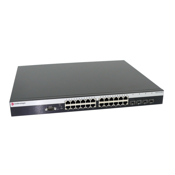
SFP interfaces. When an SFP transceiver in SFP port 23 establishes a link, RJ45 port 23 is disabled. When an SFP transceiver in SFP port 24 establishes a link, RJ45 port 24 is disabled. Figure 1-1 B5G124-24 and B5G124-24P2 Front Panel Switch status LEDs RJ45 port status LEDs... -
Page 23: B5G124-48 And B5G124-48P2 Front Panel
Figure 1-4 B5K125-48 and B5K125-48P2 Front Panel Switch status LEDs RJ45 port status LEDs RJ45 10/100/1000 Mbps ports SFP port status LEDs SFP slots 10G port status LEDs 10G slots Console port Enterasys B5 Gigabit Ethernet Switch Hardware Installation Guide 1-3... -
Page 24: B5 Switch Back Panels (Non-Poe B5 Switches)
Overview Figure 1‐5 and Figure 1‐6 show the back panels of the B5 switches. Figure 1-5 B5 Switch Back Panels (Non-PoE B5 Switches) Stack connection ports (shown without covers) AC power input connector Rotary switch Redundant power supply (RPS) connector (shown without cover) Password reset button Figure 1-6 B5 Switch Back Panels (PoE B5 Switches) Stack connection ports (shown without covers) AC power input connector Rotary switch... -
Page 25: Features
• STK‐RPS‐500PS, a 500 watt DC power supply for redundant power for PoE B5 switches. If the internal power supply fails, the RPS assumes the entire load of the switch without interrupting network traffic. The internal power supply and RPS each have their own AC power connection, which enables the connection of each power supply to a different AC power circuit for additional AC power source redundancy. Rotary Switch Currently, the rotary switch is for future use only. PoE (Power over Ethernet) Support The B5 PoE‐capable models (B5G124‐24P2, B5G124‐48P2, B5K125‐24P2, and B5K125‐48P2) are IEEE 802.3af and 802.3at compliant, which means they can provide power over Ethernet (PoE) cable connections from their RJ45 connectors to PDs in the network. PoE, defined in IEEE standards 802.3af and 802.3at, refers to the ability to provide 54 Vdc (for 802.3at) or 48 Vdc (for 802.3af) operational power through an Ethernet cable from a switch or other device that can provide a PoE‐compliant port connection to a powered device (PD). Examples of PDs include: • Voice over IP devices such as PoE‐compliant digital telephones • Devices that support Wireless Application Protocol (WAP) such as wireless access points • Security cameras • Virtual desktops The B5 PoE‐capable models support the standard resistor‐based detection method, as well as AC disconnect capability. Enterasys B5 Gigabit Ethernet Switch Hardware Installation Guide 1-5... -
Page 26: Number Of B5 Ports Providing Poe Power Simultaneously
PoE (Power over Ethernet) Support Table 1‐2 lists, for each B5 PoE‐compliant model, the number of ports that can provide 802.3af and 802.3at PoE power. Table 1-2 Number of B5 Ports Providing PoE Power Simultaneously Ports Providing PoE Power Simultaneously B5 Model 802.3af 802.3at (30W) B5G124-24P2 24 ports (15.4W) 12 ports B5K125-24P2 24 ports (15.4W) 12 ports B5G124-48P2 24 ports (15.4W), 48 ports (7.5W) 12 ports... -
Page 27: Considerations Prior To Installation
Installing and Connecting B5 Redundant Power Systems 2-11 Connecting to the Console Port for Local Management 2-22 Connecting to the Network 2-25 Completing the Installation 2-30 Considerations Prior to Installation When installing the switch, note the following: • Before starting the installation procedure, notify the network administrator of the installation. • Follow the installation procedures in the order as presented in this guide. • Do not connect the switch to the network until you have established the correct IP address. Enterasys B5 Gigabit Ethernet Switch Hardware Installation Guide 2-1... -
Page 28: Required Tools
Rubber feet with adhesive backing for installation on a flat surface AC power cord (The type of power cord is country dependent.) DB9 female-to-DB9 female Console Cable Quick Start Guide Remove the tape seal on the non‐conductive bag to remove the switch. Perform a visual inspection of the switch for any signs of physical damage. Contact Enterasys Networks if there are any signs of damage. Refer to “Getting Help” on page xvii for details. Installing the Switch on a Flat Surface When installing the switch on a flat surface, the installation of the rubber feet is recommended to prevent the switch from sliding on a flat surface. For instructions to rack mount the switch, proceed to “Rack Mounting the Switch” on page 2‐4. -
Page 29: Guidelines For Flat Surface Installation
5.1 cm (2 pulgadas) con respecto a los lados y a la parte posterior del aparato. No conecte el dipositivo a la fuente primaria hasta que no se le indique. Enterasys B5 Gigabit Ethernet Switch Hardware Installation Guide 2-3... -
Page 30: Rack Mounting The Switch
Rack Mounting the Switch If you are installing several switches in a stack, proceed to “Connecting High‐Speed Stacking Cables” on page 2‐6. If the switch is being installed as a standalone switch, proceed to “Connecting AC Power” on page 2‐10 for power connection instructions. Figure 2-2 Area Guidelines for Switch Installation on Flat Surface 1 Approximately 152 cm (5 ft) from power source 3 44.5 cm (19.4 in.) for proper ventilation 2 4.45 cm (1.75 in.) per switch. (Vertical clearance 4 41.9 cm (16.5 in.) for proper ventilation depends on number of switches stacked.) Rack Mounting the Switch... -
Page 31: Attaching The Brackets And Installing In A Rack
Note: Do not install the rubber feet if you are rack mounting the switch. Attaching the Brackets and Installing in a Rack Proceed as follows to install the switch into a 19‐inch rack: Attach the rackmount brackets to the switch, as shown in Figure 2‐3, using the eight M3x6 mm flathead screws shipped with the switch. Figure 2-3 Attaching the Rackmount Brackets 1 Rackmount brackets 2 M3x6 mm flathead screws With the mounting brackets attached, position the switch between the vertical frame members of the 19‐inch rack as shown in Figure 2‐4. Then fasten the switch securely to the frame using four customer‐supplied mounting screws. Enterasys B5 Gigabit Ethernet Switch Hardware Installation Guide 2-5... -
Page 32: Connecting High-Speed Stacking Cables
Connecting High-Speed Stacking Cables Figure 2-4 Fastening the Switch to the Rack 1 Rails of 19-inch rack 2 Mounting screws If you are installing this switch in a stacked configuration, repeat this procedure for each switch until all switches have been installed in the stack, then proceed to “Connecting High‐ Speed Stacking Cables” on page 2‐6. Otherwise, proceed to “Connecting AC Power” on page 2‐10. Connecting High-Speed Stacking Cables Note: By default, the stack connection ports are covered with removable covers. If you are not connecting stacking cables, keep the covers on the stack connection ports. -
Page 33: High-Speed Stacking Cable Connections
5 STACK UP connector at bottom of stack 3 STACK UP connector Note: Hand tighten the screws on the stacking cables to ensure good connections to the STACK DOWN and STACK UP connectors. After connecting the cables to the stacking ports, proceed to “Configuring Switches in a Stack” on page 2‐8 for instructions. Enterasys B5 Gigabit Ethernet Switch Hardware Installation Guide 2-7... -
Page 34: Configuring Switches In A Stack
Configuring Switches in a Stack Configuring Switches in a Stack The information in the following sections is important to understand B5 switch operation and installations in a stack installation. About B5 Switch Operation in a Stack The B5 switches are stackable switches that can be adapted and scaled to help meet your network needs. These switches provide a management platform and uplink to a network backbone for a stacked group of up to eight B5 switches. Note: You can stack a B5 switch only with other B5 switches. You cannot stack a B5 switch with swtiches that are not B5 switches. -
Page 35: Stack Manager Selection
(regardless of priority, firmware revision, or MAC address). The switches are assigned unit IDs in the order that you power on each switch. Note: Once switch IDs are assigned, they are persistent and will be retained during a power cycle to any or all of the switches. Connect to Console port of the manager switch. (Optional) If desired, change the management switch using the set switch movemanagement command as described in the Enterasys B5 CLI Reference. Once the desired master switch has been selected, reset the system using the reset command as described in the Enterasys B5 CLI Reference. Enterasys B5 Gigabit Ethernet Switch Hardware Installation Guide 2-9... -
Page 36: Adding A New Switch To An Existing Stack
Apply power to the new switch. Important Considerations About Using Clear Config in a Stack When using the clear config command (as described in the Enterasys B5 CLI Reference) to clear configuration parameters in a stack, it is important to remember the following: • Use clear config to clear config parameters without clearing stack switch IDs. This command WILL NOT clear stack parameters and avoids the process of re-numbering the stack. -
Page 37: Installing And Connecting B5 Redundant Power Systems
Help” on page xvii for details If the switch is a standalone switch, it will take approximately 30 seconds for the switch to start up. If the switch is a stack manager, it can take up to 3 minutes or more to start up, depending on the number of member switches in the stack. Installing and Connecting B5 Redundant Power Systems Depending on your B5 switch, you can install one of the following redundant power supplies: • STK‐RPS‐150PS, a 150W redundant power supply for non‐PoE B5 models. • STK‐RPS‐500PS, a 500W redundant power supply for PoE‐compliant B5 models. STK-RPS-150PS You can install an STK‐RPS‐150PS in the following RPS shelves: • STK‐RPS‐150CH2, a two‐slot chassis • STK‐RPS‐150CH8, an eight‐slot chassis Required Tools A flat‐blade screwdriver is required to install the STK‐RPS‐150CH2 or STK‐RPS‐150CH8 shelf and STK‐RPS‐150PS power supplies. Enterasys B5 Gigabit Ethernet Switch Hardware Installation Guide 2-11... -
Page 38: Unpacking The Shelf And Power Supply
Installing and Connecting B5 Redundant Power Systems Unpacking the Shelf and Power Supply The shelf and the power supply are shipped separately. To unpack these devices proceed as follows: Open the box and remove the packing material protecting the shelf or power supply. Verify the contents of each carton and compare the contents shipped with those listed in Table 2‐1, Table 2‐2, and Table 2‐3. Perform a visual inspection of the switch devices for any signs of physical damage. Contact Enterasys Networks if there are any signs of damage. Refer to “Getting Help” on page xvii for details. Table 2-1 Contents of STK-RPS-150CH2 Carton Item Quantity STK-RPS-150CH2 Quick Reference Release Notes Table 2-2 Contents of STK-RPS-150CH8 Carton... -
Page 39: Stk-Rps-150Ps Installation In An Stk-Rps-150Ch2 Shelf
Installing and Connecting B5 Redundant Power Systems Fasten the power supply to the chassis using the captive screws on the PSM front panel. Repeat steps 2 and 3 for each additional power supply. Proceed to “Installing the Shelf into the Rack” on page 2‐15 for the rack mount installation instructions. Figure 2-7 STK-RPS-150PS Installation in an STK-RPS-150CH2 Shelf 1 STK-RPS-150CH2 shelf 3 Shelf power supply slot 2 STK-RPS-150PS power supply 4 Captive screws (2) Enterasys B5 Gigabit Ethernet Switch Hardware Installation Guide 2-13... -
Page 40: Removing An Installed Stk-Rps-150Ps
Installing and Connecting B5 Redundant Power Systems Figure 2-8 STK-RPS-150PS Installation in an STK-RPS-150CH8 Shelf 1 STK-RPS-150CH8 shelf 3 Captive screws (2) 2 STK-RPS-150PS power supply 4 Chassis power supply slot Removing an Installed STK-RPS-150PS To remove a power supply installed in an operating system, proceed as follows: Caution: Observe all Electrostatic Discharge (ESD) precautions when handling sensitive electronic equipment. -
Page 41: Installing The Shelf Into The Rack
De otra forma puede suceder algun tipo de daño personal o del equipo. Warnhinweis: Schützen Sie sich vor Verletzungen und Geräteschaden, überzeugen Sie sich vor der Installation des Chassis in das Rack, von dessen Stabilität. Enterasys B5 Gigabit Ethernet Switch Hardware Installation Guide 2-15... -
Page 42: Fastening The Stk-Rps-150Ch2 To The Rack
Installing and Connecting B5 Redundant Power Systems Rack Mounting the Chassis Refer to Figure 2‐9 or Figure 2‐10 and proceed as follows to install the chassis into a 19‐inch (48.3‐ cm) rack: Position the chassis between the vertical rails and align the mounting holes in the chassis brackets with those in the rack frame. Fasten the chassis securely to the rails using the customer‐supplied mounting screws (four for the STK‐RPS‐150CH2, ten for the STK‐RPS‐150CH8). Figure 2-9 Fastening the STK-RPS-150CH2 to the Rack 1 STK-RPS-150CH2 chassis 3 Mounting screws 2 Rails of 19-inch rack 2-16 Installation... -
Page 43: Connecting The Rps Cable And Ac Power Cord
Connecting the RPS Cable and AC Power Cord The redundant power supply is connected to a B5 Ethernet switch switch using an RPS cable. To connect a redundant power supply, proceed as follows: Using a Philips screwdriver, remove the cover from the redundant power supply connector on the B5 switch. Connect one end of the RPS cable to the redundant power supply connector on the B5 switch. Then connect the other end of the cable to the redundant power supply connector at the rear of the RPS as shown in Figure 2‐11. Connect the AC power cord to the AC input power connector on the RPS shown in Figure 2‐12, then plug the AC power cord into the main AC power outlet. The green Power LED on the front of the RPS will illuminate to indicate a successful connection. If the LED remains off, proceed as follows: Check the AC power cord connection at the AC power source and make sure the power source is within specification. b. Check the AC power connection to the RPS. Swap the AC power cord with a known good one. d. If the green LED continues to remain off, contact Enterasys Networks. Refer to “Getting Help” on page xvii for instructions. Otherwise, proceed to step 4. Enterasys B5 Gigabit Ethernet Switch Hardware Installation Guide 2-17... -
Page 44: Power Connectors On Stk-Rps-150Ps (Rear View)
Installing and Connecting B5 Redundant Power Systems On certain switches, an LED indicator will show that a redundant power supply is now in operation. Note: No change in switch configuration is necessary for this installation. Figure 2-11 Power Connectors on STK-RPS-150PS (rear view) Redundant power supply connector AC power connector Figure 2-12 STK-RPS-150PS RPS Cable and AC Power Cord Connections B5 switch B5 switch redundant power supply connector RPS cable... -
Page 45: Stk-Rps-500Ps
STK-RPS-500PS (front view) STK-RPS-500PS (rear view) LED status indicator Air vents for cooling Redundant Power Supply connector AC power input connector The STK‐RPS‐500PS is shipped with the following: • AC power cord • RPS cable • Four rubber feet (for flat surface installation) • Two rack mount brackets • Eight flathead screws (M3x6) Enterasys B5 Gigabit Ethernet Switch Hardware Installation Guide 2-19... -
Page 46: Installing The Stk-Rps-500Ps
Installing and Connecting B5 Redundant Power Systems Installing the STK-RPS-500PS You can install the STK‐RPS‐500PS on a flat surface or in a 19‐inch rack. Locate the STK‐RPS‐500PS within 152 cm (5 ft) of its power source. Rack Mounting the STK-RPS-500PS To install the STK‐RPS‐500PS in a 19‐inch rack, you need: • Two rackmount brackets and mounting screws (rackmount kit) shipped with the STK‐RPS‐500PS. • Four customer‐supplied screws to attach the STK‐RPS‐500PS to a standard 19‐inch rack. To install an STK‐RPS‐500PS in the shelf: Attach the rackmount brackets to the STK‐RPS‐500PS, as shown in Figure 2‐14, using the eight M3 x 6 mm flathead screws shipped with the STK‐RPS‐500PS. Figure 2-14 Attaching the Rackmount Brackets Rackmount brackets (2) M3 x 6 mm flathead screws (8) 2-20 Installation... -
Page 47: Connecting The Rps Cable And Ac Power Cord
Installing the STK-RPS-500PS on a Flat Surface When installing the STK‐RPS‐500PS on a flat surface, the installation of the rubber feet is recommended to prevent the STK‐RPS‐500PS from sliding on a flat surface. To install the rubber feet: Place the STK‐RPS‐500PS on its back on a sturdy flat surface to gain access to the bottom of the chassis. Remove the four rubber feet from their plastic bag in the shipping box. Locate the four marked locations on the bottom four corners of the STK‐RPS‐500PS. Remove the protective strip from the back of one rubber foot and position it on a marked location and press firmly into place. Repeat this procedure to install the remaining three rubber feet. After installing the rubber feet, return the STK‐RPS‐500PS to its upright position. Connecting the RPS Cable and AC Power Cord The STK‐RPS‐500PS is connected to the B5 PoE switch using the RPS cable, as follows: Turn off the B5 switch and unplug it from the power source before installing the STK‐RPS‐ 500PS. The B5 switch does not support hot insertion/removal of an RPS cable. If you hot insert an RPS cable into a running B5 switch, the B5 switch will not recognize that an RPS cable is installed and the B5 switch will lose power if the primary power supply fails. Enterasys B5 Gigabit Ethernet Switch Hardware Installation Guide 2-21... -
Page 48: Connecting To The Console Port For Local Management
Connecting to the Console Port for Local Management Connect one end of the RPS cable to the redundant power supply connector on the B5 switch. Then connect the other end to the redundant power supply connector at the rear of the STK‐ RPS‐500PS as shown in Figure 2‐16. Figure 2-16 STK-RPS-500PS RPS Cable and AC Power Cord Connections B5 switch AC power cord (type varies depending on country) RPS cable AC power outlet with ground connection (type varies depending on country) STK-RPS-500PS output connector B5 redundant power supply connector... -
Page 49: What Is Needed
DB9 Male Console Port Pinout Assignments Pin 2, Received Data (input) Pin 3, Transmitted Data (output) Pin 5, Signal Ground Pin 7, Request to Send Pin 8, Clear to Send All other pins not connected. Enterasys B5 Gigabit Ethernet Switch Hardware Installation Guide 2-23... -
Page 50: Connecting To A Pc
Connecting to the Console Port for Local Management Connecting to a PC To connect a PC, running the VT terminal emulation, to a B5 Console port: Connect the DB9 female connector at one end of the cable (supplied with switch) to the Console port on the B5 switch. (If there is a switch designated as the manager, connect to its Console port.) Plug the DB9 female connector at the other end of cable into the communications port on the Turn on the PC and configure your VT emulation package with the following parameters: Parameter Setting Mode 7 Bit Control Transmit Transmit=9600 Bits Parity 8 Bits, No Parity Stop Bit 1 Stop Bit When these parameters are set, the Startup screen will display. Proceed to “Connecting to the Network” on page 2‐25. Connecting to a VT Series Terminal To connect a VT Series terminal to an B5 Console port, use a UTP serial interface cable terminated ... -
Page 51: Connecting To A Modem
Transmit Transmit=9600 Bits Parity 8 Bits, No Parity Stop Bit 1 Stop Bit When these parameters are set, the Startup screen will display. If the switches are in a stacked configuration, proceed to “Connecting to the Network” on page 2‐25. Connecting to the Network The following procedures cover the cable connections from the network or other devices to the B5 switch front panel ports. • “Connecting UTP Cables to RJ45 Ports” on page 2‐26 • “Installing an Optional SFP/10G Transceiver” on page 2‐27 • “Connecting Fiber‐Optic Cables to SFP/10G Ports” on page 2‐29 Enterasys B5 Gigabit Ethernet Switch Hardware Installation Guide 2-25... -
Page 52: Connecting Utp Cables To Rj45 Ports
10 Mbps. To connect twisted pair segments to the switch, refer to Figure 2‐18 and proceed as follows: Ensure that the device to be connected at the other end of the segment is powered on. Connect the twisted pair segment to the switch by inserting the RJ45 connector on the twisted pair segment into the desired RJ45 port on the B5 switch. Figure 2-18 Connecting a UTP Cable Segment to an RJ45 Port Verify that a link exists by checking that the Link/Activity LED is on (solid green or blinking green). If the Link/Activity LED is off, perform the following steps until it is on: Verify that the cabling being used is Category 5 or better with an impedance between 85 and 111 ohms with a maximum length of 100 meters (328 feet). b. Verify that the device at the other end of the twisted pair segment is on and properly connected to the segment. Verify that the RJ45 connectors on the twisted pair segment have the proper pinouts and check the cable for continuity. If a link is not established, contact Enterasys Networks. Refer to “Getting Help” on page xvii for details. Repeat all steps above until all connections have been made. 2-26 Installation... -
Page 53: Preparing To Install An Optional Sfp/10G Transceiver
Hilfsmittel, um die Funktion des Lasers zu überprüfen. Solche Hilfsmittel erhöhen die Gefahr von Sehschäden. Wenn sie den optischen Port überprüfen möchten stellen Sie sicher, dass die Komponente von der Spannungsversorgung getrennt ist. Enterasys B5 Gigabit Ethernet Switch Hardware Installation Guide 2-27... -
Page 54: Installing An Sfp/10G Transceiver (Shown With Lc Connector And Without Dust Cover)
Connecting to the Network Caution: Carefully follow the instructions in this manual to avoid damaging the SFP/10G and switch equipment. The SFP/10G and switch equipment are sensitive to static discharges. Use an antistatic wrist strap and observe all static precautions during this procedure. Failure to do so could result in damage to the SFP/10G and switch equipment. -
Page 55: Removing An Sfp/10G Transceiver
Si nota que losextremos de los cables de fibra óptica se ensucian, utilice aire comprimido paralimpiarlos. También puede limpiarlos con un estropajo embebido en alcohol isopropílico. Enterasys B5 Gigabit Ethernet Switch Hardware Installation Guide 2-29... -
Page 56: Completing The Installation
Completing the Installation Refer to Figure 2‐20 as you perform the following procedure. To connect an LC or MT‐RJ cable connector to an SFP or 10G port connector: Remove the protective covers (not shown) from the uplink port SFP/10G and from the connectors on each end of the cable. Note: Leave the protective covers in place when the connectors are not in use to prevent contamination. Insert the cable connector into the connector until it clicks into place. SFP/10G Figure 2-20 Cable Connection (LC shown) to Uplink Port with SFP/10G Installed Combo SFP port with transceiver installed 2 LC cable connector Release tab... - Page 57 Completing the Installation For details on how to configure the switch using the command line interface, refer to the Enterasys B5 CLI Reference. The CLI commands enable you to set a new password and perform more involved management configurations on the switch. One of many capabilities is to reconfigure the stack, reassigning the Manager function to another switch and configuring the order of Member switches that will take over the stack management functions in case the operating Manager is powered down, malfunctions, or is removed from the stack. After the initial configuration, you can also use WebView (Enterasys Networks’ embedded web server) for configuration and management tasks. All the guides associated with the switch are available online at: http://www.enterasys.com/support/manuals Once you are confident that the installation is successful, route and secure your cables. If you require assistance, contact Enterasys Networks using one of the methods described in “Getting Help” on page xvii. Enterasys B5 Gigabit Ethernet Switch Hardware Installation Guide 2-31...
- Page 58 Completing the Installation 2-32 Installation...
-
Page 59: Chapter 3: Troubleshooting
Warnhinweis: Ist der Stromkreis in Betrieb dürfen keine Verbindungen getrennt oder hergestellt werden, es sei denn, die Umgebung gilt als ungefährlich. Alle externen Verbindungen zu diesem Gerät müssen mithilfe von Schrauben, Sicherheitsvorrichtungen o. ä. gesichert werden. Enterasys B5 Gigabit Ethernet Switch Hardware Installation Guide 3-1... -
Page 60: Checking The Leds
Checking the LEDs Checking the LEDs The following sections define the behavior of the LEDs on the B5 chassis models. Refer to Figure 3‐1, Figure 3‐2, Figure 3‐3, and Figure 3‐4 for the location of the LEDs on the chassis. Figure 3-1 B5G124-24 and B5G124-24P2 LEDs 1 CPU LED 5 MGR LED 2 STACK DOWN LED 6 Link/Activity/PoE LEDs for 10/100/1000 Mbps for 3 STACK UP LED RJ45 ports 1 through 24... -
Page 61: B5G124-48 And B5G124-48P2 Leds
SFP port 47 is linked, RJ45 port 47 is deactivated. When the SFP is not linked, the RJ45 port 47 is reactivated and can establish a link as long as the SFP port 47 is not linked first.) Enterasys B5 Gigabit Ethernet Switch Hardware Installation Guide 3-3... -
Page 62: Mgr Led
4. Ensure the DC power cord from the RPS to the switch is plugged in correctly. 5. If the problem persists, contact Enterasys Networks for technical support. Amber Solid. The switch internal power supply None. failed, and the RPS is providing the proper power to the switch. -
Page 63: Up Led
3. If the problem still exists, contact Enterasys Networks for technical support. Green Solid. Valid connection to switch stack up None. connector. Blinking. Information is being transferred None. through the high-speed stacking cable. Enterasys B5 Gigabit Ethernet Switch Hardware Installation Guide 3-5... -
Page 64: Cpu Led
3. If the switch still does not power up, the system may have a fatal error. Contact Enterasys Networks for technical support. Solid. Boot-up failed. If the LED remains red for several minutes, the system may have a fatal error. Contact Enterasys Networks for technical support. -
Page 65: Rj45 Poe Port Led Definitions
Green Solid. Port is linked, but the interface is None. not receiving any traffic. Blinking. Port is linked and traffic is being None. received or transmitted by the interface. Enterasys B5 Gigabit Ethernet Switch Hardware Installation Guide 3-7... -
Page 66: Troubleshooting Checklist
If the problem continues, contact Enterasys Networks for technical support. Port(s) goes into Loop condition detected. Verify that Spanning Tree is enabled. Refer to the Enterasys B5 CLI standby for no Reference for the instructions to set the type of STA. apparent reason. -
Page 67: Using The Password Reset Button
In order to unlock the admin user account, you can wait for the configured lockout time to expire or you can power cycle the switch to reboot it. Removing the Switch from a Rack To remove the B5 switch from a rack: While supporting the switch so it does not fall, carefully remove the mounting screws from the two brackets that attach the switch to the rack. If necessary, remove each bracket from the switch by removing the mounting kit screws as shown in Figure 2‐3 on page 2‐5. Enterasys B5 Gigabit Ethernet Switch Hardware Installation Guide 3-9... - Page 68 Removing the Switch from a Rack 3-10 Troubleshooting...
-
Page 69: Appendix A: Specifications
B5G124-48 and B5G124-48P2 Forty-eight 10BASE-T/100BASE-TX/1000BASE-T compliant RJ45 ports 1 through 48 ports with auto-sensing and auto-negotiation via RJ45 connectors. These ports also support 802.3at and 802.3af PoE connections on the B5G124-48P2. Enterasys B5 Gigabit Ethernet Switch Hardware Installation Guide A-1... - Page 70 Switch Specifications Table A-1 B5 Switch Specifications (continued) Item Specification Combo SFP ports 47 through 50 Four ports that support optional pluggable transceiver 100BASE-FX, 1000BASE-SX, 1000BASE-LX, and 1000BASE-TX fiber-optic connections. When an SFP transceiver in SFP port 47 establishes a link, RJ45 port 47 is disabled.
- Page 71 Table A-1 B5 Switch Specifications (continued) Item Specification Performance Throughput capacity wirespeed Mpps • B5G124-24 — 35.7 Mpps / 85.7 Mpps (switch/stack) • B5G124-24P2 — 35.7 Mpps / 85.7 Mpps • B5G124-48 — 71.4 Mpps /571.4 Mpps • B5G124-48P2 — 71.4 Mpps /571.4 Mpps •...
- Page 72 Power Specifications Input Voltage 100 to 240 VAC Power Consumption • B5G124-24 — 63W (214 BTU/hr) • B5G124-24P2 — 130W (444 BTU/hr) • B5G124-48 — 76W (258 BTU/hr) • B5G124-48P2 — 225W (768 BTU/hr) • B5K125-24 — 59W (200 BTU/hr) •...
-
Page 73: Rps Specifications
47–63 Hz AC Input Voltage Range 85–264 Vac Output Voltage 12 Vdc Output Current 1.0 A min., 8.5 A or 13.0 A max. Maximum Output Power 102 W or 156 W continuous Enterasys B5 Gigabit Ethernet Switch Hardware Installation Guide A-5... -
Page 74: Stk-Rps-500Ps Specifications
RPS Specifications Table A-4 STK-RPS-150PS Specifications (continued) Item Specification Physical Dimensions 19.6 H x 5.2 W x 25.7 D (cm) 7.7 H x 2.04 W x 10.1 D (in.) Net Weight (Unit Only) 1.75 kg (3.85 lb) Gross Weight (Packaged Unit) 3.20 kg (7.04 lb) MTBF 300,000 Hours... -
Page 75: Stk-Rps-150Ps Redundant Power Supply Connector
Pin Number Function Ground Ground No connection No connection 12 Vdc Output No connection 12 Vdc Output Status 1 12 Vdc Output Status 2 12 Vdc Output Power good Ground Ground Enterasys B5 Gigabit Ethernet Switch Hardware Installation Guide A-7... -
Page 76: Stk-Rps-500Ps Redundant Power Supply Connector
RPS Specifications STK-RPS-500PS Redundant Power Supply Connector For pin location and function, refer to Figure A‐2 and Table A‐7, respectively. Note: The following information is for troubleshooting purposes only. For proper operation, use only the RPS cable supplied with the STK-RPS-500PS. This cable is specially designed for this application and meets all necessary Regulatory and Safety standards. The use of non-approved cables will void your warranty. -
Page 77: Torque Values
(Class A), EN 55024, EN 61000-3-2, EN 61000-3-3, AS/NZ CISPR-22 (Class A). VCCI V-3. CNS 13438 (BSMI), 2004/108/EC (EMC Directive) Environmental 2002/95/EC (RoHS Directive), 2002/96/EC (WEEE Directive), Ministry of Information Order #39 (China RoHS) Enterasys B5 Gigabit Ethernet Switch Hardware Installation Guide A-9... - Page 78 Regulatory Compliance A-10 Specifications...
Need help?
Do you have a question about the B5G124-24 and is the answer not in the manual?
Questions and answers