
Related Manuals for Enterasys Enterasys SecureStack B2 B2G124-24


Summary of Contents for Enterasys Enterasys SecureStack B2 B2G124-24
- Page 1 Enterasys SecureStack ® ™ Gigabit and Fast Ethernet Switches Hardware Installation Guide B2G124-24 B2G124-48 B2H124-48 P/N 9034099-05...
- Page 3 Elektrischer Gefahrenhinweis: Installationen sollten nur durch ausgebildetes und qualifiziertes Personal vorgenommen werden. Enterasys Networks reserves the right to make changes in specifications and other information contained in this document and its web site without prior notice. The reader should in all cases consult Enterasys Networks to determine whether any such changes have been made. The hardware, firmware, or software described in this document is subject to change without notice. IN NO EVENT SHALL ENTERASYS NETWORKS BE LIABLE FOR ANY INCIDENTAL, INDIRECT, SPECIAL, OR CONSEQUENTIAL DAMAGES WHATSOEVER (INCLUDING BUT NOT LIMITED TO LOST PROFITS) ARISING OUT OF OR RELATED TO THIS DOCUMENT, WEB SITE, OR THE INFORMATION CONTAINED IN THEM, EVEN IF ENTERASYS NETWORKS HAS BEEN ADVISED OF, KNEW OF, OR SHOULD HAVE KNOWN OF, THE POSSIBILITY OF SUCH DAMAGES. Enterasys Networks, Inc. 50 Minuteman Road Andover, MA 01810 © 2008 Enterasys Networks, Inc. All rights reserved. Part Number: 9034099‐05 February 2008 ENTERASYS, ENTERASYS NETWORKS, ENTERASYS MATRIX, ENTERASYS SECURESTACK, LANVIEW, NETSIGHT, WEBVIEW, and any logos associated therewith, are trademarks or registered trademarks of Enterasys Networks, Inc., in the United States and other countries. All other product names mentioned in this manual may be trademarks or registered trademarks of their respective companies. Documentation URL: http://www.enterasys.com/support/manuals Documentacion URL: http://www.enterasys.com/support/manuals...
-
Page 4: Regulatory Compliance Information
REGULATORY COMPLIANCE INFORMATION FEDERAL COMMUNICATIONS COMMISSION (FCC) NOTICE This device complies with Part 15 of the FCC rules. Operation is subject to the following two conditions: (1) this device may not cause harmful interference, and (2) this device must accept any interference received, including interference that may cause undesired operation. NOTE: This equipment has been tested and found to comply with the limits for a class A digital device, pursuant to Part 15 of the FCC rules. These limits are designed to provide reasonable protection against harmful interference when the equipment is operated in a commercial environment. This equipment uses, generates, and can radiate radio frequency energy and if not installed in accordance with the operator’s manual, may cause harmful interference to radio communications. Operation of this equipment in a residential area is likely to cause interference in which case the user will be required to correct the interference at his own expense. WARNING: Changes or modifications made to this device which are not expressly approved by the party responsible for compliance could void the user’s authority to operate the equipment. This digital apparatus does not exceed the class A limits for radio noise emissions from digital apparatus set out in the Radio Interference Regulations of the Canadian Department of Communications. Le présent appareil numérique n’émet pas de bruits radioélectriques dépassant les limites applicables aux appareils numériques de la class A prescrites dans le Règlement sur le brouillage radioélectrique édicté par le ministère des Communications du Canada. WARNING: This is a Class A product. In a domestic environment this product may cause radio interference in which case the user may be required to take adequate measures. ADVERTENCIA: Este es un producto de Clase A. En un ambiente doméstico este producto puede causar interferencia de radio en cuyo caso puede ser requerido tomar medidas adecuadas. WARNHINWEIS: Dieses Produkt zählt zur Klasse A ( Industriebereich ). In Wohnbereichen kann es hierdurch zu Funkstörungen kommen, daher sollten angemessene Vorkehrungen zum Schutz getroffen werden. This product complies with the following: UL 60950, CSA C22.2 No. 60950, 73/23/EEC, EN 60950, IEC 60950, EN 60825, 21 CFR 1040.10. El producto de Enterasys cumple con lo siguiente: UL 60950, CSA C22.2 No. 60950, 73/23/EEC, EN 60950, IEC 60950, EN 60825, 21 CFR 1040.10. - Page 5 This product complies with the following: 47 CFR Parts 2 and 15, CSA C108.8, 89/336/EEC, EN 55022, EN 61000‐3‐2, EN 61000‐3‐3, EN 55024, AS/NZS CISPR 22, VCCI V‐3. COMPATIBILIDAD ELECTROMÁGNETICA (EMC) Este producto de Enterasys cumple con lo siguiente: 47 CFR Partes 2 y 15, CSA C108.8, 89/336/EEC, EN 55022, EN 55024, EN 61000‐3‐2, EN 61000‐3‐3, AS/NZS CISPR 22, VCCI V‐3. ELEKTRO- MAGNETISCHE KOMPATIBILITÄT ( EMC ) Dieses Produkt entspricht den folgenden Richtlinien: 47 CFR Parts 2 and 15, CSA C108.8, 89/336/EEC, EN 55022, EN 61000‐3‐2, EN 61000‐3‐3, EN 55024, AS/NZS CISPR 22, VCCI V‐3. This product complies with the requirements of European Directive, 2002/95/EC, Restriction of Hazardous Substances (RoHS) in Electrical and Electronic Equipment. EUROPEAN WASTE ELECTRICAL AND ELECTRONIC EQUIPMENT (WEEE) NOTICE In accordance with Directive 2002/96/EC of the European Parliament on waste electrical and electronic equipment (WEEE): The symbol above indicates that separate collection of electrical and electronic equipment is required and that this product was placed on the European market after August 13, 2005, the date of enforcement for Directive 2002/96/EC. When this product has reached the end of its serviceable life, it cannot be disposed of as unsorted municipal waste. It must be collected and treated separately. It has been determined by the European Parliament that there are potential negative effects on the environment and human health as a result of the presence of hazardous substances in electrical and electronic equipment. It is the users’ responsibility to utilize the available collection system to ensure WEEE is properly treated. For information about the available collection system, please go to http://www.enterasys.com/services/support/ or contact Enterasys Customer Support at 353 61 705586 (Ireland). ELECTROMAGNETIC COMPATIBILITY (EMC) HAZARDOUS SUBSTANCES...
- Page 6 Supplement to Product Instructions (Parts) (Metal Parts) Circuit Modules) Cables & Cable Assemblies) (Plastic and Polymeric parts) Circuit Breakers) Indicates that the concentration of the hazardous substance in all homogeneous materials in the parts is below the relevant threshold of the SJ/T 11363-2006 standard. Indicates that the concentration of the hazardous substance of at least one of all homogeneous materials in the parts is above the relevant threshold of the SJ/T 11363-2006 standard.
- Page 7 This is a class A product based on the standard of the Voluntary Control Council for Interference by Information Technology Equipment (VCCI). If this equipment is used in a domestic environment, radio disturbance may arise. When such trouble occurs, the user may be required to take corrective actions. This is a class A product. In a domestic environment this product may cause radio interference in which case the user may be required to take adequate measures. SINGLE MODE NETWORK EXPANSION MODULES USE CLASS 1 LASER TRANSCEIVERS. READ THE FOLLOWING SAFETY INFORMATION BEFORE INSTALLING OR OPERATING THESE MODULES. The Class 1 laser transceivers use an optical feedback loop to maintain Class 1 operation limits. This control loop eliminates the need for maintenance checks or adjustments. The output is factory set, and does not allow any user adjustment. Class 1 Laser transceivers comply with the following safety standards: • 21 CFR 1040.10 and 1040.11 U.S. Department of Health and Human Services (FDA). • IEC Publication 825 (International Electrotechnical Commission). • CENELEC EN 60825 (European Committee for Electrotechnical Standardization). When operating within their performance limitations, laser transceiver output meets the Class 1 accessible emission limit of all three standards. Class 1 levels of laser radiation are not considered hazardous. When the connector is in place, all laser radiation remains within the fiber. The maximum amount of radiant power exiting the fiber (under normal conditions) is ‐12.6 dBm or 55 x 10 Removing the optical connector from the transceiver allows laser radiation to emit directly from the optical port. The maximum radiance from the optical port (under worst case conditions) is 0.8 W cm Do not use optical instruments to view the laser output. The use of optical instruments to view laser output increases ...
- Page 8 Application of Council Directive(s): 89/336/EEC Manufacturer’s Address: 50 Minuteman Road European Representative Address: Enterasys Networks, Ltd. Conformance to Directive(s)/Product Standards: EC Directive 89/336/EEC Equipment Type/Environment: Networking Equipment, for use in a Commercial Enterasys Networks, Inc. declares that the equipment packaged with this notice conforms to the above directives. DECLARATION OF CONFORMITY 73/23/EEC Manufacturer’s Name: Enterasys Networks, Inc. Andover, MA 01810 Nexus House, Newbury Business Park London Road, Newbury Berkshire RG14 2PZ, England EN 55022 EN 61000‐3‐2 EN 61000‐3‐3 EN 55024 EC Directive 73/23/EEC EN 60950 EN 60825 or Light Industrial Environment.
-
Page 9: Firmware License Agreement
BEFORE OPENING OR UTILIZING THE ENCLOSED PRODUCT, This document is an agreement (“Agreement”) between the end user (“You”) and Enterasys Networks, Inc. on behalf of itself and its Affiliates (as hereinafter defined) (“Enterasys”) that sets forth Your rights and obligations with respect to the Enterasys software program/firmware installed on the Enterasys product (including any accompanying documentation, hardware or media) (“Program”) in the package and prevails over any additional, conflicting or inconsistent terms and conditions appearing on any purchase order or other document submitted by You. “Affiliate” means any person, partnership, corporation, limited liability company, or other form of enterprise that directly or indirectly through one or more intermediaries, controls, or is controlled by, or is under common control with the party specified. This Agreement constitutes the entire understanding between the parties, and supersedes all prior discussions, representations, understandings or agreements, whether oral or in writing, between the parties with respect to the subject matter of this Agreement. The Program may be contained in firmware, chips or other media. BY INSTALLING OR OTHERWISE USING THE PROGRAM, YOU REPRESENT THAT YOU ARE AUTHORIZED TO ACCEPT THESE TERMS ON BEHALF OF THE END USER (IF THE END USER IS AN ENTITY ON WHOSE BEHALF YOU ARE AUTHORIZED TO ACT, “YOU” AND “YOUR” SHALL BE DEEMED TO REFER TO SUCH ENTITY) AND THAT YOU AGREE THAT YOU ARE BOUND BY THE TERMS OF THIS AGREEMENT, WHICH INCLUDES, AMONG OTHER PROVISIONS, THE LICENSE, THE DISCLAIMER OF WARRANTY AND THE LIMITATION OF LIABILITY. IF YOU DO NOT AGREE TO THE TERMS OF THIS AGREEMENT OR ARE NOT AUTHORIZED TO ENTER INTO THIS AGREEMENT, ENTERASYS IS UNWILLING TO LICENSE THE PROGRAM TO YOU AND YOU AGREE TO RETURN THE UNOPENED PRODUCT TO ENTERASYS OR YOUR DEALER, IF ANY, WITHIN TEN (10) DAYS FOLLOWING THE DATE OF RECEIPT FOR A FULL REFUND. IF YOU HAVE ANY QUESTIONS ABOUT THIS AGREEMENT, CONTACT ENTERASYS NETWORKS, LEGAL DEPARTMENT AT (978) 684‐1000. You and Enterasys agree as follows: LICENSE. You have the non‐exclusive and non‐transferable right to use only the one (1) copy of the Program provided in this package subject to the terms and conditions of this Agreement. RESTRICTIONS. Except as otherwise authorized in writing by Enterasys, You may not, nor may You permit any third party to: (i) Reverse engineer, decompile, disassemble or modify the Program, in whole or in part, including for reasons of error correction or interoperability, except to the extent expressly permitted by applicable law and to the extent the parties shall not be permitted by that applicable law, such rights are expressly excluded. Information necessary to achieve interoperability or correct errors is available from Enterasys upon request and upon payment of Enterasys’ applicable fee. (ii) Incorporate the Program, in whole or in part, in any other product or create derivative works based on the ... - Page 10 APPLICABLE LAW. This Agreement shall be interpreted and governed under the laws and in the state and federal courts of the Commonwealth of Massachusetts without regard to its conflicts of laws provisions. You accept the personal jurisdiction and venue of the Commonwealth of Massachusetts courts. None of the 1980 United Nations Convention on Contracts for the International Sale of Goods, the United Nations Convention on the Limitation Period in the International Sale of Goods, and the Uniform Computer Information Transactions Act shall apply to this Agreement. EXPORT RESTRICTIONS. You understand that Enterasys and its Affiliates are subject to regulation by agencies of the U.S. Government, including the U.S. Department of Commerce, which prohibit export or diversion of certain technical products to certain countries, unless a license to export the Program is obtained from the U.S. Government or an exception from obtaining such license may be relied upon by the exporting party. If the Program is exported from the United States pursuant to the License Exception CIV under the U.S. Export Administration Regulations, You agree that You are a civil end user of the Program and agree that You will use the Program for civil end uses only and not for military purposes. If the Program is exported from the United States pursuant to the License Exception TSR under the U.S. Export Administration Regulations, in addition to the restriction on transfer set forth in Sections 1 or 2 of this Agreement, You agree not to (i) reexport or release the Program, the source code for the Program or technology to a national of a country in Country Groups D:1 or E:2 (Albania, Armenia, Azerbaijan, Belarus, Bulgaria, Cambodia, Cuba, Estonia, Georgia, Iraq, Kazakhstan, Kyrgyzstan, Laos, Latvia, Libya, Lithuania, Moldova, North Korea, the People’s Republic of China, Romania, Russia, Rwanda, Tajikistan, Turkmenistan, Ukraine, Uzbekistan, Vietnam, or such other countries as may be designated by the United States Government), (ii) export to Country Groups D:1 or E:2 (as defined herein) the direct product of the Program or the technology, if such foreign produced direct product is subject to national security controls as identified on the U.S. Commerce Control List, or (iii) if the direct product of the technology is a complete plant or any major component of a plant, export to Country Groups D:1 or E:2 the direct product of the plant or a major component thereof, if such foreign produced direct product is subject to national security controls as identified on the U.S. Commerce Control List or is subject to State Department controls under the U.S. Munitions List. UNITED STATES GOVERNMENT RESTRICTED RIGHTS. The enclosed Program (i) was developed solely at private expense; (ii) contains “restricted computer software” submitted with restricted rights in accordance with section 52.227‐19 (a) through (d) of the Commercial Computer Software‐Restricted Rights Clause and its successors, and (iii) in all respects is proprietary data belonging to Enterasys and/or its suppliers. For Department of Defense units, the Program is considered commercial computer software in accordance with DFARS section 227.7202‐3 and its successors, and use, duplication, or disclosure by the Government is subject to restrictions set forth herein. DISCLAIMER OF WARRANTY. EXCEPT FOR THOSE WARRANTIES EXPRESSLY PROVIDED TO YOU IN WRITING BY ENTERASYS, ENTERASYS DISCLAIMS ALL WARRANTIES, EITHER EXPRESS OR IMPLIED, INCLUDING BUT NOT LIMITED TO IMPLIED WARRANTIES OF MERCHANTABILITY, SATISFACTORY QUALITY, FITNESS FOR A PARTICULAR PURPOSE, TITLE AND NON‐ INFRINGEMENT WITH RESPECT TO THE PROGRAM. IF IMPLIED WARRANTIES MAY NOT BE DISCLAIMED BY APPLICABLE LAW, THEN ANY IMPLIED WARRANTIES ARE LIMITED IN DURATION TO THIRTY (30) DAYS AFTER DELIVERY OF THE PROGRAM TO ...
- Page 11 AUDIT RIGHTS. You hereby acknowledge that the intellectual property rights associated with the Program are of critical value to Enterasys and, accordingly, You hereby agree to maintain complete books, records and accounts showing (i) license fees due and paid, and (ii) the use, copying and deployment of the Program. You also grant to Enterasys and its authorized representatives, upon reasonable notice, the right to audit and examine during Your normal business hours, Your books, records, accounts and hardware devices upon which the Program may be deployed to verify compliance with this Agreement, including the verification of the license fees due and paid Enterasys and the use, copying and deployment of the Program. Enterasys’ right of examination shall be exercised reasonably, in good faith and in a manner calculated to not unreasonably interfere with Your business. In the event such audit discovers non‐compliance with this Agreement, including copies of the Program made, used or deployed in breach of this Agreement, You shall promptly pay to Enterasys the appropriate license fees. Enterasys reserves the right, to be exercised in its sole discretion and without prior notice, to terminate this license, effective immediately, for failure to comply with this Agreement. Upon any such termination, You shall immediately cease all use of the Program and shall return to Enterasys the Program and all copies of the Program. OWNERSHIP. This is a license agreement and not an agreement for sale. You acknowledge and agree that the Program constitutes trade secrets and/or copyrighted material of Enterasys and/or its suppliers. You agree to implement reasonable security measures to protect such trade secrets and copyrighted material. All right, title and interest in and to the Program shall remain with Enterasys and/or its suppliers. All rights not specifically granted to You shall be reserved to Enterasys. 10. ENFORCEMENT. You acknowledge and agree that any breach of Sections 2, 4, or 9 of this Agreement by You may cause Enterasys irreparable damage for which recovery of money damages would be inadequate, and that Enterasys may be entitled to seek timely injunctive relief to protect Enterasys’ rights under this Agreement in addition to any and all remedies available at law. 11. ASSIGNMENT. You may not assign, transfer or sublicense this Agreement or any of Your rights or obligations under this Agreement, except that You may assign this Agreement to any person or entity which acquires substantially all of Your stock or assets. Enterasys may assign this Agreement in its sole discretion. This Agreement shall be binding upon and inure to the benefit of the parties, their legal representatives, permitted transferees, successors and assigns as permitted by this Agreement. Any attempted assignment, transfer or sublicense in violation of the terms of this Agreement shall be void and a breach of this Agreement. 12. WAIVER. A waiver by Enterasys of a breach of any of the terms and conditions of this Agreement must be in writing and will not be construed as a waiver of any subsequent breach of such term or condition. Enterasys’ failure to ...
-
Page 13: Table Of Contents
Guidelines for Rackmount Installation ...3-9 Attaching Brackets and Installing in Rack ...3-9 Connecting High-Speed Stacking Cables ...3-10 Configuring Switches in a Stack ...3-12 About SecureStack B2 Switch Operation in a Stack ...3-12 Recommended Procedures for New and Existing Stacks ...3-14 Contents... - Page 14 Connecting Fiber-Optic Cables to LC Ports ...3-28 Completing the Installation ...3-31 Chapter 4: Troubleshooting Using LANVIEW ...4-2 Troubleshooting Checklist ...4-6 Using the Reset Switch ...4-8 Appendix A: Specifications Switch Specifications ... A-1 Mini-GBIC Input/Output Specifications ... A-3 Gigabit Ethernet Specifications ... A-4 MGBIC-LC01/MGBIC-MT01 Specifications (1000BASE-SX) ...
- Page 15 Mini-GBIC with MT-RJ Connector...3-4 Mini-GBIC with LC Connector ...3-5 Chassis Bottom, Rubber Feet Placement ...3-7 Area Guidelines for Switch Installation on Flat Surface ...3-8 Attaching the Rackmount Brackets ...3-10 Fastening the Switch to the Rack...3-10 High-Speed Stacking Cable Connections ...3-12 Switch Rear View ...3-16...
-
Page 17: Who Should Use This Guide
Networks Configuration Guide. Note: In this guide, the following terms are used: • Switch refers to all three switches (B2G124-24, B2G124-48, and B2H124-48 otherwise noted. • MGBIC (Mini-Gigabit Interface Card) refers to optional small form pluggable (SFP) interface modules that plug into the fixed front panel MGBIC slots. -
Page 18: How To Use This Guide
This preface provides an overview of this guide and the SecureStack B2 manual set, a brief summary of each chapter and defines the conventions used throughout this guide. To locate information concerning various subjects in this guide, refer to the following table: For... An overview of the switch features and how to obtain technical support Network requirements that must be met before installing the switch Instructions to install the switch on a flat surface or in a standard 19-inch rack and configure the... -
Page 19: Conventions Used In This Guide
Conventions Used in This Guide Conventions Used in This Guide The following conventions are used in this guide: Note: Calls the reader’s attention to any item of information that may be of special importance. Caution: Contains information essential to avoid damage to the equipment. Precaución: Contiene información esencial para prevenir dañar el equipo. Achtung: Verweißt auf wichtige Informationen zum Schutz gegen Beschädigungen. - Page 20 Conventions Used in This Guide xviii About This Guide...
-
Page 21: Chapter 1: Introduction
This chapter introduces the B2G124‐24 Depending on the firmware version used in the switch, some features described in this document may not be supported. Refer to the Release Notes shipped with the B2G124-24, B2G124-48, and B2H124-48 to determine which features are supported. For information about... -
Page 22: Overview
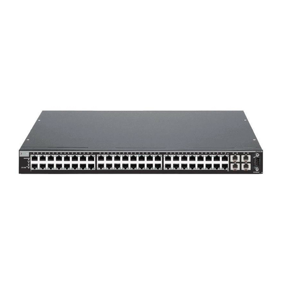
Overview Overview The B2G124‐24, B2G124‐48, and B2H124‐48 are stackable Fast Ethernet and Gigabit Ethernet switches, which can be adapted and scaled to help meet your network needs. These switches provide a management platform and uplink to a network backbone for a stacked group of up to eight B2 switches. The four built‐in Small Form Pluggable (SFP) interface slots provide you with the option of installing Mini‐GBICs for 1000BASE‐SX/LX fiber‐optic connections and 1000BASE‐T copper connections. The switches also support the use of a redundant DC power supply to help prevent downtime due to an internal power supply failure in the switch or AC power source. You can install the switch on a flat surface or into a standard 19‐inch rack with user‐ supplied mounting hardware, and configure the switch functions using the WebView™ application, CLI switching commands, and/or SNMP. B2G124-24 and B2G124-48 The B2G124‐24 (Figure 1‐1) and B2G124‐48 (Figure rear panel port connections, which include: • RJ45 ports (10/100/1000 Mbps, 1000BASE‐T copper ports), 24 on the B2G124‐24 and 48 on the B2G124‐48 • SFP slots that provide you with the option of installing Small Form Pluggable (SFP) Mini‐GBICs for 1000BASE‐SX/LX fiber‐optic connections and 1000BASE‐T copper connections. • Rear panel connectors for high‐speed connections in a stack configuration • Rear panel Redundant Power Supply connector for a connection to a SecureStack C2RPS‐SYS power supply system using the appropriate cable (C2RPS‐PSM). Caution: The B2G124-24, B2G124-48 and B2H124-48 are not PoE-compliant devices. -
Page 23: B2G124-24 Stackable Switch
Figure 1-1 B2G124-24 Stackable Switch À Á Æ Ç 1 DB9 RS232 Console port connector 2 Status LEDs 3 Twenty-four RJ45, 10/100/1000 Mbps ports 4 RJ45 port status LEDs 5 Four slots for SFP interface modules (Mini-GBICs) Figure 1-2 B2G124-48 Stackable Switch Á... -
Page 24: B2H124-48
2 Status LEDs 3 Forty-eight RJ45, 10/100 Mbps ports 4 RJ45 port status LED 5 Four slots for SFP interface modules (Mini-GBICs) 1-4 Introduction (Figure 1‐3) has the following front and rear panel port connections: B2H124-48 Stackable Switch Ã Â Æ Ç È É 6 Mini-GBIC port status LEDs... -
Page 25: High-Speed Stack Connections
High-Speed Stack Connections The switches have rear‐panel connectors for high‐speed connections in a stack configuration. The high‐speed stacking cables used for the connections are optional items and must be ordered separately. Stacking cables are available in three lengths: 1 foot, 1 meter and 5 meters. See “Connecting High‐Speed Stacking Cables” on page 3‐10 for details on these cables. Redundant Power Supply Capability The switch has power supply redundancy capability when connected to an optional external redundant power supply (RPS). If the internal power supply fails, the RPS assumes the entire load of the switch without interrupting network traffic. The internal power supply and RPS each have their own AC power connection, which enables the connection of each power supply to a different AC power circuit for additional AC power source redundancy. Connectivity The switch connects to Ethernet networks or workstations via the fixed front panel RJ45 connectors and four uplink ports that support optional Mini‐GBICs. At the time of this printing, the Mini‐GBICs that are available from Enterasys and supported by B2 switches are described in Table or exceed the IEEE 802.3z‐1998 standard. 1‐1 on page 1‐6. These Mini‐GBICs meet SecureStack B2 Installation Guide Connectivity... -
Page 26: Description Of Mini-Gbics
Connectivity Table 1-1 Description of Mini-GBICs Mini-GBIC MGBIC-LC01 MGBIC-LC03 MGBIC-LC09 MGBIC-MT01 MGBIC-08 MGBIC-02 1-6 Introduction Specification Provides one 1000BASE-SX compliant LC fiber-optic multimode port and a standard LC connector. For optical and operating range specifications, refer to “MGBIC-LC01/MGBIC-MT01 Specifications Provides one 1000BASE-SX compliant LC fiber-optic multimode port with a standard LC duplex connector. -
Page 27: Management
Management Management of the module can be either in‐band or out‐of‐band. In‐band remote management is possible using Telnet, Enterasys Networks’ NetSight application, or the WebView application. Out‐of‐band management is provided through the DB9 Console port connector on the front panel using a VT100 terminal or a VT100 terminal emulator. Switch Configuration Using WebView Enterasys Networks’ HTTP‐based Web management application (WebView) is an intuitive web tool for simple management tasks. Switch Configuration Using CLI Commands The CLI commands enable you to perform more complete switch configuration management tasks. For CLI command set information and how to configure the module, refer to the SecureStack B2 Configuration Guide. Standards Compatibility The 1000BASE‐T ports are compliant with the following standards and operations: • IEEE 802.3 • IEEE 802.3u • IEEE 802.3ab • Full‐Duplex operation The SFP ports are compliant with the following standards and operations: • IEEE 802.3z • IEEE 802.3x Flow Control support for Full‐Duplex mode •... -
Page 28: Getting Help
• Network load and frame size at the time of trouble (if known) • The device history (that is, have you returned the device before, is this a recurring problem, and so forth.) • Any previous Return Material Authorization (RMA) numbers 1-8 Introduction www.enterasys.com/services/support/ 1-800-872-8440 (toll-free in U.S. and Canada) or 1-978-684-1000 For the Enterasys Networks Support toll-free number in your country: www.enterasys.com/services/support/contact/ support@enterasys.com To expedite your message, type [SWITCHING] in the subject line. -
Page 29: Chapter 2: Network Requirements
Failure to do so will produce poor network performance. Note: The SecureStack B2 Configuration Guide and the Cabling Guide referred to in the following sections can be found on the Enterasys Networks World Wide Web site: http://www.enterasys.com/support/manuals For details about obtaining the manuals, refer to 10BASE-T Network When connecting a 10BASE‐TX segment to one of the RJ45 fixed ports (1 through 24 on ... -
Page 30: 100Base-Tx Network
802.3‐2002 100BASE‐TX Fast Ethernet network requirements for the switches to operate at 100 Mbps. Note: When using the fixed ports on the switch for 100 Mbps operation use Category 5 UTP cabling with an impedance between 85 and 111 ohms for 100 Mbps operation. The fixed switch ports are capable of operating at 10, 100, or 1000 Mbps. This is accomplished by the switch when Auto-Negotiation is enabled. -
Page 31: Hardware Installation
Riesgo Electrico: Solamente personal calificado debe realizar procedimientos de instalacion. Elektrischer Gefahrenhinweis: Installationen sollten nur durch ausgebildetes und qualifiziertes Personal vorgenommen werden. Read the Release Notes shipped with the switch to check for any exceptions to the supported features and operation documented in this guide. This chapter provides instructions to install the B2G124‐24, B2G124‐48, and B2H124‐48. Unless otherwise noted, the instructions apply to all switches. Follow the order of the ... -
Page 32: Considerations Prior To Installation
Rubber feet with adhesive backing for installation on a flat surface AC power cord (The type of power cord is country dependent.) This installation guide Customer Release Notes URL notice card Remove the tape seal on the non‐conductive bag to remove the switch. Perform a visual inspection of the switch for any signs of physical damage. Contact Enterasys Networks if there are any signs of damage. Refer to “Getting Help” on page 1‐8 for details. 3-2 Hardware Installation 3‐1. Quantity... -
Page 33: Installing Optional Mini-Gbics
Installing Optional Mini-GBICs This section describes how to install Mini‐GBICs in any of the SFP port slots (21 through 24 of B2G124‐24; 45 through 48 of B2G124‐48, or 49 through 52 for B2H124‐48). It is recommended that the options be installed first in a new installation. Warning: Fiber-optic Mini-GBICs use Class 1 lasers. Do not use optical instruments to view the laser output. The use of optical instruments to view laser output increases eye hazard. When viewing the output optical port, power must be removed from the network adapter. -
Page 34: Installation
Installing Optional Mini-GBICs Installation To install a Mini‐GBIC that has an MT‐RJ connector, refer to Figure with an LC connector, refer to Figure Hold the Mini‐GBIC with the top side positioned as shown, and the 7‐pin edge connector facing the port slot. Align the Mini‐GBIC with the port slot. Push the Mini‐GBIC into the port slot until the Mini‐GBIC “clicks” and locks into place. Figure 3-1 Ä 1 Mini-GBIC (MGBIC-MT01) 2 Mini-GBIC 3 7-pin edge connector (insertion side) 3-4 Hardware Installation 3‐2, and proceed as follows: Mini-GBIC with MT-RJ Connector Á Â À Å top side 3‐1, or for a Mini‐GBIC Ã... -
Page 35: Mini-Gbic With Lc Connector
Mini-GBIC. This can damage the Mini-GBIC. The Mini-GBIC and its host switch are sensitive to static discharges. Use an antistatic wrist strap and observe all static precautions during this procedure. Failure to do so could result in damaging the Mini-GBIC or host switch. -
Page 36: Installing The Switch On A Flat Surface
Installing the Switch on a Flat Surface Locate the release tab under the front end of the Mini‐GBIC. For the type of Mini‐GBIC shown in Figure the Mini‐GBIC from the port slot. For the type of Mini‐GBIC shown in Figure out on the release tab to release the Mini‐GBIC from the port slot. Grasp the sides of the Mini‐GBIC and pull it straight out of the port slot. If storing or shipping a Mini‐GBIC, which has a fiber‐optic connector, insert its protective dust cover to protect the ends of the fiber‐optic fibers from dust or contamination. Installing the Switch on a Flat Surface When installing the switch on a flat surface, the installation of the rubber feet is recommended to prevent the switch from sliding on a flat surface. Installing the rubber feet is optional if you are installing the switch in a rack. To install the rubber feet, proceed to “Installing the Rubber Feet” instructions below. For instructions to rack mount the switch, proceed to “Rack Mounting the Switch” on page 3‐9. Installing the Rubber Feet To install the rubber feet, refer to Figure Place the switch on its back on a sturdy flat surface to gain access to the bottom of the chassis. Remove the four rubber feet from their plastic bag in the shipping box. Locate the four marked locations on the bottom four corners of the chassis. 3-6 Hardware Installation 3‐1, push in on the release tab as far as it will go to release ... -
Page 37: Chassis Bottom, Rubber Feet Placement
After installing the rubber feet, return the switch to its upright position. Note: If a number of switches are being installed in a stack, repeat steps 1 through 4 to install the rubber feet on each switch before continuing with the installation. Proceed to “Guidelines for Flat Surface Installation” on page 3‐8. For a rackmount installation, proceed to “Rack Mounting the Switch” on page 3‐9. Installing the Switch on a Flat Surface À... -
Page 38: Guidelines For Flat Surface Installation
Caution: To ensure proper ventilation and prevent overheating, leave a minimum clearance space of 5.1 cm (2.0 in.) at the left, right, and rear of the switch. Do not connect the switch to the AC power source until instructed to do so later in the installation process. -
Page 39: Rack Mounting The Switch
Note: To ensure proper ventilation and prevent overheating, leave a minimum clearance space of 5.1 cm (2.0 in.) at the left, right, and rear of the switch. Warning: Before rack-mounting the switch, ensure that the rack can support it without compromising stability. -
Page 40: Connecting High-Speed Stacking Cables
“Connecting AC and RPS‐SYS Power” on page 3‐15. Connecting High-Speed Stacking Cables The stack of switches can be connected in a ring or daisy chain topology. In a ring topology all the switches are connected. The only difference in the cable connections in a daisy chain topology is that one cable is not installed. Up to seven or eight switches can be stacked together and connected by high‐speed stacking cables. You can add switches and reach up to a maximum of 384 Ethernet ports per stack. The high‐speed stacking cables allow the entire stack to operate with a single IP address. 3-10 Hardware Installation Attaching the Rackmount Brackets Fastening the Switch to the Rack 2 Mounting screws (supplied by user) 2 M3x6 mm flathead screws 3‐6. Then fasten the switch securely Á À À Á... - Page 41 The high‐speed stacking cables are optional items and must be ordered separately. The B2G124‐48 and B2H124‐48 support three types of SecureStack stacking cables: • C2CAB‐SHORT cable to connect two adjacent switches in the stack. If the stack is in a configuration where the adjacent switches are too far apart for the SHORT cables, the LONG cable can be used for the connections. • C2CAB‐LONG cable to connect from the top switch to the bottom switch in the stack. You need only one C2CAB‐LONG cable per stack. • C2CAB‐5M cable to connect from the top switch to the bottom switch in the stack when these two switches are physically located in seperate mounting racks and require a longer cable reach. Note: The B2G124-24 supports only the C2CAB-SHORT and C2CAB-LONG stacking cables. Figure 3‐7 shows an example of a four‐high stack connected in a ring topology. All STACK DOWN and STACK UP connectors are used in the installation. The high‐speed stacking cable connections are from the STACK DOWN connector of one switch to the STACK UP connector of the next switch up in the stack. A high‐speed stacking cable connection from the STACK DOWN connector of the switch at the top of the stack to the STACK UP connector at the bottom of the stack completes the ring connection. In a daisy chain topology, one cable connection is not made. Connecting High-Speed Stacking Cables SecureStack B2 Installation Guide...
-
Page 42: Configuring Switches In A Stack
High-speed stacking cable STACK DOWN connector STACK UP connector After connecting the cables to the stacking ports, proceed to “Configuring Switches in a Stack” on page 3‐12 for instructions. Configuring Switches in a Stack The information in the following sections is important to understand B2 switch operation and installations in a stack installation. About SecureStack B2 Switch Operation in a Stack The SecureStack B2 products are stackable switches that can be adapted and scaled to help meet your network needs. These switches provide a management platform and uplink to a network backbone for a stacked group of up to eight B2 switches. 3-12 Hardware Installation High-Speed Stacking Cable Connections à  Á... - Page 43 Once installed in a stack, the switches behave and perform as a single switch. As such, you can start with a single switch and add more switches as your network expands. You can also mix different products in the family in a single stack to provide a desired combination of port types and functions to match the requirements of individual applications. In all cases, a stack of switches performs as one large product, and is managed as a single network entity. When switches are installed and connected as described back in “Connecting High‐Speed Stacking Cables” on page 3‐10, the following occurs during initialization: • The switch that will manage the stack is automatically established and is referred to as the Manager switch. • All other switches are established as Member switches in the stack. • The hierarchy of the switches that will assume the function of backup manager is also determined in case the current manager malfunctions, is powered down, or is disconnected from the stack. • The Console port on the manager switch remains active for out‐of‐band (local) switch management, but the Console port on each member switch is deactivated. This enables you to set the IP address and system password using a single Console port. Now each switch can be configured locally using only the manager’s Console port, or in‐band using a remote device and the CLI set of commands described in this section. For procedures used for various types of connections to the Console port, refer to “Connecting to Console Port for Local Management” on page 3‐18. Once a stack is created (more than one switch is interconnected), the following occurs: Switch (unit) IDs are arbitrarily assigned on a first‐come, first‐served basis. Switch IDs are saved against each module. Then, every time a board is power‐cycled, it will initialize with the same switch ID. This is important for port‐specific information (for example: ge.4.12 is the 12th Gigabit Ethernet port on switch number 4). The management election process uses the following precedence to assign a management switch: Previously assigned/elected management switch b. Management assigned priority (values 1–15) Hardware preference level d.
-
Page 44: Recommended Procedures For New And Existing Stacks
The following procedures assume that all switches have a clean configuration from manufacturing. When adding a new switch to an already running stack, it is also assumed that the new switch is using the same firmware image version as other switches in the stack. -
Page 45: Adding A New Switch To An Existing Stack
• Use clear config to clear config parameters without clearing stack switch IDs. This command WILL NOT clear stack parameters and avoids the process of re-numbering the stack. • Use clear config all when it is necessary to clear all config parameters, including stack switch IDs and switch priority values. -
Page 46: Switch Rear View
Note: If the CPU LED illuminates solid red, there was a critical failure. For more information about the LED indications and troubleshooting, refer to additional help, contact Enterasys Networks. Refer to details If the switch is a standalone switch, it will take approximately 30 seconds for the switch to start up. If the switch is a stack Manager, it can take up to 3 minutes or more to start up, depending on the number of Member switches in the stack. 3-16 Hardware Installation Switch Rear View Á... -
Page 47: C2Rps-Sys Redundant Power System
C2RPS-SYS Redundant Power System If you are installing an optional redundant power system (C2RPS‐SYS), refer to the installation instructions supplied with the SecureStack RPS. The switch is connected to a C2RPS‐PSM using a C2RPS‐PSM Cable. Caution: To prevent damaging the switch, DO NOTconnect a Power over Ethernet-compliant Redundant Power System (C2RPS-POE) to the redundant power supply connector. The switch is only compatible with the SecureStack C2RPS-SYS redundant power supply system. -
Page 48: Connecting To Console Port For Local Management
Note: When switches are connected in a stack configuration and all high-speed stacking cables are connected before powering up the switches, one switch in the stack will be automatically designated as the Manager of the stack and its Console port will remain active. -
Page 49: Connecting To An Ibm Or Compatible Device
Figure 3-9 DB9 Male Console Port Pinout Assignments  Á À Connecting to an IBM or Compatible Device To connect an IBM PC or compatible device, running the VT terminal emulation, to an Enterasys switch Console port (Figure Connect the DB9 female connector at one end of the cable (not supplied) to the Console port on the Enterasys switch. (If there is a switch designated as the Manager, connect to its Console port.) Plug the DB9 female connector at the other end of cable into the communications port on the PC. Turn on the PC and configure your VT emulation package with the following parameters: Parameter Mode Transmit Bits Parity Stop Bit When these parameters are set, the Startup screen will display. Proceed to “Connecting to the Network” on page 3‐22. Connecting to Console Port for Local Management... -
Page 50: Connecting To A Vt Series Terminal
Connecting to Console Port for Local Management Figure 3-10 1 DB9 female connector 2 Serial interface cable 3 DB9 male Console port connector Connecting to a VT Series Terminal To connect a VT Series terminal to an Enterasys switch Console port (Figure UTP serial interface cable terminated with a DB9 female connector and a DB25 female connector and proceed as follows: Connect the DB9 female connector at one end of cable to the Console port DB9 male connector on the Enterasys switch. (If there is a switch designated as the Manager, connect to its Console port.) Plug the DB25 female connector at the other end of the cable into the port labeled COMM on the VT terminal. Turn on the terminal and access the Setup Directory. Set the following parameters on your terminal: Parameter... -
Page 51: Connecting To A Modem
Figure 3-11 Connecting a VT Series Terminal 1 DB9 female connector 2 Serial interface cable 3 DB9 male Console port connector Connecting to a Modem To connect a modem to an Enterasys UTP cable terminated with a DB9 female connector and a DB25 male connector, and proceed as follows: Connect the DB9 female connector at one end of the cable to the Console port DB9 connector on the Enterasys switch. (If there is a switch designated as the Manager, connect to its Console port.) Plug the DB25 male connector at the other end of the cable into the modem communications port. Turn on the modem and make sure the remote modem is ON. With your PC connected to the remote modem, configure your VT emulation package with the following parameters: Parameter Mode Transmit Bits Parity Stop Bit When these parameters are set, the Startup screen will display. If the switches are in a ... -
Page 52: Connecting To The Network
Connecting to the Network Figure 3-12 1 DB9 female cable connector 2 Serial interface cable 3 DB9 male Console port Connecting to the Network The following procedures cover the cable connections from the network or other devices to the switch RJ45 ports or any installed optional Mini‐GBIC. • Connecting UTP Cables on page 3‐22 • Connecting Fiber‐Optic Cables to MT‐RJ Ports on page 3‐26 • Connecting Fiber‐Optic Cables to LC Ports on page 3‐28 Connecting UTP Cables The fixed RJ45 front panel ports are 10/100/1000 Mbps ports and have internal crossovers. When connecting a workstation to these ports, use a straight‐through cable. When ... -
Page 53: Connecting A Utp Cable Segment To Rj45 Port
Verify that the device at the other end of the twisted pair segment is on and properly connected to the segment. Verify that the RJ45 connectors on the twisted pair segment have the proper pinouts and check the cable for continuity. Typically, a crossover cable is used between hub devices. A straight‐through cable is used to connect between switches or hub devices and an end user (computer). Refer to Figure Figure 3‐15 for four‐wire RJ45 connections. Refer to Figure 3‐16 and Figure for eight‐wire RJ45 connections. d. Ensure that the twisted pair connection meets the dB loss and cable specifications outlined in the Cabling Guide. Refer to “Related Documents” on page xvi for information on obtaining this document. If a link is not established, contact Enterasys Networks. Refer to “Getting Help” on page 1‐8 for details. Repeat all steps above until all connections have been made. Connecting to the Network  3 Port 8 Link/Activity LED SecureStack B2 Installation Guide 3‐14 and 3‐17 3-23... -
Page 54: Four-Wire Crossover Cable Rj45 Pinouts For 10/100Base-Tx
Connecting to the Network Figure 3-14 1 RJ45 switch port 2 Other device port Figure 3-15 1 RJ45 switch port 2 Other device port 3-24 Hardware Installation Four-Wire Crossover Cable RJ45 Pinouts for 10/100BASE-TX À Ã 3 RJ45-to-RJ45 crossover cable 4 RX+/RX- and TX+/TX-connections These connections must share a common color pair. -
Page 55: Eight-Wire Straight-Through Cable Rj45 Pinouts For 10/100/1000Base-Tx
Figure 3-16 Eight-Wire Crossover Cable RJ45 Pinouts for 10/100/1000BASE-TX À 1 RJ45 device port 2 Other device port Figure 3-17 Eight-Wire Straight-Through Cable RJ45 Pinouts for 10/100/ 1000BASE-TX À 1 RJ45 device port 2 Other device port Á Â 3 RJ45-to-RJ45 crossover cable Á... -
Page 56: Connecting Fiber-Optic Cables To Mt-Rj Ports
This section contains the procedures for connecting a 1000BASE‐SX multimode fiber‐optic segment from the network or other devices to an MT‐RJ port connector in a Mini‐GBIC (MGBIC‐MT01). Each fiber‐optic link consists of two fiber‐optic strands within the cable: • Transmit (TX) • Receive (RX) The transmit strand from a switch port connects to the receive port of a fiber‐optic Gigabit Ethernet device at the other end of the segment. The receive strand of the applicable MT‐RJ port connects to the transmit port of the fiber‐optic Gigabit Ethernet switch. Enterasys Networks recommends labeling fiber‐optic cables to indicate receive and transmit ends. Many cables are pre‐labeled, providing matching labels or tapes at both ends of each strand of cable. To connect an MT‐RJ cable to a fixed MT‐RJ connector of a Mini‐GBIC, refer to Figure and proceed as follows: Remove the protective covers (not shown) from the front panel MT‐RJ fiber‐optic port (port 22 in this example) and from the connectors on each end of the cable. Note: Leave the protective covers in place when the connectors are not in use to prevent contamination. 3-26 Hardware Installation 3‐18 ... -
Page 57: Cable Connection To Mt-Rj Multimode Fiber-Optic Connectors
Caution: Do not touch the ends of the fiber-optic strands, and do not let the ends come in contact with dust, dirt, or other contaminants. Contamination of cable ends causes problems in data transmissions. If the ends of the fiber-optic strands become contaminated, use a canned duster to blow the surfaces clean. -
Page 58: Connecting Fiber-Optic Cables To Lc Ports
If a link has not been established, refer to Chapter a problem persists, refer to “Getting Help” on page 1‐8 for details on contacting Enterasys Networks for support. Repeat steps 1 through 4, above, until all connections have been made. Connecting Fiber-Optic Cables to LC Ports Warning: Fiber-optic Mini-GBICs use Class 1 lasers. Do not use optical instruments to view the laser output. The use of optical instruments to view laser output increases eye hazard. - Page 59 To connect an LC cable connector to a fixed LC connector of a Mini‐GBIC, refer to Figure 3‐19 and proceed as follows: Caution: Do not touch the ends of the fiber-optic strands, and do not let the ends come in contact with dust, dirt, or other contaminants. Contamination of cable ends causes problems in data transmissions. If the ends of the fiber-optic strands become contaminated, use a canned duster to blow the surfaces clean.
-
Page 60: Cable Connection To Lc Fiber-Optic Connectors
Verify that a link exists by checking that the port Link/Activity LED is on (blinking green or solid green). If the Link/Activity LED is off, perform the following steps until it is on: Verify that the device at the other end of the segment is ON and connected to the segment. b. If there are separate fiber‐optic connections on the other device, check the crossover of the cables. Swap the cable connections if necessary. Check that the fiber‐optic connection meets the dB loss and cable specifications outlined in the Cabling Guide for multimode mode cabling. To obtain this document, refer to “Related Documents” on page xvi. If a link has not been established, refer to Chapter details. If a problem persists, refer to refer to “Getting Help” on page 1‐8 for details on contacting Enterasys Networks for support. Repeat steps 1 through 4, above, until all connections have been made. 3-30 Hardware Installation Cable Connection to LC Fiber-Optic Connectors à  À Á 3 Release tab 4 Link/Activity LED 4 for LED troubleshooting ... -
Page 61: Completing The Installation
Completing the Installation After installing the switch and making the connections to the network, access the switch management, as described below. Initial Logon to Switch Management To initially access switch management from your local PC, terminal, or modem connection, proceed as follows at the displayed startup screen: Enter rw (Read‐Write) for Username. At the Password prompt, press Enter (RETURN). For details on how to configure the switch using the command line interface, refer to the SecureStack B2 Configuration Guide. The CLI commands enable you to set a new password and perform more involved management configurations on the switch. One of many capabilities is to reconfigure the stack, reassigning the Manager function to another switch and configuring the order of Member switches that will take over the stack management functions in case the operating Manager is powered down, malfunctions, or is removed from the stack. After the initial configuration, you can also use WebView (Enterasys Networks’ embedded web server) for configuration and management tasks. All the guides associated with the switch are available online at: http://www.enterasys.com/support/manuals Once you are confident that the installation is successful, route and secure your cables. If you require assistance, contact Enterasys Networks using one of the methods described in “Getting Help” on page 1‐8. Completing the Installation SecureStack B2 Installation Guide 3-31... - Page 62 Completing the Installation 3-32 Hardware Installation...
-
Page 63: Chapter 4: Troubleshooting
This chapter provides information concerning the following: For information about... Using LANVIEW Troubleshooting Checklist Using the Reset Switch This device contains a battery that is not considered a user replaceable part. If the battery needs to be replaced, contact customer service for repair. Caution: There is a risk of explosion if the battery is replaced with an incorrect type. A used battery may be safely disposed in a municipal waste stream. -
Page 64: Using Lanview
Using LANVIEW Using LANVIEW These switches support the Enterasys Networks built‐in LANVIEW LED visual diagnostic and status monitoring system. The LANVIEW LEDs on both the B2G124‐24 and B2G124‐48 are located in similar locations as shown on B2G124‐24 in Figure LANVIEW LEDs on the B2H124‐48 are shown in Figure quickly observe network status for diagnosing switch and network problems. Figure 4-1 1 CPU LED 2 STACK DOWN LED 3 STACK UP LED 4 RPS LED for redundant power-source status 5 Manager LED 6 Link/Activity LED for • B2G124-24/B2G124-48: 10/100/1000 Mbps, RJ45 port 1 1. -
Page 65: Lanview Leds Of B2H124-48
Figure 4-2 LANVIEW LEDs of B2H124-48 Å Ä Ã Â Á À 1 CPU LED 2 STACK DOWN LED 3 STACK UP LED 4 RPS LED for redundant power source status 5 Manager LED 1. Unlike the B2G124-24 or B2G124-48, all 52 ports may be active at the same time. Table 4‐1 describes the LED indications and provides recommended actions as ... - Page 66 2. Replace the power cord with a known good one or check the continuity of the power cord. 3. If the switch still does not power up, the system may have a fatal error. Contact Enterasys Networks for technical support.
- Page 67 Solid. Valid connection to switch stackdown connector. Blinking. Information is being transferred via the high-speed stacking cable. Manager Switch is operating as a Member in the stack. Green Solid. Switch is operating as the Manager of the stack. RPS not in use.
-
Page 68: Troubleshooting Checklist
None. None. None. 4‐2 for a checklist of problems, Recommended Action Ensure that the switch was installed properly according to the installation instructions in Chapter Ensure that the power cords are connected properly to an active power source that meets the AC input specifications for this switch. - Page 69 Configuration Guide for instructions to enable/disable ports. Verify that all network connections between the network management station and the device are valid and operating. If the problem continues, contact Enterasys Networks for technical support. Verify that Spanning Tree is enabled. Refer to the SecureStack B2 Configuration Guide for the instructions to set the type of STA.
-
Page 70: Using The Reset Switch
Using the Reset Switch Using the Reset Switch If you forget the switch login password, use the Reset switch as described in the following procedure. Figure 4-3 1 Reset switch To reset the switch password, refer to Figure Note: Notify the system manager before changing the password. Press‐and‐hold the Reset switch while the switch is operational. This change of the login password to the default password will be indicated via CLI only. Logon to switch management. You can now logon to the switch via the Console port and assign a new password using the command line interface (CLI). To access switch management from your local PC, terminal, or modem connection, refer to the SecureStack B2 Configuration Guide for instructions on how to log in and enter a new password. The guide is available online under the C category at: http://www.enterasys.com/support/manuals If you require assistance, contact Enterasys Networks using one of the methods described in “Getting Help” on page 1‐8. 4-8 Troubleshooting Reset Switch À... -
Page 71: Appendix A: Specifications
This appendix provides information about the following: For information about... Switch Specifications Mini-GBIC Input/Output Specifications Gigabit Ethernet Specifications MGBIC-02 Specifications (1000BASE-T) Regulatory Compliance Enterasys Networks reserves the right to change the specifications at any time without notice. Switch Specifications Table A‐1 provides the I/O ports, processors and memory, physical, and environmental specifications for the B2G124‐24, B2G124‐48, and B2H124‐48. Table A-1 Switch Specifications Item B2G124-24 RJ45 ports 1 through 24 SFP ports 21 through 24... -
Page 72: Switch Specifications
Switch Specifications Table A-1 Switch Specifications (continued) Item B2G124-48 RJ45 ports 1 through 48 SFP ports 45 through 48 B2H124-48 RJ45 ports 1 through 48 SFP ports 49 through 52 Processors/Memory Processor Dynamic Random Access Memory (DRAM) - Page 73 Table A-1 Switch Specifications (continued) Item Specification Predicted hours for Mean For the MTBF hours for these products, refer to the MTBF web Time Between Failures site at URL (MTBF) Heat Dissipation (maximum) B2G124-24 @ 86.40 W, 294.80 Btu/hr B2G124-48 @ 129.50 W, 441.87 Btu/hr...
-
Page 74: Mini-Gbic Input/Output Specifications
Mini-GBIC Input/Output Specifications Mini-GBIC Input/Output Specifications The Mini‐Gigabit Ethernet Card (Mini‐GBIC) port interface slots can support 1‐Gbps fiber‐optic connections as described in Table swappable. Table A-2 Mini-GBIC Input/Output Port Specifications Item MGBIC-LC01 MGBIC-LC03 MGBIC-LC09 MGBIC-MT01 MGBIC-08 MGBIC-02 Gigabit Ethernet Specifications The following specifications for the Mini‐GBICs shown in Table A‐3 through Table meet or exceed the IEEE 802.3z‐1998 standard. MGBIC-LC01/MGBIC-MT01 Specifications (1000BASE-SX) Table A-3 MGBIC-LC01/MGBIC-MT01 Optical Specifications Item Transmit Power (minimum) Receive Sensitivity Link Power Budget A-4 Specifications... -
Page 75: Mgbic-Lc03 Specifications (1000Base-Sx
Table A-4 MGBIC-LC01/MGBIC-MT01 Operating Range Item 62.5 µm MMF 62.5 µm MMF 50 µm MMF 50 µm MMF MGBIC-LC03 Specifications (1000BASE-SX) Table A-5 MGBIC-LC03 Optical Specifications Item Transmit Power (minimum) Transmit Power (maximum) Receive Sensitivity Link Power Budget (Multimode Only) 1. -
Page 76: Mgbic-Lc09 Specifications (1000Base-Lx
Gigabit Ethernet Specifications MGBIC-LC09 Specifications (1000BASE-LX) Table A-7 MGBIC-LC09 Optical Specifications Item Transmit Power (minimum) Receive Sensitivity Link Power Budget Table A-8 MGBIC-LC09 Operating Range Item 62.5 µm MMF 50 µm MMF 50 µm MMF 10 µm SMF MGBIC-08 Specifications (1000BASE-ELX) Table A-9 MGBIC-08 Optical Specifications Item Transmit Power (minimum) -
Page 77: Mgbic-02 Specifications (1000Base-T
MGBIC-02 Specifications (1000BASE-T) Table A-11 MGBIC-02 Specifications Item Supported Cable: Type Maximum Length Connector Data Rate TX Output impedance RX Input impedance Console Port Pinout Assignments The Console port is a DB9 serial communications port for local access to Local Management. Refer to Figure Figure A-1 Pin 2, Received Data (input) Pin 3, Transmitted Data (output) Specification Copper, Category 5 UTP Up to 100 meters... -
Page 78: Regulatory Compliance
Regulatory Compliance Regulatory Compliance The B2G124‐24, B2G124‐48, and B2H124‐48 meet the safety and electromagnetic compatibility (EMC) requirements listed in Table Table A-12 Compliance Standards Regulatory Compliance Safety Electromagnetic Compatibility (EMC) A-8 Specifications A‐12: Standards UL 60950, CSA C22.2 No. 60950, 73/23/EEC, EN 60950, and IEC 60950. The Mini-GBICs that support laser connections also meet the EN 60825 and 21 CFR 1040.10 standards. - Page 79 Installation connecting to the network 3-22 high-speed stacking cables 3-10 in a rack new stack 3-14 new switch in existing stack 3-15 optional Mini-GBIC Installation site what is needed at the LANVIEW Diagnostic LEDs introduction to LANVIEW LEDs Link LEDs...
- Page 80 3-17 Index-2 Stack Member automatic selection of Stack operation Member switch selection Stack System 3-24 installation of a new switch in existing stack installation of new 3-25 Standalone Switches specifications for Standards compatibility Switch overview of Switch carton...
Need help?
Do you have a question about the Enterasys SecureStack B2 B2G124-24 and is the answer not in the manual?
Questions and answers