
Related Manuals for Automatic Technology Axess Pro 1505


Summary of Contents for Automatic Technology Axess Pro 1505
- Page 1 Axess Pro 1505 ® Industrial Overhead Door Opener Doc # 160052_01 Part # 13436 Released 25/06/15...
-
Page 2: Table Of Contents
Axess Pro 1505 ® Industrial Overhead Door Opener Contents 1. Important Safety Instructions 2. Controller Input And Outputs 3. Operating Controls 4. Kit Contents 5. Pre-Installation 5.1 Initial Check 5.2 Drive Unit Pre-assembly 6. Installation 7. Programming The Opener 8. Setting Limits via Console 9. - Page 3 Door opener. Automatic Technology (Australia) Pty Ltd hereby further expressly excludes all or any liability for any injury, damage, cost, expense or claim whatsoever suffered by any person as a result whether directly or indirectly from failure to install the Automatic Technology (Australia) industrial roller Door opener in accordance with these installation instructions.
-
Page 4: Important Safety Instructions
Disconnect the power cord from mains power before making any repairs or removing covers. Only experienced service personnel should remove covers from the opener. • If the power supply cord is damaged, it must be replaced by an Automatic Technology service agent or suitably qualified person. •... -
Page 5: Controller Input And Outputs
2. Controller Input And Outputs Fig 2.1 Motor identification harness connector Serial interface connector Position sensor connector 10 Amps slow blow mains fuse Installation Instructions Axess Pro 1505 ®... -
Page 6: Operating Controls
3. Operating Controls Fig 3.1 - Logic Console Programmer PG-3 Input Terminal Block ( From Left To Right ) Console Previous Button V2 Console: AUX OUT Receiver’s Auxiliary Output Liquid Crystal Display Accessory Supply Third Safety Beam Input Console Next Button Second Safety Beam Input Console Open Button First Safety Beam Input... -
Page 7: Kit Contents
4. Kit Contents Fig 4.1 ITEM DESCRIPTION ORDER CODE AXESS 1505 V1 POWER DRIVE PACK 18105 LOGIC CONSOLE V2 61565 PTX-5V2 TC-128 TRANSMITTERS 61167 SAFETY BEAMS WITH WIRES AND BRACKETS 61904 BENT ARM 62800 STRAIGHT ARM 62790 ACCESSORY PACK NILOCK NUT M8 10860 WALL BRACKET 62525... -
Page 8: Pre-Installation
5. Pre-Installation IMPORTANT SAFETY INSTRUCTIONS FOR INSTALLATION Warning: Incorrect installation can lead to severe injury. Follow ALL installation instructions. The Axess ® Pro 1505 is designed to operate most commercial and heavy residential overhead doors. 5.1 Initial Check Before commencing installation, check the following: a. -
Page 9: Installation
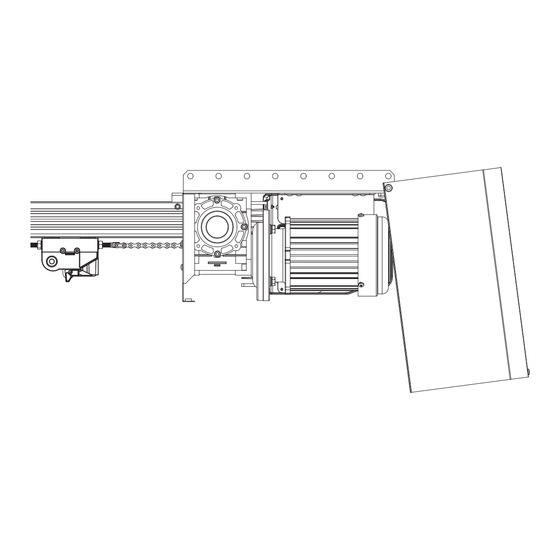
6. Installation THIS PRODUCT REQUIRES A TWO PERSON LIFT TO MOUNT ON MOST DOORS - use proper lifting techniques and equipment to suit the site. 6.1 Mounting The Drive Unit a. Determine the centre of the door and mark this point on 6.1). -
Page 10: Programming The Opener
6. Installation j. The door bracket comes in two parts. The door bracket locator is placed over the door bracket and uses 4 mounting holes for extra strength. Mount the door bracket to the centre line of the door (Fig. 6.5), using M6 or equivalent screws (not supplied). -
Page 11: Setting Limits Via Console
8. Setting Limits via Console 8.1 Setting Travel Limits with Logic Console To Desired a. Turn on the power to the opener. The controller will go through a start up sequence. CLOSE Limit, 8.1) will be displayed. b. After a short delay the MAIN SCREEN (Fig. -
Page 12: Setting Limits Via Transmitter
9. Setting Limits via Transmitter In order to use a transmitter to set the limits, it must first have at least one of its buttons coded to the logic console. The function assigned MENU 1 to the transmitter’s buttons is of no concern here as the buttons are Code Transmitter temporally assigned to OPEN, CLOSE and SET (Fig. -
Page 13: Coding Transmitter
10. Coding Transmitter The Axess Pro 1505 can store 511 transmitters in its memory. ® IMPORTANT NOTE: Each transmitter can be allocated an alpha-numeric ID label up to Only TrioCode 128 Technology Transmitters are eleven characters in length and each button can be assigned to compatible with the Axess Pro 1505 product. -
Page 14: Remotely Coding Transmitters
11. Remotely Coding Transmitters If a transmitter is already coded into the opener, additional transmitters can be coded without being in direct contact with the opener’s wall console unit. NOTE: Only the function of the existing transmitter button can be assigned to new transmitter. -
Page 15: Auto-Close Mode For Console
Door. Details about the four Auto-Close configured to activate Safety Beam Auto-Close mode. modes follow. Automatic Technology strongly recommend using a Safety Beam for added safety. Menu 3.6 (Safety Beam) Pedestrian Auto-Close Menu 3.1 Standard Auto Close... -
Page 16: Time Clock
14. Time Clock MENU 7.1 The opener provides a programmable time clock which can be used to Set Time/Date control the Axess ® Pro 1505 on a timed basis at various times of the week. This section details the time clock operation and configuration. Fig 14.1 14.1 Time Clock Operation The time clock consists of a 7 day clock and storage for 32 programs. -
Page 17: Day Light Saving Time Adjustment
Check your local Refer to the Automatic Technology website for information on where regulations for appropriate disposal of to recycle batteries in Australia. the batteries. -
Page 18: Accessories Installation
17. Accessories Installation 17.1 Fitting Courtesy Lights A light relay module (optional) can be connected to the aux out on the console to control the courtesy light. WARNING: A qualified electrician must perform the installation where 240V AC power is used. Menu 4. -
Page 19: Troubleshooting
19. Troubleshooting Symptom Possible cause Remedy Blank display screen. Mains power not switched on. Switch on mains power. Communication cable not connected. Connect the communication cable. Drive unit cover is lose or missing. Install / secure drive unit cover. Logic console displays Hand chain is not freely hanging. -
Page 20: Maintenance
20.5 Service Indicator • Lubricate the drive chain. As a reminder the Axess Pro 1505 has a built in maintenance • Guide Tracks: Clean the internal sections of the guide counter. This counter has a factory default of 60,000 cycles, tracks with a cloth dampened with mineral turps or and it is adjustable from 0 to 60,000 cycles. -
Page 21: Appendix
21. Appendix OPERATIONAL BUTTONS: 1. Press PREV/NEXT buttons move to Left/Right. 2. Press OPEN/CLOSE buttons to change setting. A - Console Menu Structure 3. Press SET button to save changes. 4. Press STOP to return to MENU without saving changes. NOTE: The System will automatically return to the main screen after 30 secs if a menu screen is displayed and no buttons are pressed. - Page 22 Appendix A - Console Menu Structure Parameter Default Step Unit Menu Section Menu 6 - Operating Modes Safety Close Mode 13.1 Safety Open Mode Appendix C Safety Beam Input Response Mode Sets the S.B response OPN & CLS stop CLS to 6.3-5 Appendix C mode.
- Page 23 Appendix A - Console Menu Structure Parameter Default Step Unit Menu Section Menu 8 - Diagnostics TEST INPUTS - Controls input display status Inactive Appendix D TEST TRANSMITTERS (TX’ERS) Appendix D DISPLAY HISTORY Appendix D MEMORY USAGE Appendix D SERVICE COUNTER 60,000 Appendix D EVENT COUNTER...
-
Page 24: B - Viewing & Editing Logic Console Parameters
Appendix B - Viewing & Editing Logic Console Parameters This section illustrates how to locate, view and adjust View Mode (No cursor) parameters in the logic console unit. Parameter number Parameter in sub menu name Locating parameters Refer to the CONSOLE MENU STRUCTURE or the 2: 100% O/L Time Parameter preceding section for CONTROL BOARD ADJUSTMENTS. -
Page 25: C - Control Board Adjustments
Appendix C - Control Board Adjustments The standard operation of the opener can be altered by editing various parameters. This section describes the parameters and the effect they have. Use the VIEWING AND EDITING PARAMETER PROCEDURE (Appendix B) to make changes. Menu 2 Current Trips Menu 6.6 Safety Beam Obstruction Reverse Time Mode Motor overload detection is provided to protect the Door... - Page 26 This parameter enables activity report outputs. Contact Automatic Technology for more details. 6.15 Activity Report ID This parameter sets the ID of the controller that is sent with the activity report. Contact Automatic Technology for more details. 6.16 Vacation Mode Vacation Mode blocks all but one designated remote control transmitter from activating the Axess Pro 1505.
-
Page 27: D - Diagnostic Tools
Appendix D - Diagnostic Tools The controller provides several diagnostic tools from within the Diagnostics Menu (Menu 8). This section details the function of each tool and its use. MENU 8 Navigating To Diagnostics Menu Diagnostics D.1). a. Press PREV to navigate to Menu 8 (Fig. -
Page 28: E - Memory Tools
Appendix D - Diagnostic Tools Menu 8.5 Service Counter The opener provides a periodic service counter which can be set to expire after a number of drive cycles. When expired, the opener will beep three Service Counter times at the beginning of each drive cycle and a message will be displayed (Cycles) 60000 (Fig. -
Page 29: F - Transmitter Editing
Appendix F - Transmitter Editing Display Transmitter Record Using one of the methods below, you can display the required transmitters details. MENU 1 Code Transmitter Navigating To “Edit Transmitter” Menu (Fig. F.1) a. Press NEXT to navigate to Menu 1 b. - Page 30 Appendix F - Transmitter Editing Editing The Store Location This feature is only available when coding the first button of a new 14 I [No Name] transmitter. OSC PED LGT VAC a. Press NEXT or PREV to move the cursor over Store No. (Fig.
-
Page 31: G - Transmitter Management
Appendix G - Transmitter Management Transmitter Listing Facility The Axess Pro 1505 provides a transmitter listing facility which enables the ® MENU 1 user to find a transmitter location within the memory. Once located a stored Code Transmitter transmitter can be replaced, deleted, edited, copied or, if the location is empty, a new transmitter can be coded. -
Page 32: Warranty And Exclusion Of Liability
Warranty and Exclusion of Liability c. incorrect installation of the Product; 1. This Warranty is given by Automatic Technology (Australia) Pty Ltd (ABN d. blown fuses, electrical surges, power surges or power spikes; 11 007 125 368) (ATA). 6-8 Fiveways Boulevard, Keysborough 3173, 1300 e.
Need help?
Do you have a question about the Axess Pro 1505 and is the answer not in the manual?
Questions and answers