Table of Contents
Advertisement
Advertisement
Table of Contents

Related Manuals for Automatic Technology DOMINATOR EasyRoller 14


Summary of Contents for Automatic Technology DOMINATOR EasyRoller 14
- Page 1 DOMINATOR ® EasyRoller Rolling Door Opener Instruction Manual Conforms to UL 325 4008033 (Instruction d’Installation) Certified to CSA C22.2 No.247 GDO-6V5CAM GDO-6V5AM FOR USE WITH EITHER RESIDENTIAL OR LIGHT-DUTY COMMERCIAL DOORS Doc # 160490_01 Part # 100647 Released 20/12/22...
-
Page 2: Table Of Contents
CONTENTS Rolling Garage Door Operator 1. System Specifications 6.8 Testing & Setting Safety Obstruction Force 2. Safety Information 6.8.1 Testing the Close Cycle 6.8.2 Testing the Open Cycle 3. Kit Contents 6.8.3 To Increase Force Pressure 4. Setup Requirements 6.8.4 To Decrease Force Pressure 4.1 Tools Required 6.8.5 To Recall Factory Set Force 4.2 The Opener:... -
Page 3: System Specifications
© Copyright 2018 1. System Specifications ® ® Technical Specifications Dominator EasyRoller Dominator EasyRoller GDO-6V5AM GDO-6V5CAM Power supply 120Va.c. 60Hz 120Va.c. 60Hz Type of door: Rolling Sheet Door Rolling Sheet Door Maximum Door Weight: 242lb 242lb Maximum Door Area: 178ft 178ft Door must be well balanced and able to be operated by hand,... -
Page 4: Safety Information
2. Safety Information Please read these important safety rules WARNING! It is vital for the safety of persons to follow all instructions. Failure to comply with the installation instructions and the safety warnings may result in serious personal injury and/or property and These safety alert... - Page 5 © Copyright 2018 2. Sécurité Lisez attentivement ces règles de AVERTISSEMENT ! pour la sécurité des sécurité. usagers, il est essentiel de suivre toutes les instructions. Le non- respect des instructions d’installation et des avertissements de sécurité peut causer de pictogrammes indiquent consigne...
-
Page 6: Kit Contents
3. Kit Contents (ii) Dominator EasyRoller 1 x Wired Safety Beam kit with brackets and screws a. 1 x GDO-6V5AM Drive unit with Adaptor kit OR 1 x Weight Bar b. 1 x GDO-6V5CAM Drive unit with Prong kit 2 x Nilock Nut (i) 2 x Rounded Prongs kit OR ”... -
Page 7: The Opener
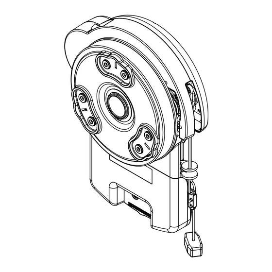
© Copyright 2018 4. Setup Requirements 4.2 The Opener: MUST BE installed in a dry position, protected from weather. (Moisture or corrosion not covered by Warranty) Is factory set for RIGHT HAND SIDE installation (from inside garage), but capable of LEFT HAND SIDE installation. Fig 4.2.1 REQUIRES properly earthed 3 pin single phase power within an arms length of door and at a suitable height Requires a MINIMUM SIDEROOM of 1 ”... -
Page 8: Operator Safety & Security
5. Operator Safety & Security 5.1 Your Door CAN NOT be used by the opener when: MANUAL RELEASE There is a locking device installed. There is a power failure. 5.2 Your Door CAN be used when: There is an emergency, by disengaging the opener. WARNING! When operating the manual 2 . -
Page 9: Installation Instructions
© Copyright 2018 6. Installation Instructions IMPORTANT INSTALLATION INSTRUCTIONS. WARNING - To reduce the risk of severe injury or death: (1) READ AND FOLLOW ALL INSTALLATION INSTRUCTIONS. (2) Install only on a properly operating and balanced sheet door. An improperly balanced door has the potential to inflict severe injury. -
Page 10: Door Preparation
6.1. Door Preparation 6.1.1 Prepare the Door: Clean the guides if there is any oil or wax present using a suitable white spirit. The only lubricant suitable for use on door guides is silicon spray. DO NOT use WD-40, RP-7, petroleum grease, or similar. Remove the locking bars or disable the lock. -
Page 11: Pinning The Door
© Copyright 2018 6.3. Pinning the Door 6.3.1 Pinning the Door to the drum: Screw into the NOTE: Pinning of the door is mandatory and is primarily required in order for the inherent low part of grove entrapment protection to function properly. Pinning the door’s curtain to its drum maintains security when the opener is closed. -
Page 12: Mounting The Opener
6.5. Mounting the Opener 6.5.1 Raising the Door: When in position, remove the U-bolt (or bolts) and saddle from the door bracket. Lift the door up and away from the wall until clear of the door bracket, before lowering the door to rest on the door stand or prop. -
Page 13: Safety Beam Installation
© Copyright 2018 6.6 Safety Beam Installation CAUTION: The Safety Beam must be installed and connected before the travel limits are set. ATTENTION: Le faisceau de sécurité doit être installé et connecté avant de définir les fins de course. 6.6.1 Safety Infra-Red Beam Kit (P/N 62047) A Safety Beam extends across the door opening. -
Page 14: Setting The Travel Limits
6.7. Setting the Travel Limits 6.7.1 Initial Preparation: S E T T I N G L I M I T S When setting the Close limit, ensure the position CAUTION: Limit setup is not available when running is when the door makes rst contact with the on battery backup ground. -
Page 15: Clearing The Door Limit Positions
© Copyright 2018 6.7. Setting the Travel Limits 6.7.3 Clearing the Door Limit Positions 6.7.4 Controller Memory Reset To clear the controller: C O N T R O L L E R M E M O R Y R E S E T NOTE: If unhappy with the travel limit settting, restart this If limits are already set, clear limits rst by following procedure by clearing the door limit positions as per below... -
Page 16: Testing & Setting Safety Obstruction Force
6.8 Testing & Setting Safety Obstruction Force 6.8.1 Testing the Close Cycle CAUTION: Take care when testing the safety T E S T I N G T H E C L O S E C Y C L E obstruction force. Excessive force may cause serious S T E P O N E personal injury and/or property damage can result S T E P T W O... -
Page 17: To Increase Force Pressure
© Copyright 2018 6.8 Testing & Setting Safety Obstruction Force Adjusting Safety Obstruction Force WARNING! Risk of entrapment. After adjusting either the The safety obstruction force is calculated automatically and set in force or limits of travel, retest the door opener. The door memory on the operator. -
Page 18: Accessories
6.9 Accessories 6.9.1 Terminal Block A variety of wired accessory items can be connected to the terminal block such as Safety Beam, Electric Key Switch and more (Fig. 6.9.1). Terminal connections from top down are as follows: (+35V/+24V); (Safety Beam input, mandatory); (0V for Safety Beam);... -
Page 19: Coding Transmitters
© Copyright 2018 6.10 Coding Transmitters TRANSMITTERS COMPLIANCE STATEMENT TRANSMITTERS COMPLY WITH ALL UNITED STATES AND CANADIAN LEGAL REQUIREMENTS AS OF THE DATE OF MANUFACTURE. TO COMPLY WITH FCC PART 15 AND OR RSS 210 INNOVATION, SCIENCE AND ECONOMIC DEVELOPMENT CANADA RULES, ADJUSTMENT OR MODIFICATIONS OF THIS RECEIVER AND / OR TRANSMITTER ARE PROHIBITED, EXCEPT FOR CHANGING THE CODE SETTING OR REPLACING THE BATTERY. -
Page 20: Setting Transmitters Codes
S T E P O N E S T E P T W O Press to test 6.10 Coding Transmitters HOLD for 3 sec HOLD RELEASE Opener beeps HOLD for 3 sec Release both buttons 6.10.1 Setting Transmitters Codes 6.10.2 Remotely Coding Transmitters R E M O T E L Y C O D I N G A R E M O T E C O N T R O L The opener can only be operated from remote Remotely coding works when you have a... -
Page 21: Coding For Pet (Pedestrian) Mode
© Copyright 2018 6.10 Coding Transmitters 6.10.5 Coding for PET (Pedestrian) Mode 6.10.6 Coding for Courtesy Light P E T M O D E C O U R T E S Y L I G H T S T E P O N E S T E P O N E S T E P T W O Remove controls cover... -
Page 22: Auto-Close
ITEM DWG NO. DESCRIPTION MATERIAL PART# PROPRIETARY AND CONFIDENTIAL Automatic Technology Australia Pty Ltd. PROPRIETARY AND CONFIDENTIAL THE INFORMATION CONTAINED IN THIS DRAWING IS THE SOLE PROPERTY OF 6-8 FIVEWAYS BOULEVARD, KEYSBOROUGH, VIC, 3173, AUSTRALIA AUTOMATIC TECHNOLOGY AUSTRALIA Pty Ltd. -
Page 23: Operation Instructions
© Copyright 2018 7. Operation Instructions IMPORTANT SAFETY INSTRUCTIONS WARNING! TO REDUCE THE RISK OF SEVERE INJURY OR DEATH: (1) READ AND FOLLOW ALL INSTALLATION INSTRUCTIONS. (2) NEVER LET CHILDREN OPERATE OR PLAY WITH DOOR CONTROLS. KEEP THE REMOTE CONTROL AWAY FROM CHILDREN. (3) ALWAYS KEEP THE MOVING DOOR IN SIGHT AND AWAY FROM PEOPLE AND OBJECTS UNTIL IT IS COMPLETELY CLOSED. -
Page 24: How To Use Your Operator
7.1 How to Use Your Operator For maximum efficiency of your operator, your garage door must be in good operating condition. An annual service of your garage door by door professional is recommended. CAUTION: Activate the operator only when the WARNING! This operator has a grounding type plug door is in full view, free of obstructions and with the and there are no user serviceable parts inside this... -
Page 25: User Operating Controls
© Copyright 2018 7.2 User Operating Controls Button Function 1. OPERATE Opens/stops/closes the door 2. CODING LED (Red) Flashes when a code is being stored or when the transmitter button is pressed 3. LIGHT CODE (White) Is used for storing or erasing the transmitter button (code) you wish to use to switch the courtesy light on the opener on or off. -
Page 26: Troubleshooting
8. Troubleshooting Symptom Possible cause Remedy The opener does not work Garage door in poor condition e.g. springs Check the door’s operation from the transmitter may be broken The opener does not have power Plug a device of similar voltage (e.g. a hairdryer) into the power point and check that it is OK Replace the battery The battery in the transmitter is flat... -
Page 27: User Maintenance Instruction
© Copyright 2018 9. User Maintenance Instruction WARNING! Safety Testing procedures CAUTION: Frequently examine the installation, in MONTHLY in Section 6.8 to ensure garage door is fit particular cables, springs and mountings, for signs of for use. wear, damage or imbalance. DO NOT USE if repair or adjustment is needed since a fault in the installation or an AVERTISSEMENT! Appliquez les procédures de test de incorrectly balanced door may cause injury. - Page 28 Automatic Technology America 3626 North Hall Street, Suite 610, Dallas, TX 75219, United States of America P: +1 800 934 9892 W: www.ata-america.com...
Need help?
Do you have a question about the DOMINATOR EasyRoller 14 and is the answer not in the manual?
Questions and answers