Table of Contents
Advertisement
Quick Links
20
19
18
Doc # 160492_01
Part # 100629
Released 20/12/22
GDO-12
17
16
15
High Rolling Door Opener
Instruction Manual
(Instruction d'Installation)
MODEL: GDO-12V1AM
FOR USE WITH EITHER RESIDENTIAL OR
LIGHT-DUTY COMMERCIAL DOORS
HiR
14
13
12
11
10
9
8
7
6
Conforms to:
4008033
ANSI/CAN/UL325
Tested to comply
with Part 15 of the
FCC Rules
Advertisement
Table of Contents

Related Manuals for Automatic Technology GDO-12 HiRO GDO-12V1AM


Summary of Contents for Automatic Technology GDO-12 HiRO GDO-12V1AM
- Page 1 GDO-12 High Rolling Door Opener Instruction Manual Conforms to: 4008033 ANSI/CAN/UL325 (Instruction d’Installation) Tested to comply with Part 15 of the FCC Rules MODEL: GDO-12V1AM FOR USE WITH EITHER RESIDENTIAL OR LIGHT-DUTY COMMERCIAL DOORS Doc # 160492_01 Part # 100629 Released 20/12/22...
-
Page 2: Table Of Contents
GDO-12 High Roll Up Garage Door Opener Contents 6.6 Auto-Close 1. System Specifications 2. Safety Information 6.7 Safety Testing & Accessories 3. Sécurité 6.7.1 Testing the Close Cycle 6.7.2 Testing the Open Cycle 4. Kit Contents 6.7.3 Installation of Premium Wall Control 5. -
Page 3: System Specifications
© Copyright 2019 1. System Specifications Technical Specifications GDO-12V1AM Input voltage 120V Frequency 60Hz Current (max): Maximum pull force 400N Type of door: Rolling Sheet Door Max curtain weight: 352 lbs Maximum door area (wind-lock): 236ft Maximum door area: 301ft Door must be well balanced and able to be operated by hand, as per warranty conditions and standard UL 325 Minimum sideroom... -
Page 4: Safety Information
2. Safety Information Please read these important safety rules WARNING! It is vital for the safety of persons to follow all instructions. Failure to comply with the installation instructions and the safety warnings may result in serious personal injury and/or property and These safety alert... -
Page 5: Sécurité
© Copyright 2019 3. Sécurité Lisez attentivement ces règles de AVERTISSEMENT ! pour la sécurité des sécurité. usagers, il est essentiel de suivre toutes les instructions. Le non- respect des instructions d’installation et des avertissements de sécurité peut causer de pictogrammes indiquent consigne... -
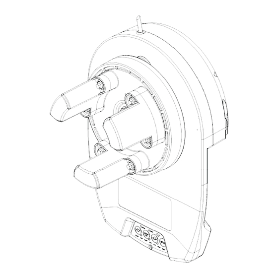
Page 6: Kit Contents
4. Kit Contents REGISTRATION CARD Fig.4.1 4.1 Kit Contents ITEM DESCRIPTION GDO-12 POWER DRIVE UNIT JANUS INTERNAL GEAR ADAPTOR HEX SERRATION HEAD SCREW M6 X 20 SAFETY BEAM KIT PREMIUM WALL CONTROL REMOTE CONTROL TRANSMITTER LOCKING BAR COVERS GUIDE PACK VR12 SCREW-EYE PLASTIC WALL PLUG 6.9 X 25 (1”) ALTERNATIVE FORKS... -
Page 7: Operator Safety & Security
© Copyright 2019 5. Operator Safety & Security 5.1 Your Door CAN NOT be used by the opener when: MANUAL RELEASE a. There is a locking device installed. b. There is a power failure. 5.2 Your Door CAN be used when: WARNING! When operating the manual a. -
Page 8: Installation Instructions
6. Installation Instructions IMPORTANT INSTALLATION INSTRUCTIONS. WARNING - To reduce the risk of severe injury or death: (1) READ AND FOLLOW ALL INSTALLATION INSTRUCTIONS. (2) Install only on a properly operating and balanced sheet door. An improperly balanced door has the potential to inflict severe injury. -
Page 9: Pre-Installation Requirements
© Copyright 2019 6.1 Pre-Installation Requirements WARNING! It is vital for the safety of persons to follow all instructions. Failure to comply with the installation instructions and the safety warnings may result in serious personal injury and/or property and remote control opener damage. AVERTISSEMENT! pour la sécurité... -
Page 10: Door Preparation
6.2 Door Preparation 6.2.1 Preparation a. Check the door’s operation: The door must travel smoothly and be easy to operate by hand. Adjust any tight or twisted guides. iii. Clean the guides if there is any oil or wax present using a suitable white spirit. The only lubricant suitable for use on door guides is silicon spray. -
Page 11: Fitting The Opener
© Copyright 2019 6.3 Fitting the Opener 6.3.1 Mounting The Opener a. Check the drive gear rotates freely, by pulling the string handle down (there will be a click) to disengage opener. Then move the forks from side to side by hand b. -
Page 12: Safety Beam Installation
6.4 Safety Beam Installation IMPORTANT NOTE: The Safety Beam must be installed and connected before the travel limits are set. ATTENTION: Le faisceau de sécurité doit être installé et connecté avant de définir les fins de course. 6.4.1 Safety Infra-Red Beam Kit (P/N 62047) A Safety Beam extends across the door opening. -
Page 13: Setting Speed And Limits
S T E P O N E S T E P T W O © Copyright 2019 If Close speed not suitable, release button, THEN 6.5 Setting Speed and Limits HOLD HOLD Each press Take note of the speed as changes speed 6.5.1 Set the Limit Positions and adjust drive speed: door moves... -
Page 14: Clearing The Door Limit Positions
6.5 Setting Speed and Limits NOTE: If unhappy with the speed or travel limit setting, restart this procedure by clearing the door limit positions as per below first. 6.5.2 Clearing the Door Limit Positions 6.5.3 Re-profiling the Door C L E A R I N G T H E D O O R L I M I T P O S I T I O N S R E - P R O F I L I N G T H E D O O R Re-pro ling is a simple way of re-learning the travel S T E P O N E... -
Page 15: Safety Testing & Accessories
© Copyright 2019 6.7 Safety Testing & Accessories HELPFUL TIP: To conduct safety testing with ease CAUTION: Take care when testing the safety obstruction force. Excessive force may cause serious personal injury and/or property precode a remote control button first. Refer to coding transmitters in next section. -
Page 16: Coding Transmitters
6.8 Coding Transmitters TRANSMITTERS COMPLIANCE STATEMENT TRANSMITTERS COMPLY WITH ALL UNITED STATES AND CANADIAN LEGAL REQUIREMENTS AS OF THE DATE OF MANUFACTURE. TO COMPLY WITH FCC PART 15 AND OR RSS 210 INNOVATION, SCIENCE AND ECONOMIC DEVELOPMENT CANADA RULES, ADJUSTMENT OR MODIFICATIONS OF THIS RECEIVER AND / OR TRANSMITTER ARE PROHIBITED, EXCEPT FOR CHANGING THE CODE SETTING OR REPLACING THE BATTERY. -
Page 17: Remote Control Transmitter Button To Operate Door
controls cover CODE LED is lit © Copyright 2019 S T E P T H R E E 6.8 Coding Transmitters till all three LED’s are lit Press repeatedly 6.8.1 Remote Control Transmitter Button to Operate Door S T E P F O U R S T E P F I V E The opener can only be operated from remote 6.8.3 Selecting The Function To Be Coded... -
Page 18: Attach Warning Labels
DESCRIPTION MATERIAL PART# PROPRIETARY AND CONFIDENTIAL PROPRIETARY AND CONFIDENTIAL Automatic Technology Australia Pty Ltd. THE INFORMATION CONTAINED IN THIS DRAWING IS THE SOLE PROPERTY OF 6-8 FIVEWAYS BOULEVARD, KEYSBOROUGH, VIC, 3173, AUSTRALIA AUTOMATIC TECHNOLOGY AUSTRALIA Pty Ltd. ANY REPRODUCTION IN PART OR AS A WHOLE... -
Page 19: Operation Instructions
© Copyright 2019 7. Operation Instructions IMPORTANT SAFETY INSTRUCTIONS WARNING! TO REDUCE THE RISK OF SEVERE INJURY OR DEATH: (1) READ AND FOLLOW ALL INSTALLATION INSTRUCTIONS. (2) NEVER LET CHILDREN OPERATE OR PLAY WITH DOOR CONTROLS. KEEP THE REMOTE CONTROL AWAY FROM CHILDREN. (3) ALWAYS KEEP THE MOVING DOOR IN SIGHT AND AWAY FROM PEOPLE AND OBJECTS UNTIL IT IS COMPLETELY CLOSED. -
Page 20: How To Use Your Operator
7.1 How to Use Your Operator For maximum efficiency of your operator, your garage door must be in good operating condition. An annual service of your garage door by door professional is recommended. CAUTION: Activate the operator only when the WARNING! This operator has a grounding type plug door is in full view, free of obstructions and with the and there are no user serviceable parts inside this... -
Page 21: User Operating Controls
© Copyright 2019 7.2 User Operating Controls Button Function 1. BLUE DOWN ARROW Close Button 2. RED STOP/SET Stop / Set Button 3. GREEN UP ARROW Open Button 4. MODE Mode Selection Button 7.3 Door Status Indicators Door Status Indicators OPEN LED (green) CLOSE LED (blue) STOP (red) -
Page 22: Disposal Of Batteries
7.4 Disposal of Batteries 7.4.1 Correct Disposal of Batteries: Button Batteries contain toxic materials and should never be disposed of in the trash WARNING! Button cell lithium batteries MUST have their battery terminals covered BEFORE placing them in the box for shipping. -
Page 23: User Maintenance Instruction
© Copyright 2019 8. User Maintenance Instruction WARNING! Safety Testing procedures CAUTION: Frequently examine the installation, in MONTHLY in Section 6.8 to ensure garage door is fit particular cables, springs and mountings, for signs of for use. wear, damage or imbalance. DO NOT USE if repair or adjustment is needed since a fault in the installation or an AVERTISSEMENT! Appliquez les procédures de test de incorrectly balanced door may cause injury. -
Page 24: Troubleshooting
9. Troubleshooting Symptom Possible cause Remedy The opener does not work Garage door in poor condition e.g. springs may Check the door’s operation - see monthly maintenance from the Remote Control be broken (Section 8) Transmitter The opener does not have power Plug a device of similar voltage (e.g. -
Page 25: Appendix
© Copyright 2019 10. Appendix A - Adjustment Mode Parameters A D J U S T M E N T M O D E I N S T R U C T I O N S S T E P O N E Remove controls cover One of the word LED’s till Spanner... -
Page 26: B - Setting The Pet Mode Position
S E T T I N G T H E P E T M O D E P O S I T I O N When activated, PET mode drives the door to a B - Setting the PET Mode position preset position from the close position, therefore allowing a pet or parcel to go under the door. -
Page 27: D - Setting Limits Via Transmitter
© Copyright 2019 D - Setting Limits via Transmitter The Dominator Hiro has the ability to set travel limits using a transmitter, allowing free movement around the garage to better assess the desired limit positions. In order to use a transmitter, it must first have at least one of its buttons coded to the shutter controller. The function assigned to the transmitter’s buttons is of no concern here as the buttons are temporally assigned to OPEN, SET, CHANGE DIRECTION and CLOSE (Fig. -
Page 28: E - Additional Remote Control Functions
Press to test coding buttons Release both buttons Press, then HOLD for 4 sec RELEASE try another remote Automatic Technology America 3626 North Hall Street, Suite 610, Dallas, TX 75219, United States of America P: +1 800 934 9892 W: www.ata-america.com...
Need help?
Do you have a question about the GDO-12 HiRO GDO-12V1AM and is the answer not in the manual?
Questions and answers