Brother TD-2020 Service Manual
Hide thumbs
Also See for TD-2020:
- User manual (122 pages) ,
- Quick refence manual (2 pages) ,
- Reference manual (49 pages)
Table of Contents
Advertisement
Quick Links
Advertisement
Table of Contents
Troubleshooting

Related Manuals for Brother TD-2020


Summary of Contents for Brother TD-2020
- Page 1 SERVICE MANUAL MODEL: TD-2020/2120N/2130N...
- Page 2 PREFACE This publication is a service manual covering the specifications, theory of operation, disassembly/reassembly procedure, and troubleshooting the Brother TD-2020/2120N/2130N. It is intended for service personnel and other concerned persons to accurately and quickly provide after- sale service for our TD-2020/2120N/2130N.
-
Page 3: Table Of Contents
CONTENTS CHAPTER I SPECIFICATIONS 1.1 MECHANICAL SPECIFICATIONS..................I-1 1.1.1 External Appearance ......................I-1 1.1.2 Operational Panel ........................I-2 1.1.3 Printing Mechanism......................I-2 1.1.4 Media Specification......................I-2 1.1.5 Cutter ...........................I-2 1.1.6 Interface..........................I-3 1.1.7 Supported OS........................I-3 1.2 ELECTRONICS SPECIFICATIONS ..................I-4 1.2.1 Power Supply (Optional).....................I-4 1.2.2 Main PCB ..........................I-4 CHAPTER II THEORY OF OPERATION 2.1 OUTLINE OF MECHANISMS .................... - Page 4 3.5 ASSEMBLY PROCEDURE ....................III-26 [ 1 ] Assembling the Mecha ASSY ..................III-26 [ 2 ] Attaching the Adjuster Rack L/R and Adjuster Gear..........III-28 [ 3 ] Assembling the Movable Sensor PCB ASSY ............. III-30 [ 4 ] Attaching the Cover Open Sensor and Movable Sensor PCB ASSY ......III-31 [ 5 ] Attaching the Upper Cover..................
- Page 5 1.2.11Adjust Transmission Sensor ..................... 1-14 1.2.12Adjust Reflection Sensor....................1-17 1.2.13Reboot Printer........................1-20 1.2.14Print Test (Label)......................1-21 1.2.15Check Adaptor AD ......................1-23 1.2.16Check USB Host....................... 1-24 1.2.17Check Connect TDU ......................1-25 1.2.18Check Peel Sensor (Paper none)..................1-26 1.2.19Check Peel Sensor (Paper on) ..................1-27 1.2.20Check Battery A/D ......................
-
Page 6: Chapter I Specifications
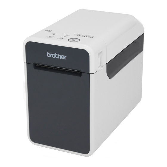
CHAPTER I SPECIFICATIONS 1.1 MECHANICAL SPECIFICATIONS 1.1.1 External Appearance (1) Dimensions (W x D x H) 110mm x 215mm x 171.5mm (2) Weight Approx. 1340g (Printer) <Upper side> 215mm <Front side> 171.5mm 110mm Figure 1.1-1 External Appearance I - 1... -
Page 7: Operational Panel
(2) Highest printing speed 152.4mm/sec (6 ips) (3) Print head - Type Thick film thermal head TD-2020/2120N: 448 dots by one row TD-2130N: 672 dots by one row - Resolution TD-2020/2120N: 203 dpi TD-2130N: 300 dpi 1.1.4... -
Page 8: Interface
PA-WI-001 mounted (only TD-2120N/2130N) (5) USB HOST For barcode reader or for WLAN option (6) Ethernet 10/100 base-TX Ethernet (only TD-2120N/2130N) 1.1.7 Supported OS TD-2020: Microsoft Windows XP Microsoft Windows Vista Microsoft Windows 7 Microsoft Windows 8 TD-2120N/2130N: Microsoft Windows XP... -
Page 9: Electronics Specifications
1.2 ELECTRONICS SPECIFICATIONS 1.2.1 Power Supply (Optional) (1) Battery Rechargeable Li-ion battery: 14.4V (2) Battery Yield Continuously printing 2000 labels (* Under Brother standard environment) (3) Adapter AC adapter (25V) 1.2.2 Main PCB (1) Block Diagram RJ45 Ethernet Flash ROM... -
Page 10: Chapter Ii Theory Of Operation
(TD-2020/2120N) or 672 pieces (TD-2130N) of heating elements arrayed in vertical single row as shown in the Figure 2.1-1. The dimension of each heating element is vertical length 0.11 (TD-2020/2120N) or 0.07 (TD-2130N) (0.125mm pitch (TD-2020/2120N) or 0.0847mm pitch (TD-2130N)) x horizontal width 0.132mm (TD-2020/2120N) or 0.11mm (TD-2130N). -
Page 11: Press Contact And Release Mechanism Of Thermal Head
2.1.2 Press Contact and Release Mechanism of Thermal Head The head ASSY is pressed firmly against the platen roller by the force of the head spring. When the release lever is lifted, the lock of the release lever is unlocked so that the roll cover is released. -
Page 12: Tape Feed Mechanism
2.1.3 Tape Feed Mechanism When the tape is fed, it is caught between the platen roller and the head ASSY, and is eventually pressed against the head ASSY. This rotates the tape feed motor ASSY, and its drive power is transmitted to the platen gear and the platen roller via the gear train, and consequently the platen feeds the tape. -
Page 13: Cover Open Sensor
2.1.4 Cover Open Sensor The cover open sensor is mounted in the upper cover. By closing the roll cover, section “A” of the roll cover inner presses the switch of the cover open sensor, and transmits the “roll cover closed” signal. Roll cover Section “A”... -
Page 14: Lock And Release Of Adjuster Rack
2.1.5 Lock and Release of Adjuster Rack To release the adjuster lock tab from the gear of the upper cover, lift the adjuster lock of the adjuster rack R. It allows adjuster rack gears L/R to move to left and right. To lock the adjuster lock tab to the gear of the upper cover and fix the width, release the adjuster lock. -
Page 15: Chapter Iii Disassembly And Reassembly
CHAPTER III DISASSEMBLY AND REASSEMBLY 3.1 SAFETY PRECAUTIONS (1) The disassembly or reassembly work should be carried on a grounded antistatic sheet. Otherwise, the LSIs and electronic parts may be damaged due to the electricity charged in your body. (2) When transporting PCBs, be sure to wrap them in conductive sheets such as aluminum foil. -
Page 16: Lubrication Points List
3.3 LUBRICATION POINTS LIST Apply Silicon grease G501 (4mm size) on the mating teeth surface of the platen gear and the double gear C. Platen gear Apply Silicon grease G501 (4mm size) on the two places of the mating teeth surface of the double Apply Silicon grease gear B and the double gear A. -
Page 17: Disassembly Procedure
3.4 DISASSEMBLY PROCEDURE [ 1 ] Preparation (1) Press the power button to turn OFF the main power switch. (2) Disconnect all cables connected to the machine. (3) Lift the release lever to open the roll cover ASSY. Remove the thermal tape and close the roll cover ASSY. -
Page 18: 2 ] Removing The Bottom Cover B, Front Cover, And Bottom Cover A
[ 2 ] Removing the Bottom Cover B, Front Cover, and Bottom Cover A (1) Turn the machine upside down. (2) Remove the four taptite bind B M2.6X6 screws to remove the bottom cover B from the machine. (3) Remove the four taptite bind B M2.6X8 screws from the bottom cover A. Taptite bind B M2.6X6 Bottom cover B Taptite bind B M2.6X8... - Page 19 (4) Turn the machine upside down. (5) Lift the release lever to open the roll cover ASSY. (6) Remove the two taptite bind B M2.6X8 screws from the front cover. Push the bottom cover A outward to remove the front cover. Roll cover ASSY Release lever Taptite bind B M2.6X8...
- Page 20 (7) Push the bottom cover A outward to remove it from the machine. Remove the guide shaft from the machine and close the roll cover ASSY. (8) Remove the four lower foots from the bottom cover A. Roll cover ASSY Guide shaft Bottom cover A Lower foots...
-
Page 21: 3 ] Removing The Main Pcb Assy
[ 3 ] Removing the Main PCB ASSY (1) Turn the machine upside down. (2) Remove the two tapes A from the main PCB ASSY and the machine. (3) Disconnect all harnesses connected to main PCB ASSY. (4) Remove the five taptite bind B M2.6X8 screws to remove the main PCB ASSY from the machine. -
Page 22: 4 ] Removing The Pcb Holder
[ 4 ] Removing the PCB Holder (1) Lift the release lever to open the roll cover ASSY, and remove the two taptite bind B M2.6X8 screws. Close the roll cover ASSY and turn the machine upside down. (2) Release each harness from the securing fixture. (3) Remove the two taptite bind B M2.6X8 screws. - Page 23 (4) Turn the machine upside down. NOTE: Roll shaft could drop when the left side of the machine is facing downwards. Be careful not to lose it. (5) Lift the release lever to open the roll cover ASSY. (6) Remove the three roll shafts to remove the nine roll rollers from the machine. Release lever Roll rollers Roll cover ASSY...
-
Page 24: 5 ] Removing The Roll Cover Assy
[ 5 ] Removing the Roll Cover ASSY (1) Release the edge of the damper spring from the damper groove. Remove the retaining ring 2.5 and pull out the damper shaft to remove the damper and the damper spring. (2) Release the edge of the damper spring 2 from the damper groove. Remove the retaining ring 2.5 and pull out the damper shaft to remove the damper and the damper spring 2. -
Page 25: 6 ] Removing The Roll Sponge L/R
[ 6 ] Removing the Roll Sponge L/R (1) Remove the roll sponge L and roll sponge R from the roll cover inner. Roll sponge R Roll sponge L Roll cover inner Figure 3.4-9 III - 11... -
Page 26: 7 ] Removing The Roll Cover Outer A
[ 7 ] Removing the Roll Cover Outer A (1) Remove the four taptite bind B M2.6X8 screws to remove the roll cover outer A from the roll cover inner. Taptite bind B M2.6X8 Roll cover inner Roll cover outer A Figure 3.4-10 III - 12... -
Page 27: 8 ] Removing The Roll Cover Front, Roll Cover Clear, And Roll Cover Outer B
[ 8 ] Removing the Roll Cover Front, Roll Cover Clear, and Roll Cover Outer B (1) Remove the four taptite bind B M2.6X8 screws from the back side of the roll cover inner. (2) Remove the six taptite bind B M2.6X8 screws. Lift the roll cover outer B to remove the roll cover front and roll cover clear from the roll cover inner. - Page 28 (3) Remove the filament tape 3M #893. (4) Pull out each harness from the hole of the roll cover inner and release them from the securing fixtures. (5) Turn over the roll cover outer B. (6) Remove the two taptite bind B M2.6X8 screws to remove the FG harness ASSY. Release the hook to remove the panel PCB ASSY from the roll cover outer B.
-
Page 29: 9 ] Removing The Tear Bar And Release Lever Assy
[ 9 ] Removing the Tear Bar and Release Lever ASSY (1) Remove the two taptite bind B M2.6X6 screws, and remove the tear bar from the roll cover inner. Remove the tear bar cap from the tear bar. (2) Turn the release lever ASSY in the direction of the arrow to remove it from the two shaft bushings of the roll cover inner. -
Page 30: 10 ]Removing The Head Holder B And Head Spring
[ 10 ]Removing the Head Holder B and Head Spring (1) Remove the four taptite bind B M2.6X6 screws, and remove the head holder B and the two head springs from the roll cover inner. Taptite bind B M2.6X6 Head holder B Head springs Roll cover inner Figure 3.4-14... -
Page 31: 11 ] Removing The Sensor Holder B, T Sensor Pcb Assy, And Sensor Cover C
[ 11 ] Removing the Sensor Holder B, T Sensor PCB ASSY, and Sensor Cover C (1) Turn over the roll cover inner. (2) Remove the two taptite bind B M2.6X8 screws, and remove the sensor holder B from the roll cover inner. Pull out the harness of T sensor PCB ASSY from the hole of the roll cover inner. -
Page 32: 12 ]Removing The Head Assy
[ 12 ]Removing the Head ASSY (1) Pull up the head ASSY while pushing it in the direction of the arrow. Remove the head ASSY and the head spring B from the roll cover inner, and pull out the two head harnesses and the FG harness ASSY from the two holes of the roll cover inner. -
Page 33: 13 ]Removing The Upper Cover
[ 13 ]Removing the Upper Cover (1) Remove the four taptite bind B M2.6X8 screws. Release the two hooks to remove the upper cover from the mecha ASSY. Upper cover Hooks Taptite bind B M2.6X8 Mecha ASSY Taptite bind B M2.6X8 Taptite bind B M2.6X8 Figure 3.4-17 III - 19... -
Page 34: 14 ]Removing The Cover Open Sensor And Movable Sensor Pcb Assy
[ 14 ]Removing the Cover Open Sensor and Movable Sensor PCB ASSY (1) Remove the taptite bind B M2.6X6 screw to remove the SW hold plate and the cover open sensor from the upper cover. (2) Slide the movable sensor PCB ASSY in the direction of the arrow, and remove it by aligning its four tabs to four notches on the upper cover. -
Page 35: 15 ]Disassembling The Movable Sensor Pcb Assy
[ 15 ]Disassembling the Movable Sensor PCB ASSY (1) Release the two hooks to remove the sensor holder A from the sensor holder A2. (2) Remove the sensor cover from the sensor holder A. (3) Remove the RT sensor PCB ASSY from the sensor holder A2, and pull out the harness of the RT sensor PCB ASSY from the hole of the sensor holder A2. -
Page 36: 16 ]Removing The Adjuster Gear And Adjuster Rack L/R
[ 16 ]Removing the Adjuster Gear and Adjuster Rack L/R (1) Remove the taptite cup B M2.6X6 screw to remove the adjuster gear from the upper cover. (2) Remove the five PStaite M2X4 CH screws to remove the two guide holders from the upper cover. - Page 37 (3) Remove the adjuster rack L and the adjuster rack R from the upper cover. (4) Secure the roller guide roller firmly, and remove the taptite cup B M2.6X6 screw, and remove the roller guide roller from the adjuster rack R. Remove the two taptite cup B M2.6X6 screws, and remove the adjuster lock and adjuster lock spring from the adjuster rack R while pulling the adjuster lock upward.
-
Page 38: 17 ]Disassembling The Mecha Assy
[ 17 ]Disassembling the Mecha ASSY (1) Release the hook to remove the double gear C and double gear B from the main chassis ASSY. (2) Remove the platen gear from the platen roller. (3) Remove the retaining ring E2.5 to remove the double gear A from the main chassis ASSY. - Page 39 (5) Remove the two filament tapes from the main chassis R and the main chassis ASSY. (6) Remove the two screw bind M3X4 screws to remove the main chassis ASSY and platen roller from the sub plate. Remove the screw bind M2X3 screw to remove the platen bushing L from the main chassis ASSY.
-
Page 40: Assembly Procedure
3.5 ASSEMBLY PROCEDURE [ 1 ] Assembling the Mecha ASSY (1) Attach the front cover B to the sub plate with the two screw bind M3X4 screws. (2) Attach the platen bushing R to the main chassis R with the screw bind M2X3 screw. NOTE: When tightening the screw, push the platen bushing R in the direction of the arrow A to reduce rattle. - Page 41 (8) Attach the tape feed motor ASSY to the main chassis ASSY with the two screw bind M3X4 screws. (9) Set the double gear A to the double gear A shaft on the main chassis ASSY, and secure it with the retaining ring E2.5. (10) Set the double gear B to the double gear B shaft on the main chassis ASSY.
-
Page 42: 2 ] Attaching The Adjuster Rack L/R And Adjuster Gear
[ 2 ] Attaching the Adjuster Rack L/R and Adjuster Gear (1) Attach the film spring 2 as described in the figure below. (2) Secure the roller guide roller firmly, and attach the roller guide roller to the adjuster rack L with the taptite cup B M2.6X6 screw. Stick the film spring to the adjuster rack L. - Page 43 (6) Set the two guide holders to the adjuster rack L and the adjuster rack R, and secure them with the five PStaite M2X4 CH screws. (7) Pull the adjuster rack L and the adjuster rack R outward. Attach the adjuster gear to the upper cover with the taptite cup B M2.6X6 screw.
-
Page 44: 3 ] Assembling The Movable Sensor Pcb Assy
[ 3 ] Assembling the Movable Sensor PCB ASSY (1) Set the sensor plate to the sensor holder A2, and engage the latch. (2) Set the RT sensor PCB ASSY to the sensor holder A2. (3) Attach the sensor cover to the sensor holder A. (4) Set the sensor holder A to the sensor holder A2, and secure it with the two hooks. -
Page 45: 4 ] Attaching The Cover Open Sensor And Movable Sensor Pcb Assy
[ 4 ] Attaching the Cover Open Sensor and Movable Sensor PCB ASSY (1) Set the cover open sensor and SW hold plate to the upper cover, and secure it with the taptite bind B M2.6X6 screw. (2) Set four tabs on the movable sensor PCB ASSY to four notches on the upper cover, and slide the movable sensor PCB ASSY so that the marking is aligned to the one on the upper cover. -
Page 46: 5 ] Attaching The Upper Cover
[ 5 ] Attaching the Upper Cover (1) Set the upper cover to the mecha ASSY. Engage the two hooks and secure them with four taptite bind B M2.6X8 screws. Upper cover Hooks Taptite bind B M2.6X8 Mecha ASSY Taptite bind B M2.6X8 Taptite bind B M2.6X8 Figure 3.5-7 III - 32... -
Page 47: 6 ] Attaching The Head Assy
[ 6 ] Attaching the Head ASSY (1) Stick the peeler sensor tape to the roll cover inner. (TD-2120N/2130N models only) NOTE: Make sure that the tape is attached to three faces, not lifted nor peeled off. (2) Connect the head harness ASSY 1 and head harness ASSY 2 to the head ASSY. (3) Insert the two head harnesses and the FG harness ASSY into the two holes on the roll cover inner. -
Page 48: 7 ] Attaching The Sensor Cover C, T Sensor Pcb Assy, And Sensor Holder B
[ 7 ] Attaching the Sensor Cover C, T Sensor PCB ASSY, and Sensor Holder B (1) Attach the sensor cover C to the sensor holder B. (2) Attach the T sensor PCB ASSY to the sensor holder B using two double face tapes TD2000. -
Page 49: 8 ] Attaching The Head Spring And Head Holder B
[ 8 ] Attaching the Head Spring and Head Holder B (1) Set the two head springs between the bosses of the head holder B and the head sub plate. Set the head holder B to the roll cover inner, and secure it with the four taptite bind B M2.6X6 screws. -
Page 50: 9 ] Attaching The Release Lever Assy And Tear Bar
[ 9 ] Attaching the Release Lever ASSY and Tear Bar (1) Engage edge of the release spring to the hole of the shaft bushing of the roll cover inner, and set the release lever ASSY to the two shaft bushings. NOTE: Be careful not to scratch roll cover inner with the edge of the release spring. -
Page 51: 10 ]Attaching The Roll Cover Outer B, Roll Cover Clear, And Roll Cover Front
[ 10 ]Attaching the Roll Cover Outer B, Roll Cover Clear, and Roll Cover Front (1) Set the button A, button B, status button, and two LED lenses to the roll cover outer B. (2) Set the panel PCB ASSY to the roll cover outer B and secure it with the hook. (3) Secure the panel PCB ASSY and the FG harness ASSY to the roll cover outer B with two taptite bind B M2.6X8 screws. - Page 52 (4) Secure each harness with the securing fixtures. (5) Secure the head harness ASSY 1, panel PCB harness, and FG harness ASSY with the filament tape 3M #893 (W: 9mm X L: 35 ± 5mm). Hole Hole Roll cover inner Guide Guide Panel PCB harness...
- Page 53 (6) Set the roll cover clear to the roll cover inner, and secure it with four taptite bind B M2.6X8 screws. (7) Set the roll cover front and the roll cover outer B to the roll cover inner, and secure them with six taptite bind B M2.6X8 screws. NOTE: Use two screws for front side and four screws for back side.
-
Page 54: 11 ] Attaching The Roll Cover Outer A
[ 11 ] Attaching the Roll Cover Outer A (1) Set the roll cover outer A to the roll cover inner, and secure it with four taptite bind B M2.6X8 screws. Taptite bind B M2.6X8 Roll cover inner Roll cover outer A Figure 3.5-15 III - 40... -
Page 55: 12 ]Attaching The Roll Sponge L/R
[ 12 ]Attaching the Roll Sponge L/R (1) Stick the roll sponge L and roll sponge R to the roll cover inner. Roll sponge R Roll sponge L Roll cover inner Roll sponge R Roll sponge L Figure 3.5-16 III - 41... -
Page 56: 13 ]Attaching The Roll Cover Assy
[ 13 ]Attaching the Roll Cover ASSY (1) Insert each harness into the two holes of the machine, and set the roll cover ASSY to the machine. (2) Align the cut surface and set the damper shaft to the machine. Align edge A of the damper spring to the groove of the machine, and set it to the damper shaft. -
Page 57: 14 ]Attaching The Pcb Holder
[ 14 ]Attaching the PCB Holder (1) Set the three roll rollers to the roll shaft while inserting it to the machine (3 places). Roll rollers Roll shafts Figure 3.5-18 III - 43... - Page 58 (2) Close the roll cover ASSY and turn the machine upside down. NOTE: Roll shaft could drop when the left side of the machine is facing downwards. Be careful not to lose it. (3) Insert each harness into the two holes of the PCB holder. Set the PCB holder to the machine and secure it with two taptite bind B M2.6X8 screws.
- Page 59 (5) Secure each harness with the securing fixture. NOTE: Be sure to slacken the harness by using round bar as described in the figure below. Harness Harness Slit Slit Round bar Figure 3.5-20 III - 45...
-
Page 60: 15 ]Attaching The Main Pcb Assy
[ 15 ]Attaching the Main PCB ASSY (1) Stick tape A (W: 9mm X L: 110 ± 5mm) to the main PCB ASSY so that it covers the PCB's edge. (2) Stick tape B (W: 24mm X L: 80 ± 5mm) to the main PCB ASSY so that it covers the connector foot. - Page 61 (4) Connect each harness to the main PCB ASSY. (5) Attach the main PCB ASSY to the machine by sticking two sheets of tape C (W: 9mm) so that the harnesses are blocked in. Cover open sensor harness Head harness ASSY 2 (BL) RT sensor harness Tape feed...
-
Page 62: 16 ]Attaching The Bottom Cover A, Front Cover, And Bottom Cover B
[ 16 ]Attaching the Bottom Cover A, Front Cover, and Bottom Cover B (1) Attach the four lower foots to the bottom cover A. (2) Lift the release lever to open the roll cover ASSY. (3) Insert the guide shaft into the machine. (4) Set the bottom cover A to the machine by pushing it outward. - Page 63 (5) Set the front cover to the machine by pushing the bottom cover A outward, and secure it with two taptite bind B M2.6X8 screws. (6) Close the roll cover ASSY. Roll cover ASSY Taptite bind B M2.6X8 Front cover Bottom cover A Figure 3.5-24 III - 49...
- Page 64 (7) Turn the machine upside down. (8) Tighten four taptite bind B M2.6X8 screws to the machine. (9) Set the bottom cover B to the machine, and secure it with four taptite bind B M2.6X6 screws. Taptite bind B M2.6X6 Bottom cover B Taptite bind B M2.6X8 Taptite bind B M2.6X8...
-
Page 65: 17 ]Demonstration Print And Final Check
(3) Press and hold the Print button until the POWER indicator starts blinking in green. Demonstration print will be printed. Total pages printed at the time of the error <TD-2020> Error log Total pages printed at the time of the error <TD-2120N>... - Page 66 <Error log> Error information (error code and total pages printed at the time of the error) are logged in the event of following errors. The latest error information is printed after “#01=”. The previous error is printed after “#02=”. Error information log can be stored up to 10 errors. The oldest error information will be removed when the new error information is added.
-
Page 67: Chapter Iv Troubleshooting And Error Message
CHAPTER IV TROUBLESHOOTING AND ERROR MESSAGE This section gives the service personnel some of the troubleshooting procedures to be followed if an error or malfunction occurs with this machine. It is impossible to anticipate all of the possible troubles which may occur in future and determine the troubleshooting procedures, so this chapter covers some sample troubles. -
Page 68: Troubleshooting Flows
4.3 TROUBLESHOOTING FLOWS [ 1 ] Printing is performed with specific dots omitted. Printing is performed with specific dots omitted. The thermal head and the platen are dirty. Are the thermal head and the platen dirty? Clean the thermal head and the platen. -
Page 69: 2 ] The Power Supply Does Not Turn On
[ 2 ] The power supply does not turn ON. The power supply does not turn ON. Is the cable of AC power supply or battery Correct the connection. connected correctly? Turn ON the main power switch. Is the main power switch ON? Are all harnesses Correct the connection. -
Page 70: 3 ] No Printing Is Performed
[ 3 ] No printing is performed. Tape feed is normal but cannot print. Is the direction Set the roll in the correct of the roll correctly? direction. Is the print head Correct the connection. cable connected correctly? If replace the main PCB ASSY, The main PCB is defective. -
Page 71: 4 ] The Usb Interface Malfunction
[ 4 ] The USB interface malfunction. The interface malfunction. Is the USB cable Correct the connection. connected correctly? Are the printer driver Re-install the driver and editor and P-touch editor installed correctly. onto the PC correctly? Is the port set to USB Set to USB port. -
Page 72: 5 ] The Ethernet Interface Malfunction
[ 5 ] The Ethernet interface malfunction. * Except for TD-2020 The interface malfunction. Is the Ethernet cable Correct the connection. connected correctly? Are the printer driver Re-install the driver and editor and P-touch editor installed correctly. onto the PC correctly? Is the port set to Ethernet Set to Ethernet port. -
Page 73: 6 ] The Rs232C Interface Malfunction
[ 6 ] The RS232C interface malfunction. The interface malfunction. Is the RS232C cable Correct the connection. connected correctly? Is the interlink cable Use the interlink cable. (cross) used? Are the printer driver Re-install the driver and editor and P-touch editor installed correctly. -
Page 74: 7 ] The Bluetooth/Wi-Fi Interface Malfunction
[ 7 ] The Bluetooth/Wi-Fi interface malfunction. * Except for TD-2020 The interface malfunction. Is the interface cable Correct the connection. connected correctly? Is the slide SW ON? Turn it ON. Is the Wi-Fi/BT Optional component is defective. LED lit in orange? Replace it with a new one. -
Page 75: 8 ] The Paper Is Not Fed Correctly
[ 8 ] The paper is not fed correctly. The paper feed is not correctly. Try to print after replace a new paper (roll). Repair completed. Is tape feed normal? The old thermal tape is defective. Is the paper passed upper the insert guide? Insert the paper Is the paper set at the... -
Page 76: Appendix 1 Serviceman Software Tool
APPENDIX 1 SERVICEMAN SOFTWARE TOOL 1.1 Introduction 1.1.1 Software Tools In addition to the primary serviceman tool, the buffer analysis tool is also equipped for TD- 20220/2120N/2130N. Implement each tool as usage. • Serviceman tool This tool is used to change EEPROM setting and check functions after machine repair or PCB replacement. -
Page 77: Serviceman Tool
Note that separate inspections are required for each of them as needed. This tool supports: • TD-2020 (hereinafter referred to as "TD-2000") • TD-2120N / 2130N (hereinafter collectively referred to as "TD-2100N"). Models and the corresponding tools are described in the table below. Inspections are inoperable with wrong combination. -
Page 78: Inspection Outline
1.2.2 Inspection Outline When you start the tool and implement "Read serial no", the next available inspection, "Write default eeprom data", becomes operable after completion of the inspection. All the listed inspections will be completed by operating in descending order. Inspections after "Check adaptor AD"... -
Page 79: How To Start The Serviceman Tool
1.2.3 How to Start the Serviceman Tool Select [SE] > [ProductChkTool.exe] to start the serviceman tool. Note : Be sure to store all pre-included setting files (e.g. ".ini", ".prn", and ".bin" files) in the same folder with the execution file "ProductCheck.exe". The tool is inoperable without the file. - Page 80 Make sure that the machine is connected to the PC, and then click [Run] button on the main window. The inspection item currently selected (yellow background) will be implemented. To change the selected inspection, press the [Down] or [Up] button. When all required inspection items are completed, click the [To next check] button to proceed to the next inspection.
-
Page 81: Read Serial No
1.2.4 Read Serial No Enter the serial number printed on the rating plate which is attached on the back of the machine. Entering serial number initializes the EEPROM in the machine, and initializing the EEPROM clears the serial number. Serial number will not be written in this process. Implement "Write serial no" at the end of all inspections. - Page 82 No" window. Check if the latest available version of ModelCheck.ini file is displayed. If older version is displayed, incompatible model code will be NG on the inspection. Figure 5. "Model Info" field TD-2020 - latest version 1.02 Model Model Code...
- Page 83 Inspection errors • Can not connect. The following error occurs when the machine is not connected with PC. Check that the machine is connected to the PC properly and the machine is turned ON. Figure 7. Can not connect. •...
-
Page 84: Read Mac Address
1.2.5 Read MAC Address Acquires Wired LAN MAC address retained in EEPROM. Model Inspection TD-2000 Invalid TD-2100N Valid This inspection starts automatically when the previous inspection is completed. When operating this inspection again, check that the "Check Mac address" field is highlighted in yellow, then press the [Run] button. -
Page 85: Write Default Eeprom Data
1.2.6 Write Default EEPROM Data Writes default settings by model and destination into EEPROM of the machine. Model Inspection TD-2000 Valid TD-2100N Valid This inspection starts automatically when the previous inspection is completed. When operating this inspection again, check that the "Write default eeprom data" field is highlighted in yellow, then press the [Run] button. -
Page 86: Write Product Information
[Run] button. Writing result (TD-2130N) Figure 14. "Write product info" Write values for each model are shown below. Product ID/String Model Parameter Write value TD-2020 Product id 2055 Product string TD-2020 TD-2120N Product id 2057... -
Page 87: Write Mass Storage Information
[Run] button. Writing result (TD-2130N) Figure 15. "Write mass storage info" Write values for each model are shown below. Product ID/String Model Parameter Write value TD-2020 Product id 2059 Product string TD-2020 TD-2120N Product id 205B... -
Page 88: 10Write Pin Code And Local Name
1.2.10 Write PIN Code and Local Name Writes unique PIN code and local name used for Bluetooth connection into the machine. Model Inspection TD-2000 Invalid TD-2100N Valid Writing local name starts automatically when the previous inspection is completed. When operating this inspection again, check that the "Write pincode and localname" field is highlighted in yellow, then press the [Run] button. -
Page 89: 11Adjust Transmission Sensor
1.2.11 Adjust Transmission Sensor Adjusts sensor read value to allow transmission sensor to detect label and separator. Also checks cover sensor function when the cover is opened or closed. 80GS OJI roll ASSY must be used for sensor adjustment. Cut the media in advance as it is wider than the machine. Also, make sure that the sensor is positioned properly. - Page 90 Check that the separator jig set in the sensor read section on the machine is matched with the image displayed on the "Adjust transmission sensor" window. → If matched, step to the next. → If not matched, hold down the [NG] button to stop the inspection. Figure 19.
- Page 91 When the adjustment is completed, the display below appears. As soon as "OK" appears in the "Result" field, "Photo sensor adjust is OK. Please open cover." appears in the "Status" field. Open the cover. → When "NG" appears in the "Result" field, the instruction to open the cover does not appear in the "Status"...
-
Page 92: 12Adjust Reflection Sensor
1.2.12 Adjust Reflection Sensor Adjusts sensor read value to allow reflection sensor to detect media. Also checks cover sensor function when the cover is opened or closed. Only the paper for reflection sensor adjustment is allowed to use. Cut the media in advance as it is wider than the machine. Note : Peel the label off from the media prior to the inspection. - Page 93 The adjustment screen appears once the inspection starts. Figure 24. "Adjust photo sensors" window If the cover of the machine is open at that time, the "Adjust photo sensors" window is closed automatically and the inspection ends up as NG. "Cover check error.
- Page 94 Adjustment OK conditions "A/D value" is within 162 to 171. "Duty ratio" is within 30 to 100. Possible cause for adjustment NG • Photo sensor failure • Wrong or worn out adjustment media • The media used are wrong Once "OK"...
-
Page 95: Reboot Printer
1.2.13 Reboot Printer Reboots the machine otherwise some settings will not be applied. Model Inspection TD-2000 Valid TD-2100N Valid Make sure that the "Reboot printer" field is highlighted in yellow and press the [Run] button to start the inspection. Figure 26. "Reboot printer" start-up The message below appears in the "Results"... -
Page 96: Print Test (Label)
1.2.14 Print Test (Label) Checks the print quality as well as result of transmission and reflection sensor. Model Inspection TD-2000 Valid TD-2100N Valid Open the cover of the machine to set the inspection media for RDU F59X102 1 ASSY. Set the media so that it comes out from the ejecting section, and close the cover. - Page 97 Printing pattern for print test (Label) • Printing pattern for 200dpi (TD-2020 / TD-2120N) Reflection sensor Transmission sensor stop position stop position Ejecting direction Figure 30. Printing pattern for 200dpi • Printing pattern for 300dpi (TD-2130N) Reflection sensor Transmission sensor...
-
Page 98: 15Check Adaptor Ad
1.2.15 Check Adaptor AD Inspections after "Check adaptor AD" are optional. However, to check operations of all functions, all inspections are basically necessary. This inspection checks if the voltage and temperature sensor of the head and motor is working normally. Connect the AC adapter (not optional battery base unit) to the machine before implementing this inspection. -
Page 99: Check Usb Host
1.2.16 Check USB Host Checks operation of the USB host. Also checks ability to detect connected USB device when the machine is not connected to the host. On top of those inspections, communication interface with WiFi option (PA-WI-001) will be checked too. Model Inspection TD-2000... -
Page 100: 17Check Connect Tdu
1.2.17 Check Connect TDU Checks communication during the optional touch panel display unit is connected. This inspection also checks the operation of the connector on the optional touch panel display unit connection. For models without optional touch panel display unit, attach the optional touch panel display unit for inspection before implementing the inspection. -
Page 101: 18Check Peel Sensor (Paper None)
1.2.18 Check Peel Sensor (Paper none) Checks that the machine can detect A/D value of the connected optional peeler when no paper is set. This inspection also checks the normal operation of the connector between the machine and optional peeler. For models without optional peeler, remove the cover and attach the optional peeler for inspection first. -
Page 102: 19Check Peel Sensor (Paper On)
1.2.19 Check Peel Sensor (Paper on) Checks that the machine can detect the A/D value of the connected optional peeler when any paper is set. Use the label for RDU F59X102 1 ASSY. Model Inspection TD-2000 Invalid TD-2100N Valid Place the label (peeled from the paper) so that it covers the top of the peel sensor. Make sure that the "Check peel sensor (Paper on)"... -
Page 103: 20Check Battery A/D
1.2.20 Check Battery A/D Checks the A/D value detected by power supply from the battery. This inspection also checks the normal operation of the optional battery base unit connector. For models without optional battery base unit, remove the cover and attach the optional battery base unit for inspection first. Model Inspection TD-2000... -
Page 104: 21Check Holder Adaptor Ad
1.2.21 Check Holder Adaptor AD Checks that the power is supplied normally by connecting the AC adapter to the optional battery base unit. Model Inspection TD-2000 Invalid TD-2100N Valid Connect the AC adapter to the optional battery base unit first, and then remove the Li-ion rechargeable battery. -
Page 105: 22Check Battery Charge
1.2.22 Check Battery Charge Checks that the machine enters the recharging mode by connecting the AC adapter and Li-ion rechargeable battery to the optional battery base unit. Model Inspection TD-2000 Invalid TD-2100N Valid Set the Li-ion rechargeable battery to the optional battery base unit again. Keep connecting the AC adapter to the optional battery base unit while setting it. -
Page 106: Check Led
1.2.23 Check LED Checks that the connector is connected to the optional battery base unit LED properly by visual check on LED color. Also checks that the color of the LED light switches properly. Note : Optional battery base unit LED check is only for TD-2100N. For TD-2000, only LED on the top of the machine is required to check. - Page 107 By pressing the [Feed] key, LED on the machine changes to "LED light pattern 2" shown below. Again, if the LED light pattern on the machine and tool is matched, press the [Print] key on the machine. → If the LED color is different or does not switch by pressing keys, press the [NG] button on the tool screen to finish the inspection.
-
Page 108: 24Write Smart Info
1.2.24 Write Smart Info TD-2130NHC model enters the smart function mode. Other models do not change the mode. * After this inspection, TD-2130NHC model starts feeding by opening/closing the cover. Please not that. Model Inspection TD-2020 Invalid TD-2120N Invalid TD-2130N Valid Check that the "Write smart info"... -
Page 109: 25Write Serial No
1.2.25 Write Serial No Reads firmware version through serial transmission (RS-232C) to write serial number into the machine. For TD-2100N, this inspection also checks the communication interface with Bluetooth option (PA-BI-001). Model Inspection TD-2000 Valid TD-2100N Valid Disconnect the USB cable from the machine. Connect the RS-232C cable and PA-SCA- 001, and connect it to the machine. - Page 110 Changing settings for RS-232C The computer and the machine used in write serial number must be connected with RS- 232C. To connect to the optional COM port of the computer, change the inspection tool settings by following procedures below. Start the inspection tool and press the [General settings] button on the main screen.
- Page 111 A window prompting to save the setting appears. Press the [OK] button. Once the [OK] button is pressed, the settings will be remained even after closing the serviceman tool. Figure 62. Window prompting to save setting The display automatically returns to the previous "Config" window. Press [OK] button to return to the main window.
-
Page 112: Buffer Analysis Tool
1.3 Buffer Analysis Tool 1.3.1 Role of the Buffer Analysis Tool Buffer analysis tool serves to analyze commands sent to the machine. Also serves to output data files sent to the printer buffer while the machine was ON. This is common to TD-2000 and TD-2100N. -
Page 113: Output Buffer Data
1.3.3 Output Buffer Data Outputs data required for the machine analysis as a binary file (*.bin). It can be used when the investigation of the causes for the BIL is needed. Follow the instructions given by serviceman to use this tool properly. Check that the machine is turned ON and connected to the PC with USB cable. - Page 114 Feb., 2013 SM-PT056...
Need help?
Do you have a question about the TD-2020 and is the answer not in the manual?
Questions and answers