Vega VEGAPULS 62 Operating Instructions Manual
Universally implementable radar level transmitter for continuous level 4...20 ma/hartmeasurement of liquids
Hide thumbs
Also See for VEGAPULS 62:
- Operating instructions manual (104 pages) ,
- Quick setup manual (24 pages) ,
- Safety instruction (16 pages)
Table of Contents
Advertisement
Quick Links
Advertisement
Table of Contents

Related Manuals for Vega VEGAPULS 62


Summary of Contents for Vega VEGAPULS 62
- Page 1 Rhein Tech Laboratories Client: Ohmart/VEGA 360 Herndon Parkway Model: VEGAPULS 616263 Suite 1400 FCC ID: MOIPULS616263 Herndon, VA 20170 Standards: FCC 15.209/IC RSS-210 http://www.rheintech.com Report Number: 2004236-62 APPENDIX C: MANUAL Please see the following pages. 17 of 26...
-
Page 2: Operating Instructions
Operating Instructions VEGAPULS 62 WE'VE GOT 4 ... 20 mA/HART ABILITY... -
Page 3: Table Of Contents
4.9 Wiring plans, double chamber housing Exd . 30 5 Setup with the indicating and adjustment module PLICSCOM 5.1 Short description ....33 VEGAPULS 62 - 4 ... 20 mA/HART... - Page 4 9.2 Dimensions ..... . . 61 9.3 Certificates......68 VEGAPULS 62 - 4 ... 20 mA/HART...
-
Page 5: About This Document
1.1 Function This operating instructions manual has all the informa- tion you need for quick setup and safe operation of VEGAPULS 62. Please read this manual before you start setup. 1.2 Target group This operating instructions manual is directed to trained personnel. - Page 6 About this document Sequence Numbers set in front indicate successive steps in a procedure. VEGAPULS 62 - 4 ... 20 mA/HART...
-
Page 7: For Your Safety
2.2 Appropriate use VEGAPULS 62 is a sensor for continuous level measurement. 2.3 Warning about misuse Inappropriate or incorrect use of the instrument can give rise to application-specific hazards, e.g. -
Page 8: Ce Conformity
For your safety 2.5 CE conformity VEGAPULS 62 is in CE conformity with EMC (89/336/ EWG), R & TTE directive (1999/5/EC), meets the Namur recommendation NE 21 and is in CE conformity with NSR (73/23/EWG). Conformity has been judged acc. to the following... -
Page 9: Fcc Conformity (Only For Usa/Canada)
Modifications must be expressively agreed by VEGA, otherwise the operating licence acc. to FCC will expire. VEGAPULS 62 is in conformity with part 15 of the FCC regulations. Note the respective regulations for opera- tion: The instrument must not cause any interfering... -
Page 10: Product Description
VEGAPULS 62 radar sensor documentation - this operating instructions manual - Ex-specific safety instructions (with Ex versions) and, if necessary, further certificates VEGAPULS 62 consists of the following components: Components horn or parabolic antenna process fitting (depending on the version flange or thread) optionally available with purging air connection, reflux... -
Page 11: Principle Of Operation
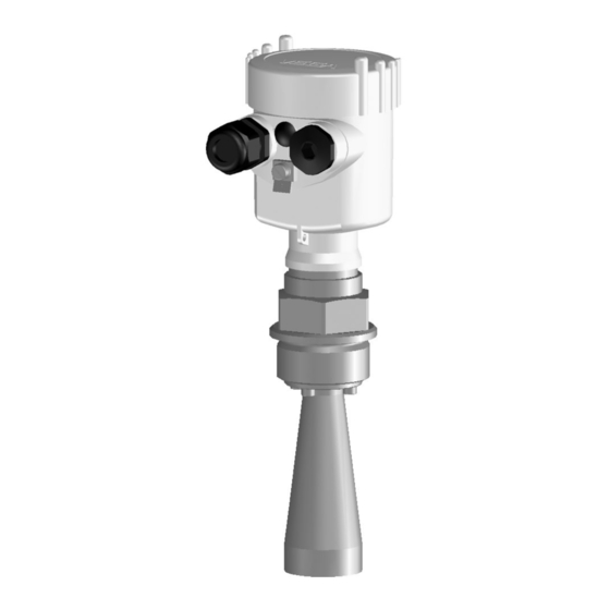
Product description Fig. 1: VEGAPULS 62, threaded version with plastic housing Housing cover with integrated PLICSCOM (optional) Housing with electronics Process fitting with horn antenna 3.2 Principle of operation VEGAPULS 62 is a radar sensor in K-band technology Area of application (emitting frequency approx. -
Page 12: Adjustment
The power supply range can differ depending on the instrument version. The exact range is stated in the Technical data in the Supplement. 3.3 Adjustment VEGAPULS 62 can be adjusted with three different adjustment media: the indicating and adjustment module PLICSCOM an adjustment software acc. to FDT/DTM standard, e.g. - Page 13 Product description Storage and transport temperature see Supplement, Storage and transport temperature Technical data, Ambient conditions Relative humidity 20 ... 85 % VEGAPULS 62 - 4 ... 20 mA/HART...
-
Page 14: Mounting
Use the recommended cable (see chapter "Connecting Moisture to power supply") and tighten the cable entry. You can give your VEGAPULS 62 additional protection against moisture penetration by leading the connection cable downward in front of the cable entry. Rain and condensation water can thus drain off. -
Page 15: Mounting Preparations, Horn Antenna
4.2 Mounting preparations, horn antenna Information: This information applies only to special versions! VEGAPULS 62 is available in versions where the antenna has a bigger diameter than the process fitting (thread/flange). Therefore the antenna must be dis- mounted on the process fitting before mounting. -
Page 16: Mounting Preparations, Parabolic Antenna
fitting (thread/flange). Before starting to mount, the antenna must be dismounted on the flange. Proceed as follows: 1 Clamp VEGAPULS 62 with the flange, e.g. in a bench vice 2 Hold the connection piece (3) with a wrench SW 22 on the flattenings... -
Page 17: Mounting Information
Parabolic antenna 4.4 Mounting information The illustrations on the mounting instructions show a Horn and parabolic anten- VEGAPULS 62 with horn antenna. The mounting instructions also apply to VEGAPULS 62 with parabolic antenna. VEGAPULS 62 - 4 ... 20 mA/HART... - Page 18 Mounting When mounting VEGAPULS 62, keep a distance of at Installation location least 200 mm (7.9 in) to the vessel wall. If the sensor is installed in the center of concave or arched vessel tops, multiple echoes can arise. These can, however, be faded out by an appropriate adjustment (see Setup).
- Page 19 Make sure that you detect the product surface and not the inflowing product. Fig. 8: Inflowing liquid Preferably socket pieces should be dimensioned such Socket that the antenna end protrudes at least 10 mm (0.4 in) out of the socket. VEGAPULS 62 - 4 ... 20 mA/HART...
- Page 20 Fig. 9: Recommended socket mounting If the reflective properties of the medium are good, you can mount VEGAPULS 62 on socket pieces higher than the antenna length. You will find recommended values of the socket heights in the following illustration. The socket end should be smooth and burr-free, if possible also rounded.
- Page 21 In case of agitators in the vessel, a false echo storage Agitators should be carried out with the agitators to be in motion. This ensures that the false reflections of the agitators are saved in different positions. VEGAPULS 62 - 4 ... 20 mA/HART...
- Page 22 (from DK value 1.6) is possible. Surge or bypass tubes must extend all the way down to the requested min. level, as measurement is only possible within the tube. VEGAPULS 62 - 4 ... 20 mA/HART...
- Page 23 If possible, the antenna diameter of the sensor should correspond to the inner diameter of the tube. With VEGAPULS 62 these are approx. 40 mm (1.6 in). The sensor can be used from tube diameters of 40 ... 80 mm (1.6 ...
- Page 24 Fig. 15: VEGAPULS in a bypass tube Marking of the polarisation direction When mounting the sensor on a bypass tube, VEGA- PULS 62 should be mounted at a distance of approx. 300 mm (12 in) or more from the upper pipe connection.
-
Page 25: Preparing The Connection
Provide a reliable separation between the supply circuit and the mains circuits acc. to DIN VDE 0106 part 101. The VEGA power supply units VEGATRENN 149AEx, VEGASTAB 690, VEGADIS 371 as well as all VEGA- METs meet this requirement. Bear in mind the following factors regarding supply... -
Page 26: Connection Procedure
(see following illustration) 7 Insert the wire ends into the open terminals according to the wiring plan 8 Press down the opening levers of the terminals, you will hear the terminal spring closing VEGAPULS 62 - 4 ... 20 mA/HART... -
Page 27: Wiring Plans, Single Chamber Housing
The electrical connection is finished. Fig. 16: Connection steps 6 and 7 4.7 Wiring plans, single chamber housing The following illustrations apply to the non-Ex as well as to the Ex ia version. VEGAPULS 62 - 4 ... 20 mA/HART... - Page 28 Plug connector for VEGACONNECT (I²C interface) Spring-loaded terminals for connection of the ext. indication VEGADIS 61 Ground terminal for connection of the cable screen Spring-loaded terminals for power supply and cable screen VEGAPULS 62 - 4 ... 20 mA/HART...
-
Page 29: Wiring Plans, Double Chamber Housing
Housing overview Fig. 20: Double chamber housing Housing cover, connection compartment Blind stopper or plug M12x1 for VEGADIS 61 (option) Housing cover, electronics compartment Filter element for pressure compensation Cable entry or plug VEGAPULS 62 - 4 ... 20 mA/HART... - Page 30 Terminals for VEGADIS 61 Connection compartment Com. Fig. 22: Connection compartment, double chamber housing Plug connector for VEGACONNECT (I²C interface) Ground terminal for connection of the cable screen Spring-loaded terminals for power supply and cable screen VEGAPULS 62 - 4 ... 20 mA/HART...
-
Page 31: Wiring Plans, Double Chamber Housing Exd
Housing overview Fig. 24: Double chamber housing Housing cover, connection compartment Blind stopper or plug M12x1 for VEGADIS 61 (option) Housing cover, electronics compartment Filter element for pressure compensation Cable entry or plug VEGAPULS 62 - 4 ... 20 mA/HART... - Page 32 Internal connection cable to the connection compartment Terminals for VEGADIS 61 Connection compartment Fig. 26: Connection compartment, double chamber housing Exd Spring-loaded terminals for power supply and cable screen Ground terminal for connection of the cable screen VEGAPULS 62 - 4 ... 20 mA/HART...
- Page 33 Mounting Wiring plan Fig. 27: Wiring plan, double chamber housing Exd Power supply/Signal output VEGAPULS 62 - 4 ... 20 mA/HART...
-
Page 34: Setup With The Indicating And Adjustment Module Plicscom
3 Press PLICSCOM lightly onto the electronics and turn it to the right until it snaps in. 4 Screw housing cover with inspection window tightly back on Removal is carried out in reverse order. VEGAPULS 62 - 4 ... 20 mA/HART... - Page 35 Fig. 28: Installation of PLICSCOM Note: If you intend to retrofit VEGAPULS 62 with PLICSCOM for continuous measured value indication, a higher cover with an inspection glass is required. VEGAPULS 62 - 4 ... 20 mA/HART...
-
Page 36: Adjustment System
The functions of the individual keys are shown in the above illustration. Approx. 10 minutes after the last pressing of a key, an automatic reset to measured value indication is trigger- VEGAPULS 62 - 4 ... 20 mA/HART... -
Page 37: Setup Procedure
Any values not confirmed with [OK] will not be saved. 5.4 Setup procedure After VEGAPULS 62 is connected to power supply or Switch on phase after voltage recurrence, the instrument carries out a self-test for approx. 30 seconds. The following steps are... - Page 38 [OK]. The cursor jumps now to the distance value. 4 Enter the appropriate distance value in m (corre- sponding to the percentage value) for the empty vessel (e.g. distance from the sensor to the vessel bottom). VEGAPULS 62 - 4 ... 20 mA/HART...
- Page 39 Therefore additional option such as Solvent, Chem. mixture and Water based are offered below the menu item Liquid. For solids you choose also Powder/Dust, Granular/ Pellets or Ballast/Pebbels. VEGAPULS 62 - 4 ... 20 mA/HART...
- Page 40 In general, a time of a few seconds is sufficient to smooth the measured value display. Damping Enter the requested parameter via the respective keys, save your settings and jump to the next menu item with the [–>] key. VEGAPULS 62 - 4 ... 20 mA/HART...
- Page 41 A false echo storage detects and marks these false echoes so that they are no longer taken into VEGAPULS 62 - 4 ... 20 mA/HART...
-
Page 42: Menu Schematic
You will find a detailed description of these menu items in the operating instructions manual of the indicating and adjustment module PLICSCOM. VEGAPULS 62 - 4 ... 20 mA/HART... - Page 43 100 % = 100 m³ Diagnostics Basic adjustment Display > Diagnostics Service Info Peak values Meas. reliability Choose curve echo curve Distance-min: 0.234m(d) Sensor status echo curve Presentation of Distance-max: 5.385m(d) echo curve VEGAPULS 62 - 4 ... 20 mA/HART...
- Page 44 Display Diagnostics Service > Info Sensor type Date of manufacture Date of last change Sensor details VEGAPULS 6x 29. April 2003 using PC Software version Serial number 2.00.00 15. May 2003 display 12345678 VEGAPULS 62 - 4 ... 20 mA/HART...
-
Page 45: Setup With Pactware
Fig. 30: Connecting the PC directly to the sensor RS232 connection VEGAPULS 62 I²C adapter cable for VEGACONNECT 3 Necessary components: VEGAPULS 62 PC with PACTware™ and suitable VEGA-DTM VEGACONNECT 3 with I²C adapter cable (article no. 2.27323) power supply unit VEGAPULS 62 - 4 ... 20 mA/HART... -
Page 46: Parameter Adjustment With Pactware
4 ... 20 mA cable. 6.2 Parameter adjustment with PACTware™ Further setup steps are described in the operating instructions manual DTM Collection/PACTware atta- ched to each CD and which can also be downloaded VEGAPULS 62 - 4 ... 20 mA/HART... - Page 47 A detailed description is available in the online help of PACTware™ and the VEGA-DTMs. Note: Keep in mind that for setup of VEGAPULS 62, DTM- Collection 06/2003 or a newer version should be applied. All currently available VEGA-DTMs are provided in the DTM Collection on CD and can be bought from the responsible VEGA agency for a token fee.
-
Page 48: Maintenance And Fault Rectification
Should these measures not be successful, please call in 24 hour service hotline urgent cases the VEGA service hotline under the phone number +49 1805 858550. The hotline is available to you 7 days a week round-the- clock. - Page 49 find an echo, e.g. through incorrect installation or wrong parameter adjust- ment E017 l adjustment span too small à Carry out a fresh adjustment and increase the distance between min. and max. adjustment VEGAPULS 62 - 4 ... 20 mA/HART...
-
Page 50: Exchanging The Oscillator
PS-E.60KHA (approvals CA, DA, EA acc. to VEGA product list) PS-E.60KHC (approvals XM, CX, CM, CK, CI, DX, DM, DK, DI; EX, GX, UX, UF acc. to VEGA product list) In Ex applications, only an oscillator with appropriate Ex approval must be used. - Page 51 Maintenance and fault rectification In both cases, the serial number of VEGAPULS 62 is necessary. The serial numbers are stated on the type label of VEGAPULS 62 or on the delivery note. Proceed as follows: Exchange 1 Switch off power supply...
-
Page 52: Instrument Repair
Use the copy function of the adjustment module PLICSCOM or the adjustment software PACTware™. 7.4 Instrument repair If it is necessary to repair VEGAPULS 62 please proceed as follows: You can download a return form (23 KB) from our Internet homepage www.vega.com under "Services >... - Page 53 Clean the instrument and pack it damage-proof Attach the completed form and possibly also a safety data sheet to the instrument Send the instrument to the respective address of your agency. In Germany to the VEGA headquarters in Schiltach. VEGAPULS 62 - 4 ... 20 mA/HART...
-
Page 54: Dismounting
8.2 Disposal VEGAPULS 62 consists of materials which can be recycled by specialised recycling companies. We have purposely designed the electronic modules to be easily separable. Mark the instrument as scrap and dispose of it according to government regulations (electronic scrap ordinance, ...) -
Page 55: Supplement
2.8 ... 3.6 kg (6.2 ... 13.7 lbs), depending on the thread size and housing - process fitting, flange 5.0 ... 16.2 kg (11 ... 35.7 lbs), depending on the flange size and housing VEGAPULS 62 - 4 ... 20 mA/HART... - Page 56 Reference conditions acc. to DIN EN 61298-1 - temperature 18 ... 30°C (64 ... 86°F) - relative humidity 45 ... 75 % - pressure 860 ... 1060 mbar (86 ... 106 kPa or 12.5 ... 15.4 psi) VEGAPULS 62 - 4 ... 20 mA/HART...
- Page 57 Relating to the nominal range, incl. hysteresis and repeatability, determined acc. to the limit point method. Time to output the correct level (with max. 10 % deviation) after a sudden level change. EIRP: Equivalent isotropically radiated power. VEGAPULS 62 - 4 ... 20 mA/HART...
- Page 58 - Seal Viton - for tube diameter 6 mm - opening pressure 0.5 bar (7.3 psi) - nominal pressure stage PN 250 Tested acc. to the regulations of German Lloyd, GL directive 2 VEGAPULS 62 - 4 ... 20 mA/HART...
- Page 59 LC display in dot matrix Adjustment elements 4 keys Protection - unassembled IP 20 - mounted into the sensor without IP 40 cover depending on the version M12x1, acc. to DIN 43650, Harting, Amphenol-Tuchel, 7/8" FF VEGAPULS 62 - 4 ... 20 mA/HART...
-
Page 60: Power Supply
Ω 1000 Fig. 34: Voltage diagram HART load Voltage limit EEx ia instrument Voltage limit non-Ex instrument/Exd instrument Supply voltage Electrical protective measures Protection IP 66/IP 67 Overvoltage category Protection class VEGAPULS 62 - 4 ... 20 mA/HART... - Page 61 FM CI.I, Div2 (NI)+CI.II, III, Div1 (DIP); FM CI.I-III, Div 1 (IS) Ship approvals GL, LRS, ABS, CCS, RINA Others Deviating data with Ex applications: see separate safety instru- ctions depending on order specification VEGAPULS 62 - 4 ... 20 mA/HART...
-
Page 62: Dimensions
½ NPT M20x1,5/ ½ NPT Fig. 35: Housing versions (with integrated PLICSCOM the height of the housing increases by 9 mm/0.35 in) Plastic housing Stainless steel housing Aluminium double chamber housing Aluminium housing VEGAPULS 62 - 4 ... 20 mA/HART... - Page 63 4" ø95 inch " ø1 " 1½" " ø1 " 2" " ø2 " 3" " ø3 " 4" Fig. 36: VEGAPULS 62 with horn antenna in threaded version Standard with temperature adapter VEGAPULS 62 - 4 ... 20 mA/HART...
- Page 64 " ø1 " " ø2 " 3" 4" " ø3 " Fig. 37: VEGAPULS 62 with horn antenna in threaded version with purging air connection and reflux valve (option) Standard with temperature adapter VEGAPULS 62 - 4 ... 20 mA/HART...
- Page 65 2" " ø2 " 3" " ø3 " 4" Fig. 38: VEGAPULS 62 with horn antenna in threaded version with purging air connection, antenna extension and reflux valve (option) Standard with temperature adapter VEGAPULS 62 - 4 ... 20 mA/HART...
- Page 66 " " 6" 150 lb 279,4 25,4 241,3 8xø22,4 6" 150 lb 11" 1" " 8xø " " " Fig. 39: VEGAPULS 62 with horn antenna in flange version Standard with temperature adapter VEGAPULS 62 - 4 ... 20 mA/HART...
- Page 67 Supplement VEGAPULS 62 with parabolic antenna in threaded version 46mm ") G1½A / 1½ NPT ø 243mm (9 ") Fig. 40: VEGAPULS 62 with parabolic antenna in threaded version Standard with temperature adapter VEGAPULS 62 - 4 ... 20 mA/HART...
- Page 68 " " 8xø " 11" 1" " 8xø " 6" 150 lb 279,4 25,4 241,3 8xø22,4 6" 150 lb Fig. 41: VEGAPULS 62 with parabolic antenna in flange version Standard with temperature adapter VEGAPULS 62 - 4 ... 20 mA/HART...
-
Page 69: Certificates
Supplement 9.3 Certificates CE declaration of conformity Fig. 42: CE declaration of conformity VEGAPULS 62 - 4 ... 20 mA/HART... - Page 70 The surface temperature must not exceed the ignition temperature of the concerned explosive atmosphere. *Single component in the instrument This instrument was judged by a person meeting the requirements acc. to DIN/EN 60079-14. VEGA Grieshaber KG Schiltach, den 25.03.04 i.V. Fruhauf Fig. 43: Manufacturer declaration VEGAPULS 62 - 4 ... 20 mA/HART...
- Page 71 VEGAPULS 62 - 4 ... 20 mA/HART...
- Page 72 VEGAPULS 62 - 4 ... 20 mA/HART...
- Page 73 VEGA Grieshaber KG Am Hohenstein 113 77761 Schiltach Germany Phone +49 7836 50-0 Fax +49 7836 50-201 E-mail: info@de.vega.com www.vega.com ISO 9001 All statements concerning scope of delivery, application, practical use and operating conditions of the sensors and processing systems correspond to the information avail- able at the time of printing.
Need help?
Do you have a question about the VEGAPULS 62 and is the answer not in the manual?
Questions and answers