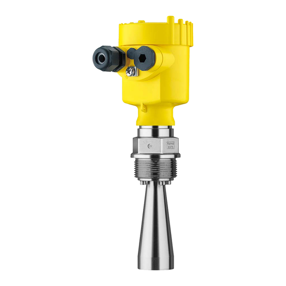
Vega VEGAPULS 62 Operating Instructions Manual
Radar sensor for continuous level measurement of liquids
Hide thumbs
Also See for VEGAPULS 62:
- Operating instructions manual (88 pages) ,
- Quick setup manual (24 pages) ,
- Safety instruction (16 pages)

Related Manuals for Vega VEGAPULS 62


Summary of Contents for Vega VEGAPULS 62
- Page 1 Operating Instructions Radar sensor for continuous level measurement of liquids VEGAPULS 62 Profibus PA Document ID: 36505...
-
Page 2: Table Of Contents
Adjustment system ......................41 Measured value indication - Selection of national language ........... 42 Parameter adjustment ....................43 Saving the parameterisation data ................... 62 Setup with PACTware ......................63 Connect the PC ......................63 Parameter adjustment ....................63 VEGAPULS 62 • Profibus PA... - Page 3 Safety instructions for Ex areas Take note of the Ex specific safety instructions for Ex applications. These instructions are attached as documents to each instrument with Ex approval and are part of the operating instructions. Editing status: 2018-11-23 VEGAPULS 62 • Profibus PA...
-
Page 4: About This Document
Symbols used Document ID This symbol on the front page of this instruction refers to the Docu- ment ID. By entering the Document ID on www.vega.com you will reach the document download. Information, tip, note This symbol indicates helpful additional information. -
Page 5: For Your Safety
During work on and with the device, the required personal protective equipment must always be worn. Appropriate use VEGAPULS 62 is a sensor for continuous level measurement. You can find detailed information about the area of application in chapter "Product description". -
Page 6: Eu Conformity
For operation inside of closed vessels, points a to f in annex E of EN 302372 must be fulfilled. Radio license for USA This approval is only valid for USA. Hence the following text is only available in the English language. VEGAPULS 62 • Profibus PA... -
Page 7: Radio License For Canada
Furthermore, the use of any mechanism that does not allow the main beam of the transmit- ter to be mounted vertically downward is prohibited. VEGAPULS 62 • Profibus PA... - Page 8 Environnement ouvert : Pour l'utilisation hors des cuves fermées, la condition suivante doit être remplie : L'appareil doit être installé et entretenu de manière à garantir une orientation verticale vers le bas du faisceau principal de l’antenne émettrice. De plus, VEGAPULS 62 • Profibus PA...
-
Page 9: Installation And Operation In The Usa And Canada
Canadian Electrical Code. 2.11 Environmental instructions Protection of the environment is one of our most important duties. That is why we have introduced an environment management system with the goal of continuously improving company environmental pro- VEGAPULS 62 • Profibus PA... - Page 10 The environment management system is certified according to DIN EN ISO 14001. Please help us fulfil this obligation by observing the environmental instructions in this manual: • Chapter "Packaging, transport and storage" • Chapter "Disposal" VEGAPULS 62 • Profibus PA...
-
Page 11: Product Description
Go to "www.vega.com", "Search". Enter the serial number. Alternatively, you can access the data via your smartphone: • Download the VEGA Tools app from the "Apple App Store" or the "Google Play Store" • Scan the Data Matrix code on the type label of the instrument or •... -
Page 12: Principle Of Operation
Principle of operation Application area The VEGAPULS 62 radar sensor can be used in a wide variety of ap- plications for continuous level measurement of liquids. It is suitable for applications in storage vessels, reactors and process vessels, even under extremely difficult process conditions. -
Page 13: Packaging, Transport And Storage
• Smartphone/tablet (iOS or Android operating system) • PC/notebook with Bluetooth USB adapter (Windows operating system) You can find further information in the operating instructions "Display and adjustment module PLICSCOM" (Document-ID 36433). VEGAPULS 62 • Profibus PA... - Page 14 PACTware with VEGA-DTM is required. You can find further information in the operating instructions "Interface adapter VEGACONNECT" (Document-ID 32628). The VEGADIS 81 is an external display and adjustment unit for VEGA VEGADIS 81 plics sensors.
- Page 15 3 Product description You find further information in the operating instructions "Antenna impedance cone VEGAPULS 62 and 68" (Document-ID 31381). VEGAPULS 62 • Profibus PA...
-
Page 16: Mounting
You can find detailed information on the process conditions in chapter "Technical data" as well as on the type label. Suitability for the ambient The instrument is suitable for standard and extended ambient condi- conditions tions acc. to IEC/EN 61010-1. VEGAPULS 62 • Profibus PA... -
Page 17: Mounting Preparations
The untwist guards inserted on site must hence be used again. Depending on temperature range and antenna material, these are spring rings according to DIN 217 or wedge lock washers according to DIN 25 201. VEGAPULS 62 • Profibus PA... -
Page 18: Mounting Instructions
4 Mounting Proceed as follows: Parabolic antenna 1. Clamp VEGAPULS 62 with the flange, e.g. in a bench vice 2. Hold the connection piece (1) with a wrench on the flat surfaces (width across flats 22 mm) 3. Loosen counter nut (3) completely with a wrench (width across flats 36 mm) in the direction of the antenna 4. - Page 19 Fig. 5: Mounting of the radar sensor on round vessel tops In vessels with conical bottom it can be advantageous to mount the sensor in the centre of the vessel, as measurement is then possible down to the bottom. VEGAPULS 62 • Profibus PA...
- Page 20 Fig. 7: Mounting of the radar sensor with inflowing medium Mounting socket The socket piece should be dimensioned in such a way that the antenna end protrudes slightly out of the socket. Fig. 8: Recommended socket mounting with horn antenna VEGAPULS 62 • Profibus PA...
- Page 21 Fig. 10: Distance between antenna and socket with horn antenna Fig. 11: Distance between antenna and socket with parabolic antenna If the medium has good reflective properties, VEGAPULS 62 with horn antenna can also be mounted on a longer socket piece. Rec- ommended values for socket heights are specified in the following illustration.
- Page 22 Fig. 13: Alignment in liquids Swivelling holder Proceed as follows to align the sensor with the swivelling holder: 1. Loosen terminal screw of the swivelling holder with a fork spanner SW 13 VEGAPULS 62 • Profibus PA...
- Page 23 4 Mounting Fig. 14: VEGAPULS 62 with swivelling holder Terminal screw Information: The hexagon screws must not be loosened. 2. Align the sensor, check angle of inclination. Max. angle of inclina- tion of the swivelling holder see chapter "Dimensions" 3. Re-tighten the terminal screw, max. torque see chapter "Technical data".
- Page 24 Ths distance piece is used for thermal decoupling of the electron- ics against high process temperatures. Information: The spacer may only be incorporated up to a maximum of 50 mm into the vessel insulation. Only then is a reliable temperature decoupling guaranteed. VEGAPULS 62 • Profibus PA...
-
Page 25: Measurement Setup - Pipes
(ε value ≤ 1.6) is possible. Note the following illustrations and instructions for measurement in a surge pipe. Information: Measurement in a surge pipe is not recommended for extremely adhesive products. VEGAPULS 62 • Profibus PA... - Page 26 4 Mounting Configuration surge pipe 100% Fig. 18: Configuration surge pipe VEGAPULS 62 Radar sensor Polarisation marking Thread or flange on the instrument Vent hole Holes Welding connection through U-profile Ball valve with complete opening Surge pipe end Reflector sheet 10 Fastening of the surge pipe...
- Page 27 Preferably pultruded or straight beaded stainless steel tube • Welded joint should be straight and lie in one axis with the holes • Flanges are welded to the tube according to the orientation of the polarisation VEGAPULS 62 • Profibus PA...
- Page 28 An extension via welding neck flanges or pipe collars is not recom- mended. Measurement in the An alternative to measurement in a surge pipe is measurement in a bypass tube bypass tube outside of the vessel. VEGAPULS 62 • Profibus PA...
- Page 29 • A false signal suppression with the installed sensor is recom- mended but not mandatory • The measurement through a ball valve with unrestricted channel is possible VEGAPULS 62 • Profibus PA...
-
Page 30: Measurement Setup - Flow
Installation in the centre of the flume and vertical to the liquid surface • Distance to the overfall orifice • Distance of orifice opening above ground • Min. distance of the orifice opening to tailwater • Min. distance of the sensor to max. storage level VEGAPULS 62 • Profibus PA... - Page 31 Installation of the sensor at the inlet side • Installation in the centre of the flume and vertical to the liquid surface • Distance to the Venturi flume • Min. distance of the sensor to max. storage level VEGAPULS 62 • Profibus PA...
-
Page 32: Connecting To The Bus System
Prior to setup you have to replace these protective caps with ap- proved cable glands or close the openings with suitable blind plugs. On plastic housings, the NPT cable gland or the Conduit steel tube must be screwed into the threaded insert without grease. VEGAPULS 62 • Profibus PA... -
Page 33: Connecting
5. Insert the cable into the sensor through the cable entry Fig. 23: Connection steps 5 and 6 Single chamber housing Double chamber housing 6. Insert the wire ends into the terminals according to the wiring plan VEGAPULS 62 • Profibus PA... -
Page 34: Wiring Plan, Single Chamber Housing
Selection switch for instrument address For external display and adjustment unit Ground terminal for connection of the cable screening Wiring plan, double chamber housing The following illustrations apply to the non-Ex as well as to the Ex-ia version. VEGAPULS 62 • Profibus PA... - Page 35 For external display and adjustment unit Ground terminal for connection of the cable screening Information: Parallel use of an external display and adjustment unit and a display and adjustment module in the connection compartment is not sup- ported. VEGAPULS 62 • Profibus PA...
-
Page 36: Wiring Plan, Ex-D-Ia Double Chamber Housing
Fig. 29: Top view of the plug connector Pin 1 Pin 2 Pin 3 Pin 4 Contact pin Colour, connection ca- Terminal, electronics ble in the sensor module Pin 1 Brown VEGAPULS 62 • Profibus PA... -
Page 37: Double Chamber Housing With Vegadis-Adapter
Fig. 31: View to the plug connector M12 x 1 Pin 1 Pin 2 Pin 3 Pin 4 Contact pin Colour, connection ca- Terminal, electronics ble in the sensor module Pin 1 Brown Pin 2 White Pin 3 Blue Pin 4 Black VEGAPULS 62 • Profibus PA... -
Page 38: Wiring Plan - Version Ip 66/Ip 68, 1 Bar
6 7 8 Fig. 33: Address selection switch Addresses <100 (selection 0), addresses >100 (selection 1) Decade of the address (selection 0 to 9) Unit position of the address (selection 0 to 9) VEGAPULS 62 • Profibus PA... -
Page 39: Switch-On Phase
The addressing procedure is described in the operating instructions manual "Display and adjustment module. Switch-on phase After VEGAPULS 62 is connected to the bus system, the instrument carries out a self-test for approx. 30 seconds. The following steps are carried out: •... -
Page 40: Set Up With The Display And Adjustment Module
The display and adjustment module is powered by the sensor, an ad- ditional connection is not necessary. Fig. 34: Installing the display and adjustment module in the electronics compart- ment of the single chamber housing VEGAPULS 62 • Profibus PA... -
Page 41: Adjustment System
Adjustment keys • Key functions [OK] key: – Move to the menu overview – Confirm selected menu – Edit parameter – Save value • [->] key: – Change measured value presentation – Select list entry VEGAPULS 62 • Profibus PA... -
Page 42: Measured Value Indication - Selection Of National Language
Any values not confirmed with [OK] will not be saved. Measured value indication - Selection of national language Measured value indica- With the [->] key you move between three different indication modes. tion VEGAPULS 62 • Profibus PA... -
Page 43: Parameter Adjustment
In the main menu item "Setup", the individual submenu items should be selected one after the other and provided with the correct parameters to ensure optimum adjustment of the measurement. The procedure is described in the following. VEGAPULS 62 • Profibus PA... - Page 44 With this menu item, the sensor can be adapted to the applications. The adjustment possibilities depend on the selection "Liquid" or "Bulk solid" under "Medium". The following options are available when "Liquid" is selected: VEGAPULS 62 • Profibus PA...
- Page 45 – Overfilling possible • Properties, sensor: – Low sensitivity to sporadic false echoes – Stable and reliable measured values through averaging – High measurement accuracy, because not set for max. speed – False signal suppression recommended VEGAPULS 62 • Profibus PA...
- Page 46 – False signal suppression recommended Standpipe: • Medium speed: very fast filling and emptying • Vessel: – Vent hole – Joins like flanges, weld joints – Shifting of the running time in the tube • Process/measurement conditions: – Condensation VEGAPULS 62 • Profibus PA...
- Page 47 – Measurement through the vessel top • Process/measurement conditions: – Measured value jump with vessel change • Properties, sensor: – Quick adaptation to changing reflection conditions due to ves- sel change – False signal suppression required VEGAPULS 62 • Profibus PA...
- Page 48 – High sensitivity to interference, because virtually no averaging Caution: If liquids with different dielectric constants separate in the vessel, for example through condensation, the radar sensor can detect under certain circumstances only the medium with the higher dielectric VEGAPULS 62 • Profibus PA...
- Page 49 To perform the adjustment, enter the distance with full and empty ves- sel, see the following example: VEGAPULS 62 • Profibus PA...
- Page 50 2. Edit the percentage value with [OK] and set the cursor to the requested position with [->]. 3. Set the requested percentage value with [+] and save with [OK]. The cursor jumps now to the distance value. VEGAPULS 62 • Profibus PA...
- Page 51 – Percent with radar, guided microwave and ultrasonic sensors – Pressure or height with pressure transmitters • SV2 (Secondary Value 2): – Distance with radar, guided microwave and ultrasonic sensors – Percent with pressure transmitters • Height VEGAPULS 62 • Profibus PA...
- Page 52 Depending on the sensor type, the factory setting is 0 s or 1 s. Setup - Lock adjustment In this menu item, the PIN is activated/deactivated permanently. Entering a 4-digit PIN protects the sensor data against unauthorized access and unintentional modifications. If the PIN is activated perma- VEGAPULS 62 • Profibus PA...
- Page 53 SV2 (Secondary Value 2): Distance value before the adjustment • AI FB1 (OUT) • AI FB2 (OUT) • AI FB3 (OUT) • Height Diagnostics - Device In this menu item, the device status is displayed. status VEGAPULS 62 • Profibus PA...
- Page 54 In this menu item you simulate measured values via the signal output. Hence, the signal path can be tested via the segment coupler up to the input card of the control system. How to start the simulation: 1. Push [OK] VEGAPULS 62 • Profibus PA...
- Page 55 With the adjustment software PACTware and a PC, a high resolution echo curve can be displayed and used to recognize signal changes during operation. In addition, the echo curve of setup can be dis- VEGAPULS 62 • Profibus PA...
- Page 56 This should be done with the lowest possible level so that all potential interfering reflections can be detected. Proceed as follows: 1. Select with [->] the menu item "False signal suppression" and confirm with [OK]. VEGAPULS 62 • Profibus PA...
- Page 57 [ESC] and [->] key. Caution: Note the following if instruments with appropriate approval are used as part of an overfill protection system according to WHG: VEGAPULS 62 • Profibus PA...
- Page 58 However, this menu item is only available if adjustment is enabled in the menu "Setup". In delivery status, the PIN is "0000". Additional settings - Date/ In this menu item, the internal clock of the sensor is set. Time VEGAPULS 62 • Profibus PA...
- Page 59 Peak values, measured value: Resets the measured min. and max. distances to the current measured value. Select the requested reset function [->] and confirm with [OK]. The following table shows the default values of VEGAPULS 62: VEGAPULS 62 • Profibus PA...
- Page 60 • All data of the menu "Setup" and "Display" • In the menu "Additional settings" the items "Distance unit, tem- perature unit and linearization" • The values of the user-programmable linearisation curve VEGAPULS 62 • Profibus PA...
- Page 61 In this menu item, the Profibus ident number of the instrument is Number displayed. Instrument features In this menu item, the features of the sensor such as approval, pro- cess fitting, seal, measuring range, electronics, housing and others are displayed. VEGAPULS 62 • Profibus PA...
-
Page 62: Saving The Parameterisation Data
In the display and adjust- If the instrument is equipped with a display and adjustment module, ment module the parameter adjustment data can be saved therein. The procedure is described in menu item "Copy device settings". VEGAPULS 62 • Profibus PA... -
Page 63: Setup With Pactware
Further setup steps are described in the operating instructions manu- al "DTM Collection/PACTware" attached to each DTM Collection and which can also be downloaded from the Internet. Detailed descrip- tions are available in the online help of PACTware and the DTMs. VEGAPULS 62 • Profibus PA... -
Page 64: Saving The Parameterisation Data
The standard version is available as a download under www.vega.com/downloads and "Software". The full version is avail- able on CD from the agency serving you. Saving the parameterisation data We recommend documenting or saving the parameterisation data via PACTware. -
Page 65: Set Up With Other Systems
Set up with other systems DD adjustment programs Device descriptions as Enhanced Device Description (EDD) are available for DD adjustment programs such as, for example, AMS™ and PDM. The files can be downloaded at www.vega.com/downloads under "Software". VEGAPULS 62 • Profibus PA... -
Page 66: Diagnosis, Asset Management And Service
The data are read out via a PC with PACTware/DTM or the control system with EDD. The echo curves are stored with date and time and the corresponding Echo curve memory echo data. The memory is divided into two sections: VEGAPULS 62 • Profibus PA... -
Page 67: Asset Management Function
(for example during simulation). This status message is inactive by default. It can be activated by the user via PACTware/DTM or EDD. Out of specification: The measured value is unreliable because an instrument specification was exceeded (e.g. electronics temperature). VEGAPULS 62 • Profibus PA... - Page 68 Error in the EEPROM bration • • F261 Error during setup Repeat setup Bit 9 • • False signal suppression faulty Repeat reset Error in the config- • Error when carrying out a reset uration VEGAPULS 62 • Profibus PA...
- Page 69 Bit 14 • Send instrument for repair Error in the non- active linearisation table • • M502 Hardware error EEPROM Exchanging the electronics Bit 15 • Send instrument for repair Error in the diag- nostics memory VEGAPULS 62 • Profibus PA...
-
Page 70: Rectify Faults
• Constant level • Filling • Emptying The images in column "Error pattern" show the real level as a broken line and the level displayed by the sensor as a continuous line. VEGAPULS 62 • Profibus PA... - Page 71 Amplitude or position of a false signal has Determine the reason for the changed changed (e.g. condensation, buildup); false signals, carry out false signal sup- false signal suppression no longer pression, e.g. with condensation time matches actual conditions VEGAPULS 62 • Profibus PA...
- Page 72 9. Measured value Varying condensation or contamination on Carry out a false signal suppression or jumps sporadically to the antenna increase false signal suppression with 100 % during filling condensation/contamination in the close range by editing time VEGAPULS 62 • Profibus PA...
- Page 73 24 hour service hotline Should these measures not be successful, please call in urgent cases the VEGA service hotline under the phone no. +49 1805 858550. The hotline is also available outside normal working hours, seven days a week around the clock.
-
Page 74: Exchanging The Electronics Module
Instruments with approvals can be bound to certain software versions. Therefore make sure that the approval is still effective after a software update is carried out. You can find detailed information in the download area at www.vega.com. VEGAPULS 62 • Profibus PA... -
Page 75: How To Proceed If A Repair Is Necessary
You can find an instrument return form as well as detailed informa- tion about the procedure in the download area of our homepage: www.vega.com. By doing this you help us carry out the repair quickly and without having to call back for needed information. -
Page 76: Dismount
Pass the instrument directly on to a specialised recycling company and do not use the municipal collecting points. If you have no way to dispose of the old instrument properly, please contact us concerning return and disposal. VEGAPULS 62 • Profibus PA... -
Page 77: Supplement
2 … 17.2 kg (4.409 … 37.92 lbs) process fitting and antenna) Ʋ Antenna extension 1.6 kg/m (1.157 lbs/ft) Length antenna extension max. 5.85 m (19.19 ft) Glass with Aluminium and stainless steel precision casting housing VEGAPULS 62 • Profibus PA... - Page 78 20 m (65.62 ft) Ʋ Antenna ø 75 mm (2.953 in), ø 95 mm up to 35 m (114.83 ft) (3.74 in), parabolic antenna Electronics with increased sensitivity Max. measuring range 75 m (246.1 ft) VEGAPULS 62 • Profibus PA...
- Page 79 The values depend to a great extent on the application. Binding specifications are thus not possible. Deviation with bulk solids The values depend to a great extent on the application. Binding specifications are thus not possible. Already included in the meas. deviation VEGAPULS 62 • Profibus PA...
- Page 80 180 °C/356 °F 0.17 % 2.1 % 264 °C/507 °F 0.12 % 1.44 % 9.2 % 366 °C/691 °F 0.07 % 1.01 % 5.7 % 13.2 % 76 % Characteristics and performance data Measuring frequency K-band (26 GHz technology) VEGAPULS 62 • Profibus PA...
- Page 81 90 % of the final value (IEC 61298-2). Outside the specified beam angle, the energy level of the radar signal is 50% (-3 dB) less. EIRP: Equivalent Isotropic Radiated Power. Not with steam. Not with steam. VEGAPULS 62 • Profibus PA...
- Page 82 2 bar (29.0 psig) 5.5 m 4.5 m Air volume with parabolic antenna, depending on pressure (recommended area) Pressure Without reflux valve With reflux valve 0.5 bar (7.25 psig) 3.0 m 1.2 m 0.6 bar (8.70 psig) 3.2 m 1.4 m VEGAPULS 62 • Profibus PA...
- Page 83 0.2 … 1.5 mm² (AWG 24 … 16) Electromechanical data - version IP 66/IP 68 (1 bar) Options of the cable entry Ʋ Cable gland with integrated connec- M20 x 1.5 (cable: ø 5 … 9 mm) tion cable VEGAPULS 62 • Profibus PA...
- Page 84 Data transmission Digital (I²C-Bus) Connection cable Four-wire Sensor version Configuration, connection cable Cable length Standard cable Special cable Screened 4 … 20 mA/HART 50 m ● – – Profibus PA, Founda- 25 m – ● ● tion Fieldbus VEGAPULS 62 • Profibus PA...
- Page 85 Potential connections and electrical separating measures in the instrument Electronics Not non-floating Reference voltage 500 V AC Conductive connection Between ground terminal and metallic process fitting Overvoltage protection Highest continuous operating voltage 35 V DC Galvanic separation between electronics and metal housing parts VEGAPULS 62 • Profibus PA...
-
Page 86: Communication Profibus Pa
Instruments with approvals can have different technical specifications depending on the version. For that reason the associated approval documents of these instruments have to be carefully noted. They are part of the delivery or can be downloaded under www.vega.com, "Instrument search (serial number)" as well as in the download area. - Page 87 0x9702 VE010BFA.GSD PA139702.GSD Cyclical data traffic The master class 1 (e.g. PLC) cyclically reads out measured values from the sensor during opera- tion. The below block diagram below shows which data can be accessed by the PLC. VEGAPULS 62 • Profibus PA...
- Page 88 11 Supplement Fig. 58: VEGAPULS 62: Block diagram with AI FB 1 … AI FB 3 OUT values TB Transducer Block FB 1 … FB 3 Function Block Module of the PA sensors For the cyclic data traffic, VEGAPULS 62 provides the following modules: •...
- Page 89 -10 -11 -12 -13 -14 -15 -16 -17 -18 -19 -20 -21 -22 -23 Sign Significant Significant Exponent Significant (Exponent - 127) Value = (-1) (1 + Significant) Fig. 60: Data format of the measured value VEGAPULS 62 • Profibus PA...
- Page 90 Hi-Alarm tive advisory alarm - high limited 0 x 8d good (non-cascade) - ac- Lo-Lo-Alarm tive critical alarm - low limited 0 x 8e good (non-cascade) - ac- Hi-Hi-Alarm tive critical alarm - high limited VEGAPULS 62 • Profibus PA...
-
Page 91: Dimensions
11 Supplement 11.3 Dimensions The following dimensional drawings represent only an extract of all possible versions. Detailed dimensional drawings can be downloaded at www.vega.com/downloads under "Drawings". Plastic housing ~ 69 mm ~ 84 mm (2.72") (3.31") ø 79 mm ø 79 mm (3.11") - Page 92 Fig. 64: Housing versions with protection rating IP 66/IP 68 (0.2 bar) (with integrated display and adjustment mod- ule the housing is 18 mm/0.71 in higher) Stainless steel single chamber (electropolished) Stainless steel single chamber (precision casting) Stainless steel double chamber housing (precision casting) VEGAPULS 62 • Profibus PA...
- Page 93 ø48 3" ø75 4" ø95 inch 3.94" ø1.58" 1½" 4.72" ø1.89" 2" 8.50" ø2.95" 3" 16.93" ø3.74" 4" Fig. 66: VEGAPULS 62, horn antenna in threaded version Standard With temperature adapter up to 250 °C VEGAPULS 62 • Profibus PA...
- Page 94 1½" ø40 1½" 4.72" ø1.89" 2" ø48 2" 8.50" ø2.95" 3" ø75 3" 16.93" ø3.74" 4" ø95 4" Fig. 67: VEGAPULS 62, horn antenna in flange version Standard With temperature adapter up to 250 °C VEGAPULS 62 • Profibus PA...
- Page 95 8.50" ø2.95" 3" ø75 3" 16.93" ø3.74" 4" ø95 4" Fig. 68: VEGAPULS 62, horn antenna in flange version with purging air connection Standard With temperature adapter up to 250 °C Blind plug Reflux valve VEGAPULS 62 • Profibus PA...
- Page 96 3" ø 75 4" ø 95 inch 2" 4.72" ø 1.89" 3" 8.50" ø 2.95" 4" 11.30" ø 3.74" Fig. 69: VEGAPULS 62, horn antenna in flange version with temperature adapter up to 450 °C VEGAPULS 62 • Profibus PA...
- Page 97 ø 95 inch 3.94" ø 1.58" 1½" 2" 4.72" ø 1.89" 8.50" ø 2.95" 3" 4" 16.93" ø 3.74" Fig. 70: VEGAPULS 62, horn antenna and swivelling holder Standard With temperature adapter up to 250 °C VEGAPULS 62 • Profibus PA...
- Page 98 11 Supplement VEGAPULS 62, horn antenna and swivelling holder, threaded fitting SW 70 mm (2.76") G2 / 2NPT Fig. 71: VEGAPULS 62, horn antenna and swivelling holder, threaded fitting Standard With temperature adapter up to 250 °C VEGAPULS 62 • Profibus PA...
- Page 99 11 Supplement VEGAPULS 62, parabolic antenna and swivelling holder Fig. 72: VEGAPULS 62, parabolic antenna and swivelling holder Standard With temperature adapter up to 200 °C VEGAPULS 62 • Profibus PA...
-
Page 100: Industrial Property Rights
Les lignes de produits VEGA sont globalement protégées par des droits de propriété intellec- tuelle. Pour plus d'informations, on pourra se référer au site www.vega.com. VEGA lineas de productos están protegidas por los derechos en el campo de la propiedad indus- trial. Para mayor información revise la pagina web www.vega.com. - Page 101 Instrument address 38 Instrument master file 86 Vessel Instrument units 56 – insulation 24 Instrument version 61 Vessel form 49 Vessel height 49 Vessel installations 23 Language 53 Linearisation curve 57 Lock adjustment 52 Main menu 43 VEGAPULS 62 • Profibus PA...
- Page 102 Notes VEGAPULS 62 • Profibus PA...
- Page 103 Notes VEGAPULS 62 • Profibus PA...
- Page 104 Subject to change without prior notice © VEGA Grieshaber KG, Schiltach/Germany 2018 VEGA Grieshaber KG Phone +49 7836 50-0 Am Hohenstein 113...
Need help?
Do you have a question about the VEGAPULS 62 and is the answer not in the manual?
Questions and answers