Vega VEGAPULS 62 Operating Instructions Manual
Foundation fieldbus
Hide thumbs
Also See for VEGAPULS 62:
- Operating instructions manual (104 pages) ,
- Quick setup manual (24 pages) ,
- Safety instruction (16 pages)
Table of Contents
Advertisement
Quick Links
Advertisement
Chapters
Table of Contents

Subscribe to Our Youtube Channel
Related Manuals for Vega VEGAPULS 62


Summary of Contents for Vega VEGAPULS 62
- Page 1 Operating Instructions VEGAPULS 62 Foundation Fieldbus Document ID: 36506 Radar...
-
Page 2: Table Of Contents
Parameter adjustment with PACTware ... . 47 Saving the parameter adjustment data ... . 48 VEGAPULS 62 • Foundation Fieldbus... - Page 3 11.3 Dimensions ....... 78 Safety instructions for Ex areas Please note the Ex-specific safety information for installation and operation in Ex areas. These safety instructions are part of the operating instructions manual and come with the Ex-approved instruments. VEGAPULS 62 • Foundation Fieldbus...
-
Page 4: About This Document
This symbol indicates special instructions for Ex applications. List The dot set in front indicates a list with no implied sequence. à Action This arrow indicates a single action. Sequence Numbers set in front indicate successive steps in a procedure. VEGAPULS 62 • Foundation Fieldbus... -
Page 5: For Your Safety
During work on and with the device the required personal protective equipment must always be worn. 2.2 Appropriate use VEGAPULS 62 is a sensor for continuous level measurement. You can find detailed information on the application range in chapter "Product description". -
Page 6: Ce Conformity
2.5 CE conformity The device fulfills the legal requirements of the applicable EC guidelines. By attaching the CE mark, VEGA provides a confirmation of successful testing. You can find the CE conformity declaration in the download area of www.vega.com. -
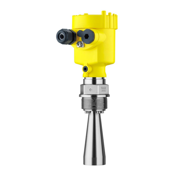
Page 7: Product Description
The serial number on the type label of the instrument allows you to call up the order data, operating instructions manuals, sensor data for the service DTM as well as the test certificate (depending on the instrument). To do this, open under www.vega.com, "VEGA Tools" and "serial number search". Scope of the operating... -
Page 8: Principle Of Operation
The running time of the radar pulses from emission to reception is proportional to the distance and hence to the level. The determined level is converted into an appropriate output signal and outputted as measured value. VEGAPULS 62 • Foundation Fieldbus... -
Page 9: Packaging, Transport And Storage
The interface adapter VEGACONNECT enables the connection of communication-capable instruments to the USB interface of a PC. For parameter adjustment of these instruments, an adjustment software such as PACTware with VEGA-DTM is required. You can find further information in the operating instructions "Interface adapter VEGACONNECT" (Document-ID 32628). - Page 10 Antenna impedance co- The antenna impedance cone is used for optimum transmission of microwaves and for sealing against the process. You find further information in the operating instructions "Antenna impedance cone VEGAPULS 62 and 68" (Document-ID 31381). VEGAPULS 62 • Foundation Fieldbus...
-
Page 11: Mounting
The plastic conemust not be pulled out of the antenna socket. Insert the antenna from below into the vessel socket and secure it against falling off Retighten the antenna with hexagon screws to the antenna socket; torque max. 10 Nm (7.5 lbf ft) VEGAPULS 62 • Foundation Fieldbus... -
Page 12: Mounting Preparations - Parabolic Antenna
fitting before mounting. Proceed as follows: Clamp VEGAPULS 62 with the flange, e.g. in a bench vice Hold the connection piece (3) with a wrench (width across flats 22) on the flattenings Loosen counter nut (2) completely with a wrench (width across flats 36) in the antenna direction... -
Page 13: Mounting Instructions
By turning the instrument in the connection flange or mounting boss, the polarisation can be used to reduce the effects of false echoes. The position of the polarisation plane is marked on the process fitting of the instrument. VEGAPULS 62 • Foundation Fieldbus... - Page 14 Fig. 5: Mounting of the radar sensor on round vessel tops In vessels with conical bottom it can be advantageous to mount the sensor in the center of the vessel, as measurement is then possible down to the lowest point of the vessel bottom. VEGAPULS 62 • Foundation Fieldbus...
- Page 15 Fig. 7: Mounting of the radar sensor with inflowing medium Socket The socket piece should be dimensioned in such a way that the antenna end protrudes at least 10 mm (0.4 in) out of the socket. VEGAPULS 62 • Foundation Fieldbus...
- Page 16 You will find recommended values for socket heights in the following illustration. The socket end should be smooth and burr-free, if possible also rounded. After installation you must carry out a false echo storage. VEGAPULS 62 • Foundation Fieldbus...
- Page 17 If large vessel installations such as struts or supports cause false echoes, these can be attenuated through supplementary measures. Small, inclined sheet metal baffles above the installations scatter the radar signals and prevent direct interfering reflections. VEGAPULS 62 • Foundation Fieldbus...
- Page 18 (C band) should be used. As an alternative, sensors with guided microwave can be used. These are unaffected by foam generation and are best suited for such applications. VEGAPULS 62 • Foundation Fieldbus...
- Page 19 flange holes The marking must show to the direction of the holes in the surge pipe Instructions for the measurement: The 100 % point must be below the upper vent hole and the antenna edge VEGAPULS 62 • Foundation Fieldbus...
- Page 20 Diameter should be constant over the complete length Measurement in the by- An alternative to measurement in a surge pipe is measurement in a pass bypass tube outside of the vessel. VEGAPULS 62 • Foundation Fieldbus...
- Page 21 A false signal suppression with integrated sensor is recommended but not mandatory The measurement through a ball valve with complete run is possible Constructional requirements on the bypass pipe: VEGAPULS 62 • Foundation Fieldbus...
- Page 22 Electronics housing Distance piece Vessel insulation Installation in subsur- For level measurements in concrete silos, the sensors are often face enclosures mounted in protective boxes. These boxes can be for example metallic, closed subsurface enclosures. VEGAPULS 62 • Foundation Fieldbus...
- Page 23 (see chapter "Technical data"); h = max. filling of the rectangular max. flume Overflow orifice (side view) Headwater Tail water Overfall orifice (view from bottom water) In general, the following points must be observed: VEGAPULS 62 • Foundation Fieldbus...
- Page 24 Installation of the sensor at the inlet side Installation in the centre of the flume and vertical to the liquid surface Distance to the Venturi flume Min. distance of the sensor to max. storage level VEGAPULS 62 • Foundation Fieldbus...
-
Page 25: Connecting To The Bus System
(e.g. 1 nF, 1500 V). Low- frequency potential equalisation currents are thus suppressed, but the protective effect against high frequency interference signals remains. VEGAPULS 62 • Foundation Fieldbus... -
Page 26: Connection
When the screwdriver is released, the terminal closes again. Check the hold of the wires in the terminals by lightly pulling on them Connect the screen to the internal ground terminal, connect the outer ground terminal to potential equalisation VEGAPULS 62 • Foundation Fieldbus... -
Page 27: Wiring Plan, Single Chamber Housing
Voltage supply/Signal output Contact pins for the indicating and adjustment module or interface adapter Simulation switch ("1" = mode for simulation release) For external indicating and adjustment unit Ground terminal for connection of the cable screen VEGAPULS 62 • Foundation Fieldbus... -
Page 28: Wiring Plan, Double Chamber Housing
Simulation switch ("on" = mode for simulation release) Connection compart- ment Fig. 23: Connection compartment, double chamber housing Voltage supply/Signal output For indicating and adjustment module or interface adapter Ground terminal for connection of the cable screen VEGAPULS 62 • Foundation Fieldbus... -
Page 29: Wiring Plan With Double Chamber Housing Ex D
Internal connection to the connection compartment Contact pins for the indicating and adjustment module or interface adapter Simulation switch ("1" = mode for simulation release) Internal connection to the plug connector for external indicating and adjustment unit (optional) VEGAPULS 62 • Foundation Fieldbus... - Page 30 Fig. 26: Connection compartment with double chamber housing Ex d Voltage supply/Signal output Ground terminal for connection of the cable screen Plug M12 x 1 for VEGA- DIS 61 Fig. 27: Top view of the plug connector Pin 1...
-
Page 31: Wiring Plan - Version Ip 66/Ip 68, 1 Bar
(+) and blue (-) to power supply or to the processing system Shielding 5.7 Switch on phase After VEGAPULS 62 is connected to the bus system, the instrument carries out a self-test for approx. 30 seconds. The following steps are carried out: Internal check of the electronics Indication of the instrument type, the firmware as well as the... -
Page 32: Insert Indicating And Adjustment Module
Fig. 29: Insert indicating and adjustment module Note: If you intend to retrofit the instrument with an indicating and adjustment module for continuous measured value indication, a higher cover with an inspection glass is required. VEGAPULS 62 • Foundation Fieldbus... -
Page 33: Adjustment System
The functions of the individual keys are shown in the above illustration. Approx. 10 minutes after the last pressing of a key, an automatic reset to measured value indication is triggered. Any values not confirmed with [OK] will not be saved. VEGAPULS 62 • Foundation Fieldbus... -
Page 34: Parameter Adjustment
With bulk solids, these are dust generation, material cone and additional echoes from the vessel wall. To adapt the sensor to these different measuring conditions, the selection "Liquid" or "Bulk solid" should be made in this menu item. VEGAPULS 62 • Foundation Fieldbus... - Page 35 The following options are available when "Liquid" is selected: The selection "Standpipe" opens a new window in which the inner diameter of the applied standpipe is entered. The following features form the basis of the applications: Storage tank: VEGAPULS 62 • Foundation Fieldbus...
- Page 36 Very agitated surface, foam generation Dosing vessel: Setup: all vessel sizes possible Product speed: Fast filling and emptying Vessel is very often filled and emptied Vessel: narrow installation situation Process/measurement conditions Condensation, buildup on the antenna VEGAPULS 62 • Foundation Fieldbus...
- Page 37 In outside facilities water and snow on the vessel top possible Transportable plastic tank: Vessel Material and thickness different Measurement through the vessel top Process/measurement conditions Measured value jump with vessel change Open water (gauge measurement): Gauge rate of change: slow gauge change Process/measurement conditions VEGAPULS 62 • Foundation Fieldbus...
- Page 38 If you want to measure the total height of both liquids reliably, please contact our service department or use an instrument specially designed for interface measurement. The following options are available when "Bulk solid" is selected: The following features form the basis of the applications: VEGAPULS 62 • Foundation Fieldbus...
- Page 39 Large distance to the medium Demonstration: Adjustment for all applications which are not typically level measurement Sensor accepts all measured value changes within the measuring range immediately Typical applications Instrument demonstration Object recognition/monitoring (additional settings required) VEGAPULS 62 • Foundation Fieldbus...
- Page 40 10 % and 90 % is also possible. Starting point for these distance specifications is always the seal surface of the thread or flange. By means of these settings, the real level is calculated. VEGAPULS 62 • Foundation Fieldbus...
- Page 41 Setup/Max. adjustment Proceed as follows: Select with [->] the menu item max. adjustment and confirm with [OK]. Prepare the percentage value for editing with [OK] and set the cursor to the requested position with [->]. VEGAPULS 62 • Foundation Fieldbus...
- Page 42 The selected curve is continuously updated. With the [OK] key, a submenu with zoom functions is opened: "X-Zoom": Zoom function for the meas. distance "Y-Zoom": 1, 2, 5 and 10x signal magnification in "dB" VEGAPULS 62 • Foundation Fieldbus...
- Page 43 Proceed as follows: Select the menu item "Additional settins" with [->] and confirm with [OK]. With [->] you have to select the menu item "False signal suppression" and confirm with [OK]. Confirm again with [OK]. VEGAPULS 62 • Foundation Fieldbus...
- Page 44 [ESC] and [->] key. Additonal settings/Sen- With radar sensors with standpipe antenna, the sensor length is sor length already preset in this menu item. When shortening the standpipe antenna afterwards, this value must be corrected respectively. VEGAPULS 62 • Foundation Fieldbus...
- Page 45 Peak values measured value: Resetting of the measured min. and max. distances to the actual measured value. Select the requested reset function [->] and confirm with [OK]. The following table shows the default values of VEGAPULS 62: Menu section Menu item...
-
Page 46: Saving The Parameter Adjustment Data
If it is necessary to exchange a sensor, then the indicating and adjustment module is inserted into the replacement instrument and the data are also written into the sensor via the menu item "Copy sensor data". VEGAPULS 62 • Foundation Fieldbus... -
Page 47: Setup With Pactware
DTM Collection. Furthermore, not all described functions are included in older firmware versions. You can download the latest instrument software from our homepage. A description of the update procedure is also available in the Internet. VEGAPULS 62 • Foundation Fieldbus... -
Page 48: Saving The Parameter Adjustment Data
The standard version is available as a free-of-charge download under http://www.vega.com. The full version is available on CD from the agency serving you. 7.3 Saving the parameter adjustment data We recommend documenting or saving the parameter adjustment data via PACTware. -
Page 49: Set Up With Other Systems
DD adjustment programs such as, for example, AMS™ and PDM. A free-of-charge download of these files is available via Internet. Move via www.vega.com and "Downloads" to "Software". 8.2 Communicator 375, 475 Device descriptions for the instrument are available as DD or EDD for parameter adjustment with the Field Communicator 375 or 475. -
Page 50: Diagnosis And Service
PACTware/DTM or the control system with EDD. Data are also read out or reset. Depending on the instrument, the echo curve created during setup can be stored alternatively also via the indicating and adjustment module. VEGAPULS 62 • Foundation Fieldbus... -
Page 51: Error Messages According To Ne 107
Clean or exchange process component or antenna F017 l Adjustment not within spe- l Change adjustment accor- cification ding to the limit values Adjustment (difference between min. span too small and max. ≥ 10 mm) VEGAPULS 62 • Foundation Fieldbus... - Page 52 Adjustment not within the l Check or correct installa- vessel height/measuring tion and/or parameter ad- Installation/S- range justment etup error l Max. measuring range of l Use an instrument with the instrument not suffici- bigger measuring range VEGAPULS 62 • Foundation Fieldbus...
- Page 53 filling Overfilling l Check level in the vessel Maintenance The following table shows the error codes and text messages in the status message "Maintenance" and provides information on causes as well as corrective measures. VEGAPULS 62 • Foundation Fieldbus...
-
Page 54: Fault Rectification
Further comprehensive diagnostics can be carried out on a PC with the software PACTware and the suitable DTM. In many cases, the causes can be determined this way and faults rectified. VEGAPULS 62 • Foundation Fieldbus... -
Page 55: Exchanging The Electronics Module
24 hour service hotline Should these measures not be successful, please call in urgent cases the VEGA service hotline under the phone no. +49 1805 858550. The hotline is available to you 7 days a week round-the-clock. Since we offer this service world-wide, the support is only available in the English language. -
Page 56: How To Proceed In Case Of Repair
Connect the sensor to power supply and provide a connection from the PC to the instrument via the interface adapter. Start PACTware and move via the menu "Project" to the VEGA project assistant. Select "USB" and "Set instruments online". Activate the project assistant with "Start". -
Page 57: Dismounting
Correct disposal avoids negative effects to persons and environment and ensures recycling of useful raw materials. Materials: see chapter "Technical data" If you have no way to dispose of the old instrument properly, please contact us concerning return and disposal. VEGAPULS 62 • Foundation Fieldbus... -
Page 58: Supplement
Antenna extension 5.85 m (19.19 ft) Length antenna extension max. Torque for NPT cable glands and Conduit tubes max. 10 Nm (7.376 lbf ft) Plastic housing max. 50 Nm (36.88 lbf ft) Aluminium/Stainless steel housing VEGAPULS 62 • Foundation Fieldbus... - Page 59 Antenna ø 75 mm (2.953 in) up to 40 m (131.23 ft) Antenna ø 95 mm (3.74 in) up to 50 m (164 ft) up to 75 m (246.1 ft) Parabolic antenna Output variable Output VEGAPULS 62 • Foundation Fieldbus...
-
Page 60: Primary_Value
0,5 m (1.6 ft) - 2 mm (- 0.079 in) - 10 mm (- 0.394 in) Fig. 34: Deviation under reference conditions Reference plane Antenna edge Recommended measuring range Reproducibility ≤ ±1 mm Deviation with bulk solids VEGAPULS 62 • Foundation Fieldbus... - Page 61 264 °C/507 °F 0.12 % 1.44 % 9.2 % 366 °C/691 °F 0.07 % 1.01 % 5.7 % 13.2 % 76.0 % Characteristics and performance data Frequency K-band (26 GHz technology) Measuring cycle time 450 ms Standard electronics approx. VEGAPULS 62 • Foundation Fieldbus...
- Page 62 first time 90 % of the final value (IEC 61298-2). Outside the specified beam angle, the energy of the radar signal has a level of -3 dB (50 %). EIRP: Equivalent Isotropic Radiated Power VEGAPULS 62 • Foundation Fieldbus...
- Page 63 Electromechanical data - version IP 66/IP 67 and IP 66/IP 68; 0.2 bar Cable entry/plug Tested according to the guidelines of German Lloyd, GL directive 2. Depending on the version M12 x 1, according to ISO 4400, Harting, 7/8" FF. VEGAPULS 62 • Foundation Fieldbus...
- Page 64 Standard length 1000 m (3280 ft) Max. length 25 mm (0.984 in) with 25 °C (77 °F) Min. bending radius Only with Ex d version Only with Ex d version Only with Ex d version VEGAPULS 62 • Foundation Fieldbus...
- Page 65 14 … 32 V DC EEx-d instrument Power supply by/max. number of sensors max. 32 (max. 10 with Ex) H1 power supply Electrical protective measures Protection, depending on housing version IP 66/IP 67 Plastic housing VEGAPULS 62 • Foundation Fieldbus...
- Page 66 Depending on the version, instruments with approvals can have different technical data. For these instruments, the corresponding approval documents have to be taken into account. These are part of the delivery or can be downloaded under www.vega.com via "VEGA Tools" and "serial number search" as well as via "Downloads" and "Approvals".
-
Page 67: Supplementary Information Foundation Fieldbus
Resource Block (RB) Transducer Block (TB) Standard Block (AI) 30 mS Execution Time Advanced Function Blocks Discret Input (DI) PID Control Output Splitter (OS) Signal Characterizer (SC) Integrator Input Selector (IS) Arithmetic (AR) Diagnostics Standard Advanced VEGAPULS 62 • Foundation Fieldbus... -
Page 68: Primary_Value_Unit
The function block "Analog Input (AI)" takes the original measured value selected by a Channel Number and makes it available to additional function blocks on its output. Fig. 36: Schematic presentation function block Analog Input (AI) VEGAPULS 62 • Foundation Fieldbus... - Page 69 The function block "PID Control " is a key component for various tasks in the process automation and is used universally. PID blocks can be cascaded if this is necessary or requested due to different time constants with the primary and secondary process measurement. Fig. 38: Schematic presentation function block PID Control VEGAPULS 62 • Foundation Fieldbus...
- Page 70 A retrograde calculation function is realised by using the linear imaging function inversely. A cascading of several Output Splitters is supported by an integrated decision table for the combinability of inputs and outputs. Fig. 39: Schematic presentation function block Output Splitter VEGAPULS 62 • Foundation Fieldbus...
- Page 71 Optionally the function axis can be exchanged in channel 2 so that the block can be also used in a reverse control loop. Fig. 40: Schematic presentation function block Signal Characterizer VEGAPULS 62 • Foundation Fieldbus...
- Page 72 flow volume can be calculated and integrated. This can be used for calculation of volume and mass changes in the vessel or for optimisation of flow controls. Fig. 41: Schematic presentation function block Integrator VEGAPULS 62 • Foundation Fieldbus...
- Page 73 The user can select the requested algortihm according to the name without known the formula. The following algorithms are available: Flow compensation, linear Flow compensation, square root Flow compensation, approximate BTU flow Traditional Multiply Divide Average Traditional Summer Fourth order polynomial Simple HTG compensated level VEGAPULS 62 • Foundation Fieldbus...
-
Page 74: Secondary_Value_2
FILL_HEIGHT_VALUE Filling height. The unit is defined in " LUE_UNIT " FILL_HEIGHT_VALUE_UNIT Filling height unit CONST_VALUE Constant value Secondary value 1 type SECONDARY_VALUE_1_- TYPE Secondary value 2 type SECONDARY_VALUE_2_- TYPE FILL_HEIGHT_VALUE_Type Filling height value type VEGAPULS 62 • Foundation Fieldbus... - Page 75 Electronics variant, probe type, max. measuring range, antenna extension length, adjustment propagation antenna extension lprapproval configuration ADJUSTMENT_LIMITS_MIN Min. range min.-/max.- values physical, percent, offset ADJUSTMENT_LIMITS_MAX Max. range min.-/max.- values physical, percent, offset FALSE_SIGNAL_COMMAND FALSE_SIGNAL_CMD_C- REATE_EXTEND FALSE_SIGNAL_CMD_DE- LET_REGION FALSE_SIGNAL_CMD_STA- Busy, last command, errorcode VEGAPULS 62 • Foundation Fieldbus...
- Page 76 Limitation measuring range begin, safety of measuring range SERVICE LEVEL_ECHO_INFO Level echo ID, amplitude, measurement safety DEVICE_STATUS Device status FALSE_SIGNAL_LIMITS False signal distance min./max. USER_PEAK_ELEC_TEMP Min.-/max.- values of electronics temperature, date USER_MIN_MAX_PHYSI- Min.-/max.- distance values, date CAL_VALUE VEGAPULS 62 • Foundation Fieldbus...
- Page 77 Width focusing range, time for opening the focusing range, min. measurement reliability in and outside the focusing range NOISE_DETECTION_INFO Increase of the system noise NOISE_DETECTION_CON- System noise treatment ECHO_MEM_SAVE_CUR- VE_TYPE ECHO_MEM_STATE Busy, curve type, error code VEGAPULS 62 • Foundation Fieldbus...
-
Page 78: Dimensions
11 Supplement 11.3 Dimensions The following dimensional drawings represent only an extract of the possible versions. Detailed dimensional drawings can be downloaded on www.vega.com under "Downloads" and "Drawings". Plastic housing ~ 69 mm ~ 84 mm (3.31") (2.72") ø 79 mm ø... - Page 79 ø 86 mm ø 80 mm ø 79 mm (3.39") (3.15") (3.11") M16x1,5 M20x1,5/ ½ NPT M20x1,5/ M20x1,5/ ½ NPT ½ NPT Single chamber version, electropolished Single chamber version, precision casting Double chamber version, precision casting VEGAPULS 62 • Foundation Fieldbus...
- Page 80 (4.06") ø 84 mm ø 80 mm ø 77 mm (3.31") (3.15") (3.03") M16x1,5 M20x1,5 M20x1,5/ ½ NPT M20x1,5/ ½ NPT Single chamber version, electropolished Single chamber version, precision casting Double chamber version, precision casting VEGAPULS 62 • Foundation Fieldbus...
- Page 81 3" ø75 4" ø95 inch 3.94" ø1.58" 1½" 4.72" ø1.89" 2" 8.50" ø2.95" 3" 16.93" ø3.74" 4" Fig. 49: VEGAPULS 62 - horn antenna in threaded version Standard With temperature adapter up to 250 °C VEGAPULS 62 • Foundation Fieldbus...
- Page 82 ø40 1½" 4.72" ø1.89" 2" ø48 2" 8.50" ø2.95" 3" ø75 3" 16.93" ø3.74" 4" ø95 4" Fig. 50: VEGAPULS 62 - horn antenna in flange version Standard With temperature adapter up to 250 °C VEGAPULS 62 • Foundation Fieldbus...
- Page 83 ø 75 4" ø 95 inch 2" 4.72" ø 1.89" 3" 8.50" ø 2.95" 4" 11.30" ø 3.74" Fig. 51: VEGAPULS 62 - horn antenna in flange version with temperature adapter up to 450 °C VEGAPULS 62 • Foundation Fieldbus...
- Page 84 1½" 3.94" ø 1.58" 4.72" ø 1.89" 2" 3" 8.50" ø 2.95" 16.93" ø 3.74" 4" Fig. 52: VEGAPULS 62 - horn antenna and swivelling holder Standard With temperature adapter up to 250 °C VEGAPULS 62 • Foundation Fieldbus...
- Page 85 11 Supplement - parabolic antenna and swivelling holder VEGAPULS 62 Fig. 53: VEGAPULS 62 - parabolic antenna and swivelling holder Standard With temperature adapter up to 200 °C VEGAPULS 62 • Foundation Fieldbus...
- Page 86 Les lignes de produits VEGA sont globalement protégées par des droits de propriété intellectuelle. Pour plus d'informations, on pourra se référer au site http://www.vega.com VEGA lineas de productos están protegidas por los derechos en el campo de la propiedad industrial. Para mayor información revise la pagina web http://www.vega.com Линии...
- Page 87 11 Supplement VEGAPULS 62 • Foundation Fieldbus...
- Page 88 All statements concerning scope of delivery, application, practical use and operating conditions of the sensors and processing systems correspond to the information avail- able at the time of printing. © VEGA Grieshaber KG, Schiltach/Germany 2011 36506-EN-110127 Subject to change without prior notice...
Need help?
Do you have a question about the VEGAPULS 62 and is the answer not in the manual?
Questions and answers