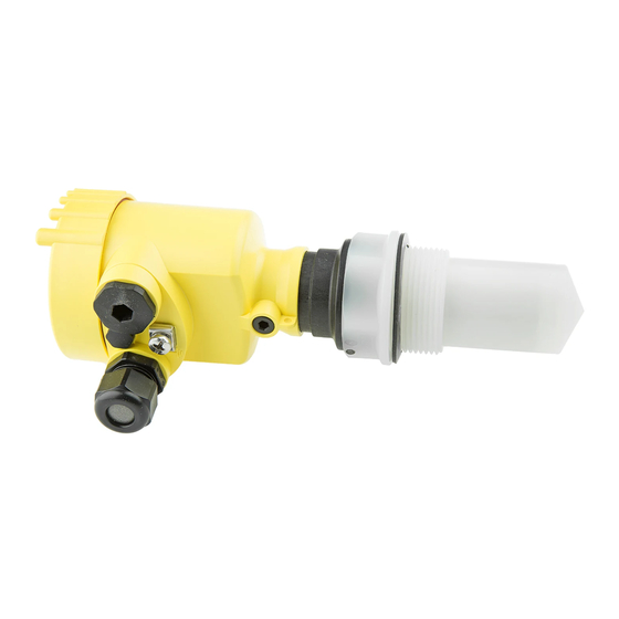
Vega VEGAPULS 61 Safety Manual
Vegapuls series 60
4...20 ma/hart
Hide thumbs
Also See for VEGAPULS 61:
- Operating instructions manual (100 pages) ,
- Quick setup manual (24 pages) ,
- Quick setup manual (24 pages)
Advertisement
Quick Links
Advertisement

Summary of Contents for Vega VEGAPULS 61
- Page 1 Safety Manual VEGAPULS series 60 4 … 20 mA/HART Radar...
-
Page 2: Table Of Contents
Contents Contents 1 Functional safety In general ......Planning ......Instrument parameter adjustment . -
Page 3: Functional Safety
This safety manual applies to measuring systems consisting of Scope the VEGAPULS series 60 radar sensor in two-wire and four- wire versions 4 … 20 mA/HART: VEGAPULS 61, 62, 63, 65, 66, 67, 68 Valid hardware and software versions: Serial number of the Sensor software... - Page 4 Functional safety λ Rate for dangerous detected failure λ Rate for dangerous undetected failure Diagnostic Coverage of safe failures; DC = λ /(λ +λ Diagnostic Coverage of dangerous failures; DC = λ /(λ +λ Failure In Time (1 FIT = 1 failure/10 MTBF Mean Time Between Failure MTTF...
-
Page 5: Planning
Functional safety According to IEC 61511-1, paragraph 11.4.4, the failure Proven in use tolerance HFT can be reduced by one for proven-in-use subsystems if the following conditions are met: The instrument is proven in use Only process-relevant parameters can be modified on the instrument (e.g. - Page 6 Functional safety If the internal diagnosis system detects a failure, the measuring system goes into fault mode. A dangerous undetected failure exists if the measuring system switches neither to the defined safe condition nor to the failure mode when the process requires it. If the measuring system delivers output currents of "fail low"...
-
Page 7: Instrument Parameter Adjustment
Functional safety The following assumptions form the basis for the implemen- Assumptions tation of FMEDA: Failure rates are constant, wear of the mechanical parts is not taken into account Failure rates of external power supplies are not taken into account Multiple errors are not taken into account The average ambient temperature during the operating time is 40 °C (104 °F) - Page 8 Functional safety In the adjustment software, the parameter "Sensor according Create a measurement loop to SIL" must be selected in the menu level "Basic adjustment". If the indicating and adjustment module is used, the parameter "SIL" must be actived in the menu level "Service". The parameter adjustment of the interference current influen- Reaction in case of failure ces the safety-related characteristics.
-
Page 9: Setup
Functional safety 1.4 Setup Take note of the mounting and installation instructions of the Mounting and installation operating instructions manual. In the setup procedure, a check of the safety function by means of an initial filling is recommended. 1.5 Reaction during operation and in case of failure The adjustment elements or device parameters must not be modified during operation. -
Page 10: Safety-Related Characteristics
Functional safety The test must be carried out in a way that verifies the flawless operation of the safety functions in conjunction with all system components. This is ensured by a controlled reaching of the response height during filling. If filling up to the response height is not possible, then a response of the measuring system must be triggered by a suitable simulation of the level or the physical measuring effect. - Page 11 E042/E043 (hardware error) <2 min E036/E037 (no executable sensor software) <15 h VEGAPULS 68 and VEGAPULS 61, 62, 63 with increased sensitivity 2 … 36 min E013 (no measured value available) depending on the application E042/E043 (hardware error) <4 min...
- Page 12 Functional safety <0.358x10 The chronological sequence of PFD is nearly linear to the Time-dependent process of operating time over a period up to 10 years. The above values apply only to the T interval after which a recurring function Proof test must be carried out.
- Page 13 Functional safety VEGAPULS series 60 - 4 … 20 mA/HART...
- Page 14 Functional safety VEGAPULS series 60 - 4 … 20 mA/HART...
- Page 15 Functional safety VEGAPULS series 60 - 4 … 20 mA/HART...
- Page 16 All statements concerning scope of delivery, application, practical use and operating conditions of the sensors and processing systems correspond to the information avail- able at the time of printing. © VEGA Grieshaber KG, Schiltach/Germany 2007 31338-EN-070510 Subject to change without prior notice...


Need help?
Do you have a question about the VEGAPULS 61 and is the answer not in the manual?
Questions and answers