Table of Contents
Advertisement
Advertisement
Table of Contents

Subscribe to Our Youtube Channel
Related Manuals for Kontron KTH81/mITX


Summary of Contents for Kontron KTH81/mITX
- Page 1 KTH81/mITX KTQ87/mITX KTH81/Flex KTQ87/Flex KTD-N0882-I The pulse of innovation...
-
Page 2: Table Of Contents
Power Consumption ........................ 22 mITX, Total System power example ....................... 23 Flex, Total System power example ........................ 26 Connector Locations ................30 KTQ87/mITX (KTH81/mITX) - frontside ..................30 KTQ87/Flex (KTH81/Flex) - frontside ..................31 Connector Definition ................32 IO-Area Connectors ................33 DP Connectors (DP0, DP1, DP2) .................... - Page 3 KTD-N0882-I Page 3 Table of Contents USB 8 & 9 (USB8/9) (USB3) ........................45 Serial COM1 – COM2 Ports (COM1, COM2) ..................46 Audio Connectors ........................47 Headphone and Mic2 ..........................47 Front Speakers (LINEOUT) .......................... 47 SPDIF (SP-DIF) ............................47 7.10 Front Panel Connector (FRONTPNL) (J2) ..................
- Page 4 KTD-N0882-I Page 4 Table of Contents TPM Configuration ............................ 96 10.4 Boot ........................... 97 10.5 Exit ............................. 98 KTQ87/KTH81 Users Guide...
-
Page 5: Document Revision History
KTD-N0882-I Page 5 Document Details Document Revision History Revision Date Comment March 5 2015 I7-4790S, I5-4590S added. EXT_BAT max. 3.47 V. Always On jumper description corrected. July 16 2014 Top text correction. Improved cooler information. Feature connector corrections. BIOS part upgraded. May 27 2014 Display configuration table improved. -
Page 6: Copyright Notice
Brand and product names are trademarks or registered trademarks of their respective owners. Disclaimer KONTRON Technology A/S reserves the right to make changes without notice to any product, including circuits and/or software described or contained in this manual in order to improve design and/or performance. -
Page 7: Life Support Policy
Warranty KONTRON Technology warrants its products to be free from defects in material and workmanship during the warranty period. If a product proves to be defective in material or workmanship during the warranty period KONTRON Technology will, at its sole option, repair or replace the product with a similar product. - Page 8 2. Driver Version numbers (Graphics, Network, and Audio). 3. Attached Hardware: Harddisks, CD-Rom, LCD Panels etc. If the Kontron Technology product seems to be defect and you want to return it for repair, please follow the guide lines from the following page: http://kontron.com/services/rma-information/kontron-technology-a-s/...
-
Page 9: Introduction
Page 9 Introduction Introduction This manual describes the KTH81/mITX, KTQ87/mITX, KTH81/Flex & KTQ87/Flex boards made by KONTRON Technology A/S. The boards will also be denoted KTQ87 & KTH81. The KTQ87/KTH81 boards are based on the Q87/H81 chipsets supporting 4 generation Intel® Haswell i7 -, i5 2Core and 4Core desktop processors, Haswell Dual Core Pentium and Haswell Dual Core Celeron. -
Page 10: Installation Procedure
Installation Procedure Installing the Board To get the board running follow these steps. If the board shipped from KONTRON has already components like RAM and CPU cooler mounted, then relevant steps below can be skipped. 1. Turn off the PSU (Power Supply Unit) Warning: Turn off PSU (Power Supply Unit) completely (no mains power connected to the PSU) or leave the Power Connectors unconnected while configuring the board. -
Page 11: Requirements Iec60950
KTD-N0882-H Page 11 Installation 9. Mounting the board in chassis Warning: When mounting the board to chassis etc. please notice that the board contains components on both sides of the PCB which can easily be damaged if board is handled without reasonable care. -
Page 12: System Specifications
KTD-N0882-I Page 12 System Specification System Specifications Component main data The table below summarizes the features of the KTH81/mITX, KTQ87/mITX, KTH81/Flex and KTQ87/Flex. Form factor mITX (miniITX) 170,18 mm by 170,18 mm Flex (Flex-ATX) 190,5 mm by 228,6 mm Processor Support the following 4 Generation Intel®... - Page 13 1x USB2.0 ports on internal mSATA connector (mITX only) • 2x Serial ports (RS232) on internal pinrows • 1x SATA3.0, 2x SATA2.0 and 1x mSATA (SATA3.0, USB, LPC) (KTH81/mITX) • 5x SATA3.0 and 1x mSATA (SATA3.0, USB, LPC) (KTQ87/mITX) •...
- Page 14 Wake On LAN (WOL) supported I/O Control Via ITE IT8516E Embedded Controller via LPC Bus interface Expansion • 1x PCIe x16 (Gen 2.0), 1x mPCIe (w. USB2.0) (KTH81/mITX) Capabilities • 1x PCIe x16 (Gen 2.0 & 3.0), 1x mPCIe (w. USB2.0) (KTQ87/mITX) •...
- Page 15 -20°C – 70°C; lower limit of storage temperature is defined by specification restriction of on-board CR2032 battery. Board with battery has been verified for storage temperature down to -40°C by Kontron. 5% - 95% relative humidity (non-condensing) Electro Static Discharge (ESD) / Radiated Emissions (EMI): All Peripheral interfaces intended for connection to external equipment are ESD/ EMI protected.
-
Page 16: System Overview
Q87/H81 (Lynx Point) Desktop Platform controller Hub 240 pins DDR3 UDIMM Dual Channel, Intel PC3 10600/12800: LVDS / DP (DisplayPort 1.2): 2 slots, 1-16GB total. 2x DP (KTH81/mitx) Processor 4 slots, 1-32GB total (KTQ87/Flex). 3x DP (KTQ87/mitx) HASWELL DP + DP or LVDS (KTH81/Flex) -
Page 17: Processor Support Table
CPU’s are indicated by text. Some processors in the list are distributed from Kontron, those CPU’s are marked by an * (asterisk). However please notice that this marking is only guide line and maybe not fully updated. - Page 18 Different coolers are available on the market and some is not generating any airflow or is blocking the airflow around these components, causing reduced lifetime. It is recommended to use a cooler like the Kontron PN 1046-6305 “KTQ77 Cooler”.
-
Page 19: System Memory Support
P/N will be maintained so that EOL module will be replaced by other similar type of qualified module. As a minimum it is recommend using Kontron memory modules for prototype system(s) in order to prove stability of the system and as for reference. -
Page 20: Ktq87/Kth81 Graphics Subsystem
KTD-N0882-I Page 20 System Specification KTQ87/KTH81 Graphics Subsystem The KTQ87 / KTH81 equipped with Intel ® i5 or i7 processor supports Intel ® HD Graphics 4600. KTQ87/KTH81 supports three/two DisplayPort directly from processor. The DP interface supports the DisplayPort 1.2 specification. The PCH supports High-bandwidth Digital Content Protection for high definition content playback over digital interfaces. -
Page 21: Display Configurations
KTD-N0882-I Page 21 System Specification Display Configurations: LVDS HDMI, DVI or DP HDMI, DVI or DP HDMI, DVI or DP KTH81/mITX KTQ87/mITX KTH81/Flex KTH81/Flex KTQ87/Flex KTQ87/Flex Note the maximum resolutions: LVDS 1920 x 1200 @ 60 Hz HDMI 2560 x 1600 @ 60 Hz... -
Page 22: Power Consumption
In some cases, this can lead to compatibility problems with ATX power supplies, which require a minimum load to stay in regulation. The KTQ87/mITX / KTH81/mITX board must powered through the ATX4P (4-pole) and the ATX24P (24-pole) connector using standard ATX power supply. -
Page 23: Mitx, Total System Power Example
Standard system configuration equipped with PCIex16 graphics card, mSATA 32GB, 4x SATA disks, Intel 2.5Ghz CPU, 2x DIMM (8GB Modules), DVI Monitor, Keyboard & Mouse, 4x 1-8GB USB Sticks, 12V active cooler, 400W ATX PSU. Note: KTH81/mITX power results are similar to KTQ87/mITX. KTQ87/KTH81 Users Guide... - Page 24 KTD-N0882-I Page 24 System Specification mITX, Low Power Configuration results DOS Idle, Mean, No external load Current draw Power consumption Supply [mA] +12V 1.158 +12V P4 1359 16.390 3.228 +3V3 1.664 -12V 0.236 5VSB 0.087 Total 22.8 Windows 7, mean 3DMARK2006 ( first scene ) + Burnin Test Current draw Power consumption...
- Page 25 KTD-N0882-I Page 25 System Specification mITX, High Power Configuration results DOS Idle, Mean, No external load Current draw Power consumption Supply [mA] +12V 8.381 +12V P4 1820 21.949 4.564 +3V3 1.959 -12V 0.247 5VSB 0.102 Total 37.2 Windows 7, mean 3DMARK2006 ( first scene ) +Burnin test Current draw Power consumption...
-
Page 26: Flex, Total System Power Example
KTD-N0882-I Page 26 System Specification Flex, Total System power example The principal test system and test equipment used KTQ87/Flex Power lines 1. 12V active cooler (Delta AUC0912D) 2. USB Keyboard/Mouse (Lemel) Current 3. Graphic Card (HD 7750) Oscilloscope probe 4. PCI Card (Intel 82557 10/100 ethernet pci adapter) 5. - Page 27 KTD-N0882-I Page 27 System Specification Flex, Low Power Configuration results DOS Idle, Mean, No external load Current draw Power consumption Supply [mA] +12V 1.092 +12V P4 11.640 4.985 +3V3 2.439 -12V 0.132 5VSB 0.025 Total 20.3 Windows 7, mean 3DMARK2006 ( first scene ) +Burnin test Current draw Power consumption Supply...
- Page 28 KTD-N0882-I Page 28 System Specification Flex, Medium Power Configuration results DOS Idle, Mean, No external load Current draw Power consumption Supply [mA] +12V 1.848 +12V P4 1363 16.356 1083 5.415 +3V3 2.825 -12V 0.132 5VSB 0.040 Total 26.6 Windows 7, mean 3DMARK2006 ( first scene ) +Burnin test Current draw Power consumption...
- Page 29 KTD-N0882-I Page 29 System Specification Flex, High Power Configuration results DOS Idle, Mean, No external load Current draw Power consumption Supply [mA] +12V 1285 15.420 +12V P4 1781 21.372 1175 5.875 +3V3 1530 5.049 -12V 0.144 5VSB 0.020 Total 47.9 Windows 7, mean 3DMARK2006 ( first scene ) +Burnin test Current draw...
-
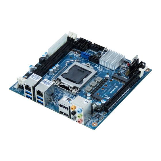
Page 30: Connector Locations
KTD-N0882-I Page 30 Connector Location Connector Locations KTQ87/mITX (KTH81/mITX) - frontside SATA4 DDR3 Slot 1 FEATURE SATA3 (KTQ87 only) USB10 SATA2 DDR3 Slot 2 COM2 USB11 SATA0 SATA5 FRONTPNL COM1 ATX24P Always On Load Default USB4 USB5 System temp. (U97) mSATA &... -
Page 31: Ktq87/Flex (Kth81/Flex) - Frontside
KTD-N0882-I Page 31 Connector Location KTQ87/Flex (KTH81/Flex) - frontside SATA4 SATA0 SATA2 SATA2 & SATA3 on Q87 only. DIMM4/2/3/1 SATA1 SATA5 SATA3 H81: SATA4 & SATA5 is SATA Gen.2 (DIMM4 & 2 only ATX24P FRONTPNL, USB10/11 Always On on KTQ87/Flex) USB6/7 Sys_Fan1 USB8/9... -
Page 32: Connector Definition
KTD-N0882-I Page 32 Connector Definition Connector Definition The following sections provide pin definitions and detailed description of all on-board connectors. The connector definitions follow the following notation: Column Description name Shows the pin-numbers in the connector. The graphical layout of the connector definition tables is made similar to the physical connectors. -
Page 33: Io-Area Connectors
KTD-N0882-I Page 33 IO-Area Connectors IO-Area Connectors DP Connectors (DP0, DP1, DP2) The DP (DisplayPort) connectors are based on standard DP type Foxconn 3VD51203-H7JJ-7H or similar. Note that DP2 only available on KTQ87. Signal Description Type Note Lane 0 (p) LVDS Lane 0 (n) LVDS... -
Page 34: Ethernet Connectors
KTD-N0882-I Page 34 IO-Area Connectors Ethernet Connectors The KTQ87/KTH81 supports two channels of 10/100/1000Mb Ethernet. First Ethernet connector (LAN1) is based on Intel® Clarkville i218LM/i218-V Gigabit PHY. The i218-LM (Q87) has AMT 9.0 support and the i218-V (H81) has no AMT support. Second Ethernet connector (LAN2) is based on Intel® Pearsonville i218AT PCI Express controller. -
Page 35: Usb Connectors (Io Area)
The KTQ87/mITX has total of 10 USB ports where four ports support USB 3.0 or USB 2.0 via Rear IO connectors. The KTH81/mITX has total of 10 USB ports where two ports support USB 3.0 or USB 2.0 via Rear IO connectors (USB port 2 &... -
Page 36: Usb Connector 0/1 (Usb0/1)
KTD-N0882-I Page 36 IO-Area Connectors USB Connector 0/1 (USB0/1) USB Ports 0 and 1 are mounted together with LAN2 port and supports USB3.0/USB2.0. Note Type Signal Signal Type Note USB1- USB1+ 5V/SB5V RX1- TX1+ RX1+ TX1- USB0- USB0+ 5V/SB5V RX0- TX0+ RX0+ TX0-... -
Page 37: Usb Connector 2/3 (Usb2/3)
KTD-N0882-I Page 37 IO-Area Connectors USB Connector 2/3 (USB2/3) USB Ports 2 and 3 are mounted together with LAN1 port and supports USB3.0/USB2.0. Note Type Signal Signal Type Note USB3- USB3+ 5V/SB5V RX3- TX3+ RX3+ TX3- USB2- USB2+ 5V/SB5V RX2- TX2+ RX2+ TX2-... -
Page 38: Audio Jack Connector Stack (Audio)
KTD-N0882-I Page 38 IO-Area Connectors Audio Jack Connector Stack (Audio) The on-board Audio circuit implements up to 8 Channel High Definition Audio via stacked audiojack connectors and via SPDIF connector, see SPDIF description. Interface is based on UAA (Universal Audio Architecture), featuring five 24-bit stereo DACs and three 20- bit stereo ADCs. -
Page 39: Internal Connectors
KTD-N0882-I Page 39 Internal Connectors Internal Connectors The KTQ87/KTH81 boards are designed to be supplied from a standard ATX (or BTX) power supply. Use of BTX supply is not required for operation, but may be required to drive high-power PCIe cards. Warning: Hot plugging any of the two power connectors is not allowed. -
Page 40: Fan Connectors (Cpu_Fan, Sys_Fan1, Sys_Fan2)
KTD-N0882-I Page 40 Internal Connectors Fan Connectors (CPU_Fan, SYS_Fan1, SYS_Fan2) The SYS_FAN1 and SYS_Fan2 can be used to power, control and monitor fans for chassis ventilation etc. The CPU_Fan is used for the connection of the FAN included in active CPU coolers. The 4pin header is recommended to be used for driving 4-wire type Fan in order to implement FAN speed control. -
Page 41: Ps/2 Keyboard And Mouse Connector (Kbd/Mse) (Ps2)
KTD-N0882-I Page 41 Internal Connectors PS/2 Keyboard and Mouse connector (KBD/MSE) (PS2) Attachment of a PS/2 keyboard/mouse can be done through the pinrow connector KBD/MSE (Flex boards only). Both interfaces utilize open-drain signalling with on-board pull-up. The PS/2 mouse and keyboard is supplied from SB5V when in standby mode in order to enable keyboard or mouse activity to bring the system out from power saving states. -
Page 42: Lvds Flat Panel Connector (Lvds)
KTD-N0882-I Page 42 Internal Connectors LVDS Flat Panel Connector (LVDS) The LVDS connector (Flex boards only) is based on 40 pole connector type Samtec SHF-120-01-F-D-SM-K- TR or similar. Note Type Signal Signal Type Note Max. 0.5A +12V +12V PWR Max. 0.5A Max. -
Page 43: Sata (Serial Ata) Disk Interface
KTD-N0882-I Page 43 Internal Connectors SATA (Serial ATA) Disk interface KTQ87 / KTH81 has integrated SATA Host controller (PCH in the Q87 / H81 chipset) which supports independent DMA operation on 6 / 4 ports. One device can be installed on each port, via point-to-point interface (SATA cable), for a maximum of 6 / 4 SATA devices. -
Page 44: Usb Connectors (Usb)
KTD-N0882-I Page 44 Internal Connectors USB Connectors (USB) The KTQ87 board contains two EHCI (Enhanced Host Controller Interface) host controllers (EHCI1 and EHCI2) and a XHCI (Extensible Host Controller Interface). The EHCI controllers support up to fourteen USB 2.0 ports allowing data transfers up to 480Mb/s and the XHCI controller supports up to six USB 3.0 ports allowing data transfers up to 5Gb/s. -
Page 45: Usb 4 & 5 (Usb4/5) (Usb1)
KTD-N0882-I Page 45 Internal Connectors USB 4 & 5 (USB4/5) (USB1) USB Ports 4 and 5 are supplied on the internal USB4/5 pinrow connector USB1. Note Type Signal Signal Type Note PWR 5V/SB5V 5V/SB5V PWR USB8- USB9- USB8+ USB9+ 9 10 USB 6 &... -
Page 46: Serial Com1 - Com2 Ports (Com1, Com2)
KTD-N0882-I Page 46 Internal Connectors Serial COM1 – COM2 Ports (COM1, COM2) Two RS232 serial ports are available on the KTQ87/KTH81. The typical definition of the signals in the COM ports is as follows: Signal Description Transmitted Data, sends data to the communications link. The signal is set to the marking state (- 12V) on hardware reset when the transmitter is empty or when loop mode operation is initiated. -
Page 47: Audio Connectors
KTD-N0882-I Page 47 Internal Connectors Audio Connectors The on-board Audio circuit implements 7.1+2 Channel High Definition Audio with UAA (Universal Audio Architecture), featuring five 24-bit stereo DACs and three 20-bit stereo ADCs. The following Audio connectors are available as Internal connectors. Headphone and Mic2 Headphone and Mic2 are accessible via Front Panel Connector, see Front Panel Connector description. -
Page 48: Front Panel Connector (Frontpnl) (J2)
KTD-N0882-I Page 48 Internal Connectors 7.10 Front Panel Connector (FRONTPNL) (J2) Pull Ioh/ Ioh/ Pull Note Type Signal Signal Type Note PWR USB10/11_5V USB10/11_5V PWR - USB10- USB11- USB10+ USB11+ PWR GND PWR - Headphone-L PWR +5V 11 12 PWR - 25/25mA O SATA_LED# 13 14... -
Page 49: Feature Connector (Feature) (J1)
KTD-N0882-I Page 49 Internal Connectors Feature Connector (Feature) (J1) 7.11 Note Pull U/D Ioh/Iol Type Signal Signal Type Ioh/Iol Pull U/D Note CASE_OPEN# SMBC /4mA 10K/ 25/25mA O SMBD /4mA 10K/ 25/25mA O PWR_OK EXT_BAT PWR - FAN3OUT FAN3IN PWR SB3V3 SB5V PWR - GPIO0... - Page 50 KTD-N0882-I Page 50 Internal Connectors Signal Description General Purpose Inputs / Output. These Signals may be controlled or monitored through GPIO0..17 the use of the KT-API-V2 (Application Programming Interface). (GPIO14 and GPIO16 not available, used internally) EGCLK Extend GPIO Clock signal EGAD Extend GPIO Address Data signal EGCS#...
-
Page 51: Load Default Bios Settings" (Load Default) (Cmos)
KTD-N0882-I Page 51 Internal Connectors 7.12 “Load Default BIOS Settings” (Load default) (CMOS) The “Load Default BIOS Settings” Jumper (J5) can be used to recover from incorrect BIOS settings. As an example, incorrect BIOS setting which causes the attached display not to turn on can be erased by this Jumper. -
Page 52: Always On" (Always On) (A_On)
KTD-N0882-I Page 52 Internal Connectors 7.13 “Always On” (Always On) (A_ON) The “Always On” can be used to implement hardware controlled Always ON by jumper. When “Always On” is selected, then the board will power up automatically when power is connected. The board can still be shut down by PWRBTN_IN# (power button in) activation (via Front Panel connector). -
Page 53: Spi Connector (Spi_Head)
KTD-N0882-I Page 53 Internal Connectors 7.14 SPI Connector (SPI_HEAD) The SPI Connector is normally not used. If however a SPI BIOS is connected via the SPI Connector then the board will attempt to boot from it. Note Pull U/D Ioh/Iol Type Signal Signal Type Ioh/Iol Pull U/D Note... -
Page 54: Xdp_Cpu (Debug Port For Cpu) (Xdp_Cpu)
KTD-N0882-I Page 54 Internal Connectors 7.16 XDP_CPU (Debug Port for CPU) (XDP_CPU) The XDP_CPU (Intel Debug Port for CPU) connector is not mounted and not supported. XDP connector layout (pads) is located on the backside of PCB and is prepared for the Samtec BSH-030-01-F-D-A-TR. Note Pull U/D Ioh/Iol Type Signal Signal... -
Page 55: Xdp_Pch (Debug Port For Chipset) (Xdp_Pch)
KTD-N0882-I Page 55 Internal Connectors 7.17 XDP_PCH (Debug Port for Chipset) (XDP_PCH) The XDP_PCH (Intel Debug Port for Chipset) connector is not mounted and not supported. XDP_PCH connector layout (pads) is located on the backside of PCB (below J35 connector on mITX version) and is prepared for the Samtec BSH-030-01-F-D-A-TR. -
Page 56: Slot Connectors (Pcie, Mpcie, Msata, Pci)
KTD-N0882-I Page 56 Slot Connectors Slot Connectors (PCIe, mPCIe, mSATA, PCI) PCIe Connectors The mITX boards supports one PCIex16 (16-lanes), one miniPCIe and one mSATA in mPCIe slot. The Flex boards supports one PCIex16 (16-lanes), one PCIex2 (2-lanes) in a x16 slot and one PCIex1 slot. The PCIex16 port can be used for external PCI Express cards inclusive graphics card. - Page 57 KTD-N0882-I Page 57 Slot Connectors PEG_TXP[2] PEG_TXN[2] PEG_RXP[2] PEG_RXN[2] PEG_TXP[3] PEG_TXN[3] PEG_RXP[3] PEG_RXN[3] CLKREQ PEG_TXP[4] PEG_TXN[4] PEG_RXP[4] PEG_RXN[4] PEG_TXP[5] PEG_TXN[5] PEG_RXP[5] PEG_RXN[5] PEG_TXP[6] PEG_TXN[6] PEG_RXP[6] PEG_RXN[6] PEG_TXP[7] PEG_TXN[7] PEG_RXP[7] CLKREQ PEG_RXN[7] PEG_TXP[8] PEG_TXN[8] PEG_RXP[8] PEG_RXN[8] PEG_TXP[9] PEG_TXN[9] PEG_RXP[9] PEG_RXN[9] PEG_TXP[10] PEG_TXN[10] PEG_RXP[10] PEG_RXN[10]...
-
Page 58: Pci-Express X2 Connector (Pciex2) In X16 Slot (Pcie2)
KTD-N0882-I Page 58 Slot Connectors PCI-Express x2 Connector (PCIex2) in x16 slot (PCIE2) (Flex boards only). Note Type Signal Signal Type Note +12V +12V +12V +12V +12V SMB_CLK SMB_DATA +3V3 +3V3 SB3V3 +3V3 WAKE# RST# PCIE_x16 CLK PEG_TXP[0] PCIE_x16 CLK# PEG_TXN[0] PEG_RXP[0] CLKREQ... -
Page 59: Pci-Express X1 Connector (Pciex1) (Pcie3)
KTD-N0882-I Page 59 Slot Connectors CLKREQ PCI-Express x1 Connector (PCIex1) (PCIE3) Only on Flex boards. Note Type Signal PIN# Signal Type Note +12V +12V +12V +12V +12V SMB_CLK SMB_DATA +3V3 +3V3 SB3V3 +3V3 WAKE# RST# PCIE CLK PCIE_TXP PCIE CLK# PCIE_TXN PCIE_RXP PCIE_RXN... -
Page 60: Minipci-Express Mpcie (Mpcie)
KTD-N0882-I Page 60 Slot Connectors miniPCI-Express mPCIe (MPCIE) (mITX boards only). The miniPCIe port supports mPCIe and USB 2.0 cards (not mSATA). Note Type Signal Signal Type Note WAKE# +3V3 +1.5V CLKREQ# PCIE_mini CLK# PCIE_mini CLK W_Disable# RST# PCIE_RXN +3V3 Dual PCIE_RXP +1.5V SMB_CLK... -
Page 61: Msata (Msata)
KTD-N0882-I Page 61 Slot Connectors mSATA (MSATA) (mITX boards only). The mSATA port (in mPCIe express connector) supports mSATA and USB 2.0 cards (not PCIe cards). Note Type Signal Signal Type Note WAKE# +3V3 +1.5V CLKREQ# PCIE_mini CLK# PCIE_mini CLK W_Disable# RST# PCIE_RXN... -
Page 62: Pci Slot Connector
KTD-N0882-I Page 62 Slot Connectors PCI Slot Connector Flex board only. Terminal Note Type Signal Signal Type Note -12V TRST# +12V INTA# INTB# INTC# INTD# +5V (I/O) PWR GNT3# RST# CLKB +5V (I/O) PWR GNT0# REQ0# PWR +5V (I/O) PME# AD31 AD30 AD29... -
Page 63: Signal Description - Pci Slot Connector
KTD-N0882-I Page 63 Slot Connectors Signal Description – PCI Slot Connector SYSTEM PINS Clock provides timing for all transactions on PCI and is an input to every PCI device. All other PCI signals, except RST#, INTA#, INTB#, INTC#, and INTD#, are sampled on the risingedge of CLK and all other timing parameters are defined with respect to this edge. -
Page 64: Ktq81/Flex & Kth81/Flex Pci Irq & Int Routing
KTD-N0882-I Page 64 Slot Connectors ARBITRATION PINS (BUS MASTERS ONLY) Request indicates to the arbiter that this agent desires use of the bus. This is a point to point signal. Every master REQ# has its own REQ# which must be tri-stated while RST# is asserted. Grant indicates to the agent that access to the bus has been granted. -
Page 65: On-Board - & Mating Connector Types
Note: In above table, more than one connector can be listed for each type of on-board connector, if they all have same fit, form and function and are approved by Kontron as an alternative. Please notice that standard connectors like DP, PCI, PCIe, miniPCIe, Audio Jack, Ethernet and USB are not included in the list. -
Page 66: 10 Bios
KTD-N0882-I Page 66 BIOS - Main 10 BIOS The BIOS Setup is used to view and configure BIOS settings for the board. The BIOS Setup is accessed by pressing the <Del> -key after the Power-On Self-Test (POST) memory test begins and before the operating system boot begins. -
Page 67: System Information
KTD-N0882-I Page 67 BIOS - Main System Information Phoenix SecureCore Technology Setup Main System Information BIOS Version ADE-606A KTQ87118 Build Time 06/30/2014 Processor Type Genuine Intel ® CPU 0000 @2.60GHz Processor Speed 2.600 GHz System Memory Speed 1333 MHz L2 Cache RAM 256 KB Total Memory 4096 MB... -
Page 68: Boot Features
KTD-N0882-I Page 68 BIOS - Main Boot Features Phoenix SecureCore Technology Setup Main Boot Features Item Specific Help NumLock: [On] Select Power-on state for NumLock. Timeout [ 2] CSM Support [Yes] Diagnostic Splash Screen [Disabled] Diagnostic Summary Screen [Disabled] UEFI Boot [Disabled] Legacy Boot [Enabled]... -
Page 69: Error Manager
KTD-N0882-I Page 69 BIOS - Main Error Manager Phoenix SecureCore Technology Setup Main Error Manager Item Specific Help View Error Manager Log [Enter] Display Error Manager Log Clear Error Manager Log [Enter] information. Help ↑↓ Select Item Change Values Setup Defaults Exit ←→... -
Page 70: 10.2 Advanced
KTD-N0882-I Page 70 BIOS - Advanced 10.2 Advanced Phoenix SecureCore Technology Setup Main Advanced Security Boot Exit Item Specific Help Select Language [English] ► Silicon Information Select Language. ► Processor Configuration ► HDD Configuration ► System Agent (SA) Configuration ► South Bridge Configuration ►... -
Page 71: Silicon Information
KTD-N0882-I Page 71 BIOS - Advanced Silicon Information Phoenix SecureCore Technology Setup Advanced Genuine Intel ® CPU 0000 @ 2.60GHz FAMILY Gen Intel Core Processor MODEL 22nm Haswell Desktop CPUID 306C2 CPU REV. B0 Stepping PATCH ID FFFF0006 CORE FREQ. 2.60GHz L1 Cache 64 KB... -
Page 72: Processor Configuration
KTD-N0882-I Page 72 BIOS - Advanced Processor Configuration Phoenix SecureCore Technology Setup Advanced Processor Configuration Item Specific Help Active Processor Cores [All] Number of cores to enable in each Intel ® HT Technology [Enabled] processor package. Enable XD [Enabled] Intel ® Virtualization Technology [Enabled] Intel ®... -
Page 73: Hdd Configuration
KTD-N0882-I Page 73 BIOS - Advanced HDD Configuration Phoenix SecureCore Technology Setup Advanced HDD Configuration Item Specific Help SATA Device [Enabled] Enable/Disable SATA Device. Interface Combination [ACHI] Serial ATA Port 0 Not Installed or the port is disabled Port Enable [Enabled] Hot Plug [Disabled]... -
Page 74: System Agent (Sa) Configuration
KTD-N0882-I Page 74 BIOS - Advanced System Agent (SA) Configuration Phoenix SecureCore Technology Setup Advanced System Agent (SA) Configuration Item Specific Help ► Graphics Configuration Press Enter to access the Graphics ► PEG Port Configuration Configuration menu. Help ↑↓ Select Item Change Values Setup Defaults Exit... - Page 75 KTD-N0882-I Page 75 BIOS - Advanced Graphics Configuration Phoenix SecureCore Technology Setup Advanced Graphics Configuration Item Specific Help Primary Display Selection [Auto] Select the primary display device. Internal Graphics [Auto] DVMT Pre-Allocated [32MB] DVMT Total Gfx Mem [256MB] ► LVDS Configuration ►...
- Page 76 KTD-N0882-I Page 76 BIOS - Advanced LVDS Configuration Phoenix SecureCore Technology Setup Advanced LVDS Configuration Item Specific Help Switch mode [LVDS] Switch Display Port-D between LVDS Voltage [3.3V] LVDS or DP. Panel Color Depth [24 bpp] Brightness Level [100%] Panel Driver [HW default] Help ↑↓...
- Page 77 KTD-N0882-I Page 77 BIOS - Advanced IGD Configuration Phoenix SecureCore Technology Setup Advanced IGD Configuration Item Specific Help IGD – Boot Type [VBIOS Default] Select the Video Device activated during POST. This has no effect if external graphics are present. Help ↑↓...
- Page 78 KTD-N0882-I Page 78 BIOS - Advanced PEG Port Configuration Phoenix SecureCore Technology Setup Advanced PEG Port Configuration Item Specific Help PEG –Gen X [Auto] Configure PEG0 B0:D1:F0 Speed. PEG1 – Gen X [Auto] PEG2 – Gen X [Auto] Always Enable PEG [Enabled] PEG ASPM [Disabled]...
-
Page 79: South Bridge Configuration
KTD-N0882-I Page 79 BIOS - Advanced South Bridge Configuration Phoenix SecureCore Technology Setup Advanced South Bridge Configuration Item Specific Help Port 80h Cycles [LPC Bus] Control where the Port 80h cycles State After G3 [State S0] are sent. PS/2 Legacy device wake [Wake from S3 Only] ►... - Page 80 KTD-N0882-I Page 80 BIOS - Advanced SB PCI Express Config Phoenix SecureCore Technology Setup Advanced SB PCI Express Config Item Specific Help PCI Express Port assigned to LAN 2 Control the PCI Express Root Port. ► PCI Express Port 1 Config ►...
- Page 81 KTD-N0882-I Page 81 BIOS - Advanced PCI Express Root Port 1 (3, 4 & 5) Phoenix SecureCore Technology Setup Advanced PCI Express Root Port 1 (3, 4 & 5) Item Specific Help PCI Express Root Port 1 (3&4) [Enabled] Control the PCI Express Root Port. PCIe Speed [Auto] Help...
- Page 82 KTD-N0882-I Page 82 BIOS - Advanced SB USB Configuration Phoenix SecureCore Technology Setup Advanced SB USB Configuration Item Specific Help xHCI Mode [Smart Auto] Mode of operation of xHCI controller. EHCI2 [Enabled] USB Per-Port Disable Control [Disabled] Help ↑↓ Select Item Change Values Setup Defaults Exit...
- Page 83 KTD-N0882-I Page 83 BIOS - Advanced SB Azalia Configuration Phoenix SecureCore Technology Setup Advanced SB Azalia Configuration Item Specific Help Azalia [Auto] Control Detection of the Azalia device. Help ↑↓ Select Item Change Values Setup Defaults Exit ←→ Select Menu Enter Select Sub-Menu...
-
Page 84: Lan Configuration
KTD-N0882-I Page 84 BIOS - Advanced LAN Configuration Phoenix SecureCore Technology Setup Advanced LAN Configuration Item Specific Help LAN Configuration Control the Ethernet Devices and PXE boot. ETH1 Configuration (Left) [Enabled] Wake on LAN [Enabled] MAC Address & Link status : [00E0F42C4E01-] ETH2 Configuration (Right) [With PXE boot]... -
Page 85: Pci Bridge Configuration
KTD-N0882-I Page 85 BIOS - Advanced PCI bridge Configuration Phoenix SecureCore Technology Setup Advanced PCI bridge Configuration Item Specific Help Prefetch Agent Control Request Length Limit. Determines Cache Request Length Limit [128 Bytes] the number of bytes in the thread Cache Request Count Limit [ 4] that the pre-fetchagent will read for... - Page 86 KTD-N0882-I Page 86 BIOS - Advanced Function Selection Description 64 Bytes 128 Bytes 256 Bytes Request Length Limit. Determines the number of 512 Bytes Cache Request Length Limit bytes in the thread that the pre-fetchagent will 1Kbytes read for that thread. 2Kbytes 4Kbytes 8Kbytes...
-
Page 87: Hardware Health Configuration
KTD-N0882-I Page 87 BIOS - Advanced Hardware Health Configuration Phoenix SecureCore Technology Setup Advanced Hardware Health Configuration Item Specific Help Hardware Health Configuration Use external connected sensor instead of onboard. System Temperature [ 42ºC/107ºF] System Temperature 2 [ 42ºC/107ºF] CPU Temperature [ 50.46ºC/122ºF] System Fan Speed 0 RPM]... - Page 88 KTD-N0882-I Page 88 BIOS - Advanced Function Selection Description System Temperature Location Onboard Use external connected sensor instead of LM75 @ 0x90 (Note 1) onboard. Disabled Disabled = Full speed. Fan Cruise Control (Note 2) Thermal Thermal: Regulate according to specified ºC. Speed Speed: Regulate according to specified RPM.
-
Page 89: Smbios Event Log
KTD-N0882-I Page 89 BIOS - Advanced SMBIOS Event Log Phoenix SecureCore Technology Setup Advanced SMBIOS Event Log Item Specific Help Event LOG Validity Valid Enable/Disable Event Log. Event Log Capacity Space Available Event Log [Enabled] ► View SMBIOS event log Mark SMBIOS as read [Enter] Clears SMBIOS events... -
Page 90: Amt Configuration
KTD-N0882-I Page 90 BIOS - Advanced AMT Configuration Phoenix SecureCore Technology Setup Advanced AMT Configuration Item Specific Help Intel ® AMT [Enabled] Enable/Disable Intel ® Active Enter Intel ® MEBx Setup [Disabled] Management Technology BIOS Un-Configure ME [Disabled] Extension. Note: iAMT H/W is always enabled. This option just controls the BIOS extension execution. - Page 91 KTD-N0882-I Page 91 BIOS - Advanced MEBx Configuration Phoenix SecureCore Technology Setup Advanced MEBx Configuration Item Specific Help Enter Intel ® MEBx Setup [Disabled] Enter Intel ® MEBx Setup on the Un-Configure ME [Disabled] next boot. Hide Un-Configure ME Confirmation [Disabled] MEBx Debug Message output [Disabled]...
- Page 92 KTD-N0882-I Page 92 BIOS - Advanced MEBx Resolution Setting Phoenix SecureCore Technology Setup Advanced MEBx Resolution Setting Item Specific Help Non-UI Text Mode resolution [Auto] Text Mode resolution used by MEBx UI Text Mode resolution [Auto] for messages outside MEBx User Graphic Mode resolution [Auto] Interface.
-
Page 93: Me Configuration
KTD-N0882-I Page 93 BIOS - Advanced ME Configuration Phoenix SecureCore Technology Setup Advanced ME Configuration Item Specific Help ME FW Version 9.1.2.1010 Enable/Disable Intel ® Management ME Firmware Intel ® ME 5MB firmware Engine. Intel ® ME [Enabled] Intel ® AT [Enabled] Help ↑↓... -
Page 94: Intel ® Rapid Start Technology
KTD-N0882-I Page 94 BIOS - Advanced Intel ® Rapid Start Technology Phoenix SecureCore Technology Setup Advanced Intel ® Rapid Start Technology Item Specific Help Intel ® Rapid Start Technology Support [Disabled] Intel ® Rapid Start Technology. Help ↑↓ Select Item Change Values Setup Defaults Exit... -
Page 95: 10.3 Security
KTD-N0882-I Page 95 BIOS - Security 10.3 Security Phoenix SecureCore Technology Setup Main Advanced Security Boot Exit Item Specific Help Supervisor Password is: Cleared User Password is: Cleared Set or clear the Supervisor account’s password. Set Supervisor Password [Enter] Supervisor Hint String Set User Password [Enter] User Hint String... -
Page 96: Tpm Configuration
KTD-N0882-I Page 96 BIOS - Security TPM Configuration Phoenix SecureCore Technology Setup Security TPM Configuration Item Specific Help Enact TPM Action. Note: Most Current TPM State [Enabled and Activate] TPM actions require TPM to be TPM Action Change] Enabled to take effect. Omit Boot Measurements [Disabled] Help... -
Page 97: Boot
KTD-N0882-I Page 97 BIOS - Boot 10.4 Boot Phoenix SecureCore Technology Setup Boot Item Specific Help Boot Priority Order 1. USB HDD: Keys used to view or configure 2. USB CD: devices: ↑ and ↓ arrows Select a 3. USB FDD: device. -
Page 98: Exit
KTD-N0882-I Page 98 BIOS - Exit 10.5 Exit Phoenix SecureCore Technology Setup Exit Item Specific Help Exit Saving Changes Exit Discarding Changes Equal to F10, save all changes of Load Setup Defaults all menus, then exit setup Discard Changes configure driver. Finally resets Save Changes the system automatically.
Need help?
Do you have a question about the KTH81/mITX and is the answer not in the manual?
Questions and answers