Table of Contents
Advertisement
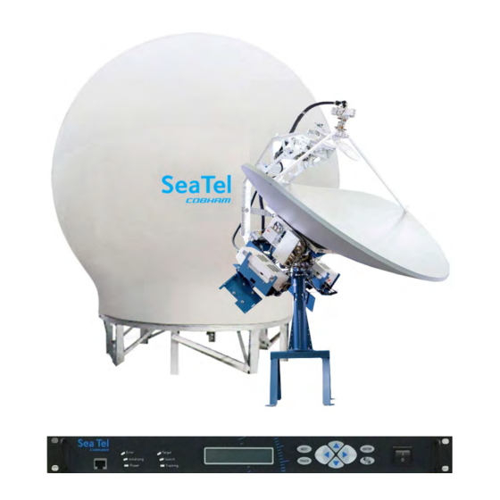
Sea Tel 2400 Dual Band Satellite Antenna
Installation Manual
This technical data is subject to US Government export control in accordance with the
Export Administration Regulations. Export of this data to any foreign country, or disclosure
of this data to a Non-US person, may be a violation of Federal law.
Sea Tel, Inc.
(trading as Cobham SATCOM)
4030 Nelson Avenue
Concord, CA 94520
Tel: +1 (925) 798-7979
Fax: +1 (925) 798-7986
Web:
http://www.cobham.com/satcom
November 20, 2019
EAR Controlled - ECCN EAR99
EAR Controlled - ECCN EAR99
Thrane & Thrane A/S
(trading as Cobham SATCOM)
Lundtoftegaardsvej 93 D, 2800 Kgs.
Lyngby, Denmark
Tel: +45 3955 8800
Fax: +45 3955 8888
satcom.ohc@cobham.com
Email:
Document. No. 99-167970-B
Advertisement
Table of Contents

Related Manuals for COBHAM Sea Tel 2400


Summary of Contents for COBHAM Sea Tel 2400
- Page 1 Sea Tel 2400 Dual Band Satellite Antenna Installation Manual EAR Controlled - ECCN EAR99 This technical data is subject to US Government export control in accordance with the Export Administration Regulations. Export of this data to any foreign country, or disclosure of this data to a Non-US person, may be a violation of Federal law.
- Page 2 Sea Tel, Inc. This document may not be reproduced or distributed in any form, without prior written consent of Sea Tel, Inc. The information in this document is subject to change without notice. Sea Tel Inc. is also doing business as Cobham SATCOM.
- Page 3 Sea Tel Inc. 4030 Nelson Ave., Concord California, 94520, USA T: +1 (925) 798-7979 F: +1 (925) 798-7986 RED Declaration of Conformity Sea Tel Inc. declares under our sole responsibility that the products identified below are in compliance with the requirements of: RED Directive 2014/53/EU concerning maritime Radio Equipment as described in the harmonized standards listed below and the mutual recognition of their conformity.
- Page 4 Sea Tel Inc. 4030 Nelson Ave., Concord California, 94520, USA T: +1 (925) 798-7979 F: +1 (925) 798-7986 RED Declaration of Conformity Sea Tel Inc. declares under our sole responsibility that the products identified below are in conformity with the requirements of: RED Directive 2014/53/EU concerning maritime Radio Equipment as described in the harmonized standards listed below and the mutual recognition of their conformity.
- Page 5 0.2 degrees, thus meeting the requirements of § 25.221 (a)(1)(iii). Sea Tel maintains all relevant test data, which is available upon request, to verify these declarations. 4/16/2013 Peter Blaney, Chief Engineer Date Cobham – SATCOM Sea Tel Products. Document Number 130449 Revision F...
- Page 6 Sea Tel Inc. 4030 Nelson Ave., Concord California, 94520, USA T: +1 (925) 798-7979 F: +1 (925) 798-7986 FCC Declaration of Conformity Sea Tel, Inc. designs, develops, manufactures and services marine stabilized antenna systems for satellite communication at sea. These products are in turn used by our customers as part of their Ku- band Earth Station on Vessels (ESV) networks.
-
Page 7: Table Of Contents
Table of Contents Sea Tel 2400 Dual Band C/Ku 1. SAFETY ..........................................1-1 2. INTRODUCTION ......................................2-1 2.1.................................. 2-1 ENERAL YSTEM ESCRIPTION 2.2........................................... 2-1 URPOSE 2.3................................... 2-1 THER NPUTS TO THE YSTEM 2.4....................................2-1 YSTEM OMPONENTS 2.5. - Page 8 Sea Tel 2400 Dual Band C/Ku Table of Contents 4.6.3. Remove stow Straps ................................4-28 4.6.4. ADE Final Checks ................................... 4-28 4.7............................4-29 NSTALLING THE ELOW ECKS QUIPMENT 4.7.1. General Cautions & Warnings ............................4-29 4.7.2. Connecting the BDE AC Power Cables ........................4-29 4.7.3.
- Page 9 Table of Contents Sea Tel 2400 Dual Band C/Ku 14.1. C ..................................14-2 YBER ECURITY AUTION 15. INSTALLATION TROUBLESHOOTING ............................15-1 15.1. T ........................15-1 ROUBLESHOOTING HIPS OMPASS PROBLEMS 15.1.1. STEP-BY-STEP ................................... 15-1 15.1.2. 1:1 SYNCHRO .................................... 15-2 15.1.3. 360:1 Synchro ................................... 15-2 16.
- Page 10 Sea Tel 2400 Dual Band C/Ku Table of Contents This Page Intentionally Left Blank EAR Controlled - ECCN EAR99...
-
Page 11: Safety
Service User access to the interior of the antenna control unit (ACU) is prohibited. Only a technician authorized by Cobham SATCOM may perform service - failure to comply with this rule will void the warranty. Access to the interior of the Above Deck Equipment (ADE) is allowed. - Page 12 Safety Sea Tel 2400 Dual Band C/Ku This Page Intentionally Left Blank EAR Controlled - ECCN EAR99...
-
Page 13: Introduction
Sea Tel 2400 Dual Band C/Ku Introduction Introduction WARNI NG: RF Radiation Hazard - This stabilized antenna system is designed to be used with transmit/receive equipment manufactured by others. Refer to the documentation supplied by the manufacturer which will describe potential hazards, including exposure to RF radiation, associated with the improper use of the transmit/receive equipment. -
Page 14: Dual Antenna Configuration
Introduction Sea Tel 2400 Dual Band C/Ku 2.5. Dual Antenna Configuration Sometimes, due to very large blockage conditions, you may need to install a dual antenna configuration to provide uninterrupted services. Two full antenna systems are installed and the MXP control outputs are connected to an arbitrator switch panel which then is connected to the below decks equipment. -
Page 15: Open Amip™, Roam Or Vacp
Sea Tel 2400 Dual Band C/Ku Introduction 2.8. OpenAMI P™, ROAM or VACP These each have standardized language incorporated into their (iDirect, Comtech & STM) modems which communicates automatic beam switching settings from their options file to the Sea Tel ACU(s). This provides the network a means of controlling automatic beam switching by the settings in the options file in the remote modem. - Page 16 Introduction Sea Tel 2400 Dual Band C/Ku This Page Intentionally Left Blank EAR Controlled - ECCN EAR99...
-
Page 17: Site Survey
Sea Tel 2400 Dual Band C/Ku Site Survey Site Survey There are three objective of the site survey. The first is to find the best place to mount the antenna and the BDE. The second is to identify the length and routing of the cables and any other items or materials that are required to install the system. -
Page 18: Mounting Foundation
Site Survey Sea Tel 2400 Dual Band C/Ku 3.3. Mounting Foundation 3.3.1. Mounting on Deck or Deckhouse While mounting the ADE on a mast is a common solution to elevate the ADE far enough above the various obstructions, sometimes the best mounting position is on a deck or deckhouse top. These installations are inherently stiffer than a mast installation as the design of the deck/deckhouse structure is prescribed by the ship’s classification society. -
Page 19: Mast Configurations
Sea Tel 2400 Dual Band C/Ku Site Survey In some installations, though, the combination of mounting height, fore-aft location and ship motion can impart significant accelerations on the entire ADE. Installations where the ADE is situated high on the ship – usually at the top of a mast –... -
Page 20: Vertical Masts
Site Survey Sea Tel 2400 Dual Band C/Ku 3.5.1. Vertical Masts Vertical masts are a very ancient and common mast design. In essence, it is the mast derived from the sailing mast and adapted for mounting the ever-increasing array of antennae which ships need to communicate with the world. -
Page 21: Truss Mast
Sea Tel 2400 Dual Band C/Ku Site Survey 3.5.4. Truss Mast Truss masts are a variant on the girder mast concept. Rather than a pair of columns supporting a girder beam, the construction is a framework of tubular members supporting a platform on which the antennae and other equipment are mounted. -
Page 22: Antenna Power Cable
Site Survey Sea Tel 2400 Dual Band C/Ku Be sure that the shield(s) of the coaxes are not in contact with the ships ground. The coaxes must be of adequate conductor cross-sectional surface area for the length of the cable run and that the loop resistance of the cable run is less than 2.0 ohms. -
Page 23: Installation In 144" Radome
Sea Tel 2400 Dual Band C/Ku Installation in 144” Radome Installation in 144” Radome I t is highly This section contains instructions for unpacking, final assembly and installation of the equipment. recommended that final assembly and installation of the Antenna system be performed by trained technicians. -
Page 24: Separate The Base Frame & Radome Crates
Installation in 144” Radome Sea Tel 2400 Dual Band C/Ku A hoist, or small crane, is needed to assemble these sub-assemblies to form the final ADE Assembly. As an example, you might sub-assemble everything on the pier where the ship will tie up, then use the crane to put the sub-assemblies together and lift the whole ADE up to the mounting location on the ship. -
Page 25: Assembling The Above Decks Equipment (Ade)
Sea Tel 2400 Dual Band C/Ku Installation in 144” Radome CAUTION: The baseframe crate weighs 650 lbs. Do NOT attempt to move it or lay it down by hand. Use a forklift to lay the crate down and move it, as described in the following steps. -
Page 26: Base Frame
Installation in 144” Radome Sea Tel 2400 Dual Band C/Ku 4.4.1. Base Frame To open and prepare the Base Frame use the following procedure. Remove the screws around 3 sides of the perimeter of the base of the crate. Leave this side (with the... -
Page 27: Marine Air Conditioner (Internal)
Sea Tel 2400 Dual Band C/Ku Installation in 144” Radome To remove the base frame from the pallet, remove the 4 lag bolts from the FORE & AFT legs. Remove the 4 lag bolts from the PORT & STARBOARD legs (bolts are up through the pallet with flat, lock &... -
Page 28: Pedestal & Reflector
Installation in 144” Radome Sea Tel 2400 Dual Band C/Ku Prepare basepan per document 97-161542-A01 Hardware Kit, Mechanical, Internal AC (provided in the kit). Install the Drain Hose Strain Relief. Install 2 long strips of foam material to the exposed metal surfaces above & below the 2 vertical Bottom Vent openings. - Page 29 Sea Tel 2400 Dual Band C/Ku Installation in 144” Radome Remove the screws around perimeter of the removable panel of the crate. Remove the screws around perimeter of the 3 remaining sides at the base of the crate. To avoid damaging the feed...
- Page 30 Installation in 144” Radome Sea Tel 2400 Dual Band C/Ku Cut the bands from and remove the Hardware Kit, BDE Kit, MXP, C-Band Feed and Marine Air Conditioner boxes. Move these boxes to a location where they will be protected until you are ready to install the below decks equipment.
- Page 31 Sea Tel 2400 Dual Band C/Ku Installation in 144” Radome 17. There is an AC Power Strip mounted on the sawhorse. When the Az Post/Sawhorse is installed on the base frame this AC Power Strip should be orientated to the left of the base hatch.
- Page 32 Installation in 144” Radome Sea Tel 2400 Dual Band C/Ku 27. Open C-Band feed box. 28. Orient and seat the C-Band feed into the scalar plate. 29. Rotate the feed to align the Linear drive motor directly over the lower left strut.
- Page 33 Sea Tel 2400 Dual Band C/Ku Installation in 144” Radome 35. Route the C-Band feed harness from the left side of the frame (as shown in this picture) up over the top of the feed looping around the right and underside of the feed.
- Page 34 Installation in 144” Radome Sea Tel 2400 Dual Band C/Ku 48. Remove the 4 nylock nuts from the bolts that pass up through the wood and lower isolation plate. 49. Discard this hardware. 50. Remove the 4 bolts in the U-...
- Page 35 Sea Tel 2400 Dual Band C/Ku Installation in 144” Radome 56. Slowly & carefully lift the pedestal & reflector assembly up, guiding the spring and cables, up out of the wooden frame. 57. Hold the pedestal & reflector assembly above the top of the AZ Post.
- Page 36 Installation in 144” Radome Sea Tel 2400 Dual Band C/Ku 59. Carefully guide the cables & isolation spring down through the top of the Az post as the pedestal & reflector assembly is lowered. 60. Hold the pedestal & reflector assembly just above the top of the AZ Post.
- Page 37 Sea Tel 2400 Dual Band C/Ku Installation in 144” Radome 64. Align the 4 mounting holes in the lower isolation plate to the holes in the top of the AZ Post. 65. Lower the pedestal & reflector assembly to be on the top of the AZ Post, 66.
- Page 38 Installation in 144” Radome Sea Tel 2400 Dual Band C/Ku 74. Install ratchet straps (provided in the antenna stow kit) by hooking into the elevation beams and the sawhorse. 75. Tighten straps to restrain movement of the antenna. The pedestal & reflector assembly is now installed on the base frame assembly.
-
Page 39: Open The Radome Crate
Sea Tel 2400 Dual Band C/Ku Installation in 144” Radome 4.4.4. Open the Radome Crate We recommend that you place the Radome Crate in the area that you have chosen to assemble the Radome onto the base frame. This is the Radome crate. -
Page 40: Assembling The Lower Radome Panels
Installation in 144” Radome Sea Tel 2400 Dual Band C/Ku Remove the straps that restrain the radome cap. Leave the radome cap on the pallet with the radome panels for use during the radome assembly. Use diagonal cutters, or shears, to cut the bands that restrain the Hardware kit in the crate. - Page 41 Sea Tel 2400 Dual Band C/Ku Installation in 144” Radome NOTE: It is extremely important to assure that the flanges are properly aligned before the bolts are tightened and kept in alignment as the hardware is aligned. This is necessary for the inside clearance and the outside aesthetic appearance of the radome.
-
Page 42: Sub-Assemble The Upper Panels Of The 144" Radome Assembly
Installation in 144” Radome Sea Tel 2400 Dual Band C/Ku Use small wedges to open a vertical seam wide enough to install a good bead of silicone caulk. Working from top to bottom apply Loctite to and then firmly tighten all of the bolts in that seam (smaller dual beads of caulking can be applied from outside and inside if you prefer). - Page 43 Sea Tel 2400 Dual Band C/Ku Installation in 144” Radome Only 2 people are required to sub-assemble the top of the radome. On a flat surface, adjoin two panels and loosely install a bolt/nut high, mid and low in the adjoined flange.
- Page 44 Installation in 144” Radome Sea Tel 2400 Dual Band C/Ku Open each seam wide enough to install a good bead of silicone caulk. Working from top to bottom apply Loctite to and then firmly tighten all of the bolts in that seam (smaller dual beads of caulking can be applied from outside and inside if you prefer).
-
Page 45: Close The 144" Radome Assembly
Sea Tel 2400 Dual Band C/Ku Installation in 144” Radome 19. Install a second bolt and fender washer down through the hole on the other side of the vertical seam, through the slot on that side of the bracket and tighten a nut on the... -
Page 46: Preparing To Hoist The Ade
Installation in 144” Radome Sea Tel 2400 Dual Band C/Ku NOTE: It is extremely important to assure that the flanges are properly aligned before the bolts are tightened and kept in alignment as the hardware is aligned. This is necessary for the inside clearance and the outside aesthetic appearance of the radome. -
Page 47: Installing The Ade
Sea Tel 2400 Dual Band C/Ku Installation in 144” Radome If not already done, enter the ADE and stow the antenna pedestal using the Stow Kit (provided) and the instruction in the Maintenance section of the antenna manual. Attach the swivel eye-bolts of the Lift-It 144”... - Page 48 Installation in 144” Radome Sea Tel 2400 Dual Band C/Ku Use an appropriately sized hole saw to provide holes in the desired location of the base pan where the cables will enter the radome. Insert a strain relief up from the underside of the radome into one of the holes in the base of the radome.
- Page 49 Sea Tel 2400 Dual Band C/Ku Installation in 144” Radome NOTE: Marine Air Conditioner - Minimum gauge for the AC Power conductors should not be smaller than 12 AWG, even for a short cable run. 17. Route the AC Power cable through one of the compression caps, the washer, the rubber stopper and the body of the strain relief and into the base of the radome.
-
Page 50: Remove Stow Straps
Installation in 144” Radome Sea Tel 2400 Dual Band C/Ku 36. At the Marine Air Conditioner, cut the cable ties on the 2 cables that exit the side of the unit. 37. Unscrew the top cap and compression and route the AC UNIT INPUT power cable through them. -
Page 51: Installing The Below Decks Equipment
Sea Tel 2400 Dual Band C/Ku Installation in 144” Radome 4.7. I nstalling the Below Decks Equipment Connect this equipment as shown in the System Block Diagram. Install the equipment in a standard 19 inch equipment rack or other suitable location. Optional slide rails are available for the Sea Tel MXP. - Page 52 Installation in 144” Radome Sea Tel 2400 Dual Band C/Ku 4.7.3.11. J10D OBM RJ-45 Serial M&C connection to Out of Band Management equipment, if used. 4.7.3.12. J11 SBS/Synchro Gyro Terminal Strip for SBS or Synchro Gyro Compass interface connections. Wiring is:...
-
Page 53: Other Bde Connections
Sea Tel 2400 Dual Band C/Ku Installation in 144” Radome 4.7.3.14. J13 NMEA 0183 GYRO/GPS Compass NMEA 0183 I/O connections. The +12 VDC output is only intended to power a very low current consumption device, do NOT exceed 125ma MAX. Wiring is:... -
Page 54: Electrical - Double Check Wiring Connections
Installation in 144” Radome Sea Tel 2400 Dual Band C/Ku 4.8.2. Electrical - Double check wiring connections Double check all your connections to assure that it is safe to energize the equipment. 4.9. Setup - Media Xchange Point™ (MXP) Now that you have installed the hardware, you will need to setup, calibrate and commission the antenna. -
Page 55: Configuring A Computer For The Mxp
Sea Tel 2400 Dual Band C/Ku Configuring a Computer for the MXP Configuring a Computer for the MXP The first thing you need to do is to configure your computer so that it will display the MXP screens. Follow these instructions to accomplish that. - Page 56 Configuring a Computer for the MXP Sea Tel 2400 Dual Band C/Ku Click on “View network status and tasks”. Click “Change adapter settings”. Click on “Local Area Connection.” Click on “Properties”. EAR Controlled - ECCN EAR99...
- Page 57 Sea Tel 2400 Dual Band C/Ku Configuring a Computer for the MXP Double-Click on “Internet Protocol Version 4 (IPv4)”. 10. Click on “Use the following IP address: 11. In the IP Address boxes, enter “10.1.1.102” (This is for the IP address of your computer).
- Page 58 Configuring a Computer for the MXP Sea Tel 2400 Dual Band C/Ku 14. Back at the Local Area Connection Properties screen, click the “OK” button. 15. Click the “Close” button. 16. Close the Control Panel. 17. Open your browser, and enter the URL: “10.1.1.100”.
-
Page 59: Cyber Security Caution
Sea Tel 2400 Dual Band C/Ku Configuring a Computer for the MXP 18. At the log in screen enter the user name (Dealer, SysAdmin, or User). Contact Sea Tel Service for the password. 19. After you log in you will see the System Status screen 5.1. - Page 60 Configuring a Computer for the MXP Sea Tel 2400 Dual Band C/Ku This Page Intentionally Left Blank EAR Controlled - ECCN EAR99...
-
Page 61: Setup - Ship's Gyro Compass
Sea Tel 2400 Dual Band C/Ku Setup – Ship’s Gyro Compass Setup – Ship’s Gyro Compass The Ships Gyro Compass connection provides true heading (heading of the ship relative to true North) input to the system. This allows the ICU to target the antenna to a “true” Azimuth position to acquire any desired satellite. - Page 62 Setup – Ship’s Gyro Compass Sea Tel 2400 Dual Band C/Ku 360 degrees. Because of this large search area, acquiring the satellite will take MUCH longer than if you have valid heading input. Turn on SAT REF Mode. (It must be turned on.)
-
Page 63: Setup - Tracking Receiver - Vsat
Sea Tel 2400 Dual Band C/Ku Setup – Tracking Receiver – VSAT Setup – Tracking Receiver – VSAT 7.1. Determining the I F Tracking Frequency (MHz) The IF Tracking frequency parameter is a value entered into the MXP MHZ Sub-Menu. The value itself may be provided by your air-time provider and the MHz value will be entered directly in this sub-menu. - Page 64 Setup – Tracking Receiver – VSAT Sea Tel 2400 Dual Band C/Ku This Page Intentionally Left Blank EAR Controlled - ECCN EAR99...
-
Page 65: Setup - Azimuth Trim
Sea Tel 2400 Dual Band C/Ku Setup – Azimuth Trim Setup – Azimuth Trim Beginning in IMA software version 1.05, calibrating the targeting of your antenna is much easier. This is accomplished improving Sky Search and changing the way that Azimuth Trim works so that the need for Home Flag Offset is eliminated. - Page 66 Setup – Azimuth Trim Sea Tel 2400 Dual Band C/Ku Select the satellite that your airtime services will be provided on in the Satellite Selection dropdown. Refer to the next chapter to enter blockage zones as desired. After the desired satellite has been acquired, allow the antenna to track for about 2 minutes BEFORE clicking Auto Trim.
-
Page 67: Setup - Blockage & Rf Radiation Hazard Zones
Sea Tel 2400 Dual Band C/Ku Setup – Blockage & RF Radiation Hazard Zones Setup – Blockage & RF Radiation Hazard Zones The Blockage Zones function inhibits the antenna from transmitting within certain pre-set zones. This is typically some structure of the ship that prevents satellite signal from getting to the Sea Tel antenna when the ship is at headings that put that structure in-between the satellite and the satellite antenna, However, it can also be used as an RF Radiation Hazard zone. -
Page 68: Programming Instructions
Setup – Blockage & RF Radiation Hazard Zones Sea Tel 2400 Dual Band C/Ku ZONE 1 named “Fwd Deckhouse” begins (REL Start) at 334 degrees Relative and ends (REL Stop) at 026 degrees Relative. Enter REL Start value of 334.0 and REL Stop value of 26.0. - Page 69 Sea Tel 2400 Dual Band C/Ku Setup – Blockage & RF Radiation Hazard Zones Enter a readily identifiable name for the zone (ie Mast, Deck House or Stack). Moving to the right, enter the relative of the starting point of this blockage zone (the more counter-clockwise bearing).
- Page 70 Setup – Blockage & RF Radiation Hazard Zones Sea Tel 2400 Dual Band C/Ku This Page Intentionally Left Blank EAR Controlled - ECCN EAR99...
-
Page 71: Configuring The Satellite Modem Interface
Sea Tel 2400 Dual Band C/Ku Configuring The Satellite Modem Interface. Configuring The Satellite Modem Interface. The configuration setup of an integrated satellite modem to the MXP is accomplished via the Communication Interface Page (Configuration>Interfaces link on the navigational panel on the left hand side of the screen). In order to access this page, the user must be logged in as either “Dealer”... -
Page 72: Reflector Setting
Configuring The Satellite Modem Interface. Sea Tel 2400 Dual Band C/Ku 10.1.1. Reflector setting Use: In a dual reflector based antenna system, the “Reflector” selection defines which reflector the modem configuration applies to. Selection Type: Mutually Exclusive Radio Buttons Options: Primary or Secondary Notes: In the current Series 12 antennas this setting should always be set to PRIMARY. -
Page 73: Modem I/O - Custom Settings
Sea Tel 2400 Dual Band C/Ku Configuring The Satellite Modem Interface. 10.1.4. Modem I/O – Custom Settings Use: The individual Modem I/O selections allow the user to manually define the expected driver (output) and detector (input) circuit(s) as well as positive satellite ID functionality between the MXP and the satellite modem. - Page 74 Configuring The Satellite Modem Interface. Sea Tel 2400 Dual Band C/Ku Selection Type: Mutually Exclusive Radio Buttons Options: Voltage 3V, 5V or 12V. Notes: Modem Type “Custom” must have been selected to allow changes to this setting. You must refer to your satellite modems manufacturers written specifications for the receive lock indication voltage range that it provides as an output.
-
Page 75: Quick Reference: Common Modem Lock & Mute Settings
Sea Tel 2400 Dual Band C/Ku Configuring The Satellite Modem Interface. 10.1.4.6. Modem I /O – Block Output – 12V Pull Up Use: The Modem I/O Block Output 12V Pull Up selection defines whether or not use a built-in 12VDC Pull up resistor for the hard lined wire input for Blockage output (TX Mute). - Page 76 Configuring The Satellite Modem Interface. Sea Tel 2400 Dual Band C/Ku This Page Intentionally Left Blank 10-6 EAR Controlled - ECCN EAR99...
-
Page 77: Setup - Targeting
Sea Tel 2400 Dual Band C/Ku Setup – Targeting Setup – Targeting Optimize the targeting of the antenna to track on or near a desired satellite (within +/-1 degree. 11.1. AUTO TRI M The Auto Trim function will automatically calculate and set the required Azimuth and Elevation trim offset parameters required to properly calibrate the antennas display to the mechanical angle of the antenna itself, while peaked ON satellite. -
Page 78: Manually Optimizing Targeting
Setup – Targeting Sea Tel 2400 Dual Band C/Ku Click SAVE 11.2. Manually Optimizing Targeting First, assure that all of your Ship & Satellite settings in the MXP are correct. Access the Satellite Search screen Target the desired satellite by selecting it from the drop down list. - Page 79 Sea Tel 2400 Dual Band C/Ku Setup – Targeting Access the Reflector Configuration page. 10. Enter the Elevation Trim in the EL field. 11. Enter the Azimuth Trim in the AZ field. 12. Click Save. 13. Re-target the satellite several times to verify that targeting is now driving the antenna to a position that is within +/- 1.0...
- Page 80 Setup – Targeting Sea Tel 2400 Dual Band C/Ku This Page Intentionally Left Blank 11-4 EAR Controlled - ECCN EAR99...
-
Page 81: Setup - Satellite Configuration
Sea Tel 2400 Dual Band C/Ku Setup – Satellite Configuration Setup – Satellite Configuration The values that these parameters are set to depends on the hardware configuration required for each satellite. Configure each of the satellites that airtime services will be provided on so that any one of them can be selected, remotely or by the user onboard. -
Page 82: Sky Search Pattern
Setup – Satellite Configuration Sea Tel 2400 Dual Band C/Ku desired signal is not found the MXP will wait SEARCH DELAY, then target the antenna to start point shown in the graphic above and begin the search pattern again. This cycle will repeat until the desired satellite signal is found or the operator intervenes. - Page 83 Sea Tel 2400 Dual Band C/Ku Setup – Satellite Configuration Select the desired type of search pattern to use for this satellite. Select desired TX Polarity from the drop down menu. Select desired Band from its drop down menu. Assure that reflector is set to “Primary”.
- Page 84 Setup – Satellite Configuration Sea Tel 2400 Dual Band C/Ku This Page Intentionally Left Blank 12-4 EAR Controlled - ECCN EAR99...
-
Page 85: Quick Start Operation
Sea Tel 2400 Dual Band C/Ku Quick Start Operation Quick Start Operation If your system has been set up correctly, and if the ship has not moved since the system was used last, the system should automatically acquire the satellite from a cold (power-up) start. Once the satellite has been acquired, the modem then should achieve lock and you should be able to use the system. - Page 86 Quick Start Operation Sea Tel 2400 Dual Band C/Ku Check Latitude, Longitude and Heading. These should be correct, but may be updated if necessary. Access the System Status screen. Find the Latitude, Longitude and Heading displayed values. If they are correct skip to step 12.
-
Page 87: Not Achieved
Sea Tel 2400 Dual Band C/Ku Quick Start Operation 13.3. I f satellite signal is found but network lock is NOT achieved: The Tracking LED will flash for a short period of time (Search Delay) followed by the Search LED coming ON. -
Page 88: T Otarget A Different Satellite
Quick Start Operation Sea Tel 2400 Dual Band C/Ku If the Latitude & Longitude values are not correct, access the Communication Interfaces screen and enter the ships Latitude & Longitude position in the fields provided. Click Save. If the Heading value is correct, enter... - Page 89 Sea Tel 2400 Dual Band C/Ku Quick Start Operation When you make that selection you will see the temporary message: Acquiring Satellite Signal…Please Wait Shortly after that you will see the temporary message: Satellite Signal Found. Modem Lock: LOCKED 13-5...
- Page 90 Quick Start Operation Sea Tel 2400 Dual Band C/Ku This Page Intentionally Left Blank 13-6 EAR Controlled - ECCN EAR99...
-
Page 91: Optimizing Cross-Pol Isolation
Sea Tel 2400 Dual Band C/Ku Optimizing Cross-Pol Isolation Optimizing Cross-Pol Isolation Now that all of the other setup items have been checked and changed as necessary, it is time to contact the NOC to arrange for cross-pol isolation testing and whatever other commissioning the NOC asks for. Read this procedure thoroughly before you are asked to begin. - Page 92 Optimizing Cross-Pol Isolation Sea Tel 2400 Dual Band C/Ku Access the Reflector Configuration screen. Change the “Linear Offset” value by the amount of difference recorded in step 4. Examples: Skew was 0.0, you increased it to 2.5 to optimize TX polarization. You set Skew back to zero and go to the Reflector Configuration screen where you find Linear Offset to be 0.0, so you increase Linear...
-
Page 93: Installation Troubleshooting
Sea Tel 2400 Dual Band C/Ku Installation Troubleshooting Installation Troubleshooting This section describes the theory of operation to aid in troubleshooting and adjustments of the antenna system. Also refer to the Troubleshooting section of your ACU manual for additional troubleshooting details. -
Page 94: 15.1.2. 1:1 Synchro
Installation Troubleshooting Sea Tel 2400 Dual Band C/Ku If the Ship - Heading display is different from the actual Gyro heading, access the Heading entry menu and key in the correct heading value (refer to the operation Ship menu section). - Page 95 Sea Tel 2400 Dual Band C/Ku Installation Troubleshooting The display changes in the direction opposite of the movement of the ship. Switch the secondary leads S1 and S2. Caution: there is 90 VAC between them! Verify that when the ship changes direction the display shows change in the same direction.
- Page 96 Installation Troubleshooting Sea Tel 2400 Dual Band C/Ku This Page Intentionally Left Blank 15-4 EAR Controlled - ECCN EAR99...
-
Page 97: Maintenance
Scheduled Inspections section of this manual may be accomplished by technician/an engineer. Maintenance of the ODE should only be performed by technicians/engineers who are authorized by Cobham SATCOM. Only authorized Partners who have received factory training on this equipment will be able to file a claim for warranty reimbursement. -
Page 98: 16.2. Torque And Loctite Specifications
Maintenance Sea Tel 2400 Dual Band C/Ku 16.2. Torque and Loctite Specifications WARNI NG: Assure that all nut and bolt assemblies are tightened according to the tightening torque values listed below: SAE Bolt Size Inch Pounds Metric Bolt Size Kg-cm 1/4-20 75.3... - Page 99 Sea Tel 2400 Dual Band C/Ku Maintenance Remove the drop-in feed assembly that is being replaced. 10. Your scalar plate remains attached to the feed struts as shown. 11. Assure that the feed assembly is at its calibration alignment Linear Mode position (pin aligned with the “Linear”...
- Page 100 Maintenance Sea Tel 2400 Dual Band C/Ku 13. Rotate the feed to align the Linear drive motor directly over the lower left strut. 14. Apply Loctite 242 to, install and tighten the eight screws (see red arrows) through the front of the scalar plate and into the end of the drop-in feed assembly.
-
Page 101: Fine Balance And Monitoring Motor Drive Torque
Sea Tel 2400 Dual Band C/Ku Maintenance 16.3.2. Fine Balance and Monitoring Motor Drive Torque The GRAPHS DISPTC graph chart provides a means for monitoring torque commands required for each motor for diagnostic purposes and verifying antenna balance. By observing each trace, the required drive of the antenna via the motor driver PCB may be established. - Page 102 Maintenance Sea Tel 2400 Dual Band C/Ku Example: The antenna pictured in the screen capture below is imbalanced so that it is “Front, or Bottom, Heavy”. The LV trace is plotting above the red line, indicating that CW drive is required to maintain the current elevation position.
-
Page 103: Stowing The Antenna
Sea Tel 2400 Dual Band C/Ku Stowing the Antenna Stowing the Antenna This antenna must be properly stowed if the ship will be underway while AC power to the Above Decks Equipment (ADE) is de-energized. Failure to do so may void your warranty. - Page 104 Stowing the Antenna Sea Tel 2400 Dual Band C/Ku Hook the other end hook of this nylon strap in the end of the Sawhorse just below the Elevation beam as shown. Hook one end hook of the nylon strap in the other Elevation beam as shown.
- Page 105 Sea Tel 2400 Dual Band C/Ku Stowing the Antenna As the straps are tightened, observe the vertical isolation canister assembly as shown. Tighten straps until the canister has been pulled down approx. ¼ to ½ inch. Do not over-tighten. NOTE:...
- Page 106 Stowing the Antenna Sea Tel 2400 Dual Band C/Ku This Page Intentionally Left Blank 17-4 EAR Controlled - ECCN EAR99...
-
Page 107: Dual Band Technical Specifications
Sea Tel 2400 Dual Band C/Ku 2400 Dual Band Technical Specifications 2400 Dual Band Technical Specifications The technical specifications for your system are listed below: 18.1. Above Decks Equipment System Weight (ADE) Weight 1852 Lbs (with 144" radome) Stabilized Antenna Pedestal... - Page 108 2400 Dual Band Technical Specifications Sea Tel 2400 Dual Band C/Ku Antenna Reflector (primary) Type Honeycomb Fiberglass Parabola Diameter 2.4 Meter Modified Offset C-Band TX Gain 41.7 dBi at 6.18 GHz RX Gain 38.5 dBi at 3.95 GHz G/T (30° elevation, clear sky) 19.0 dB/k (calculated)
- Page 109 Sea Tel 2400 Dual Band C/Ku 2400 Dual Band Technical Specifications C-band Feed Type Prime Focus Circular/linear selectable Cross Pol Isolation > 120 dB Co-Pol Isolation Port to Port Isolation > 35 dB typical ( 30dB within 1dB contour) Polarization...
- Page 110 2400 Dual Band Technical Specifications Sea Tel 2400 Dual Band C/Ku Integrated Control Unit (ICU3) Connectors I/O Ports SMA (F) - RXIF Input from LNB 1 SMA (F) - RXIF Input from LNB 2 SMA (F) - L-Band RXIF + EOC To Rotary Joint Ethernet - RJ45, RF Serial M&C - A=Radio M&C,...
- Page 111 Sea Tel 2400 Dual Band C/Ku 2400 Dual Band Technical Specifications Integrated DVB-S2 Receiver DVB-S2 Compliant Tuning Range 950 to 2150 MHz , 600 to 2200 MHz available. Input RF Level -85 to -25dBm typical Output RF Level Input level +/- 1dB typical...
- Page 112 2400 Dual Band Technical Specifications Sea Tel 2400 Dual Band C/Ku Radome Assembly (144 inch) Type Frequency Tuned Material Composite foam/laminate Size Diameter 365.76cm (144 inch) Height 360-68cm (142 inch) Hatch Size 45.72cm x 86.36cm (18" high x 34" wide) Side Door 45.72cm x 91.44cm (18”...
-
Page 113: Below Decks Equipment
Sea Tel 2400 Dual Band C/Ku 2400 Dual Band Technical Specifications ADE Environmental Conditions Temperature Range (Operating) -25º to +55º Celsius (-13º to +131º F) Humidity 100% Condensing Wind Speed 56 m/sec (125 mph) Solar Radiation 1,120 Watts per square meter, 55º Celsius... - Page 114 2400 Dual Band Technical Specifications Sea Tel 2400 Dual Band C/Ku Rear Panel Connections AC Input Modular AC Power Input Receptacle F (F) - RXIF Output to Satellite Modem SMA (F) - RXIF Input from ADE J3 B/A Ethernet - 2 ports of the 4 Port 10/100 Ethernet Switch 10.1.1.100...
- Page 115 Sea Tel 2400 Dual Band C/Ku 2400 Dual Band Technical Specifications Auxiliary Interface Plug-in Terminal Strip Connections Ground Pin 1 - GND Modem Lock Input 1 Pin 2 - Aux IN1 Pin 3 - Aux IN2 Modem Lock Input 2...
- Page 116 2400 Dual Band Technical Specifications Sea Tel 2400 Dual Band C/Ku NMEA string examples: $GPGLL,3800.4300,N,12202.6407,W,231110,A*32 $GPGGA,231110,3800.4300,N,12202.6407,W,2,08,1.2,40.0,M,-31.3,M,,*4A $GPRMC,231325,A,3800.4300,N,12202.6405,W,000.0,184.9,190412,014.1,E*67 $GPVTG,184.9,T,170.8,M,000.0,N,0000.0,K*74 BDE Environmental Conditions Temperature 0 to 40 degrees C Humidity Up to 100% @ 40 degrees C, Non-Condensing Power Requirements (MXP) 85-264 VAC, 47-63Hz, single phase, 110 Watts 18.1.
-
Page 117: Cables
Sea Tel 2400 Dual Band C/Ku 2400 Dual Band Technical Specifications 18.2. Cables 18.2.1. Antenna Transmit & Receive IF Coax Cables (Customer Furnished) Due to the dB losses across the length of the RF coaxes at L-Band, Sea Tel recommends the following 50 ohm coax cable types (and their equivalent conductor size) for our standard pedestal installations: These cables must be fitted with 50 ohm Type-N (M) connectors at each end. - Page 118 2400 Dual Band Technical Specifications Sea Tel 2400 Dual Band C/Ku This Page Intentionally Left Blank 18-12 EAR Controlled - ECCN EAR99...
-
Page 119: Drawings
Sea Tel 2400 Dual Band C/Ku Drawings Drawings The Drawing List (System DL, Sea Tel 2400, C-Ku Dual-Band Generic) and the listed drawings for the 2400 Dual Band C/Ku system are provided on; 83-163512 Customer Doc Pack USB, 2400 TX-MXP, ECCN EAR99... - Page 120 Drawings Sea Tel 2400 Dual Band C/Ku This Page Intentionally Left Blank 19-2 EAR Controlled - ECCN EAR99...
Need help?
Do you have a question about the Sea Tel 2400 and is the answer not in the manual?
Questions and answers