
Related Manuals for COBHAM EXPLORER 3075GX


Summary of Contents for COBHAM EXPLORER 3075GX
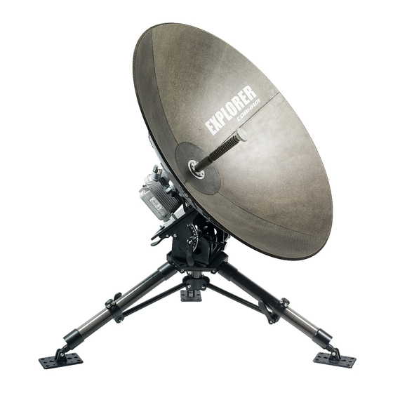
- Page 1 EXPLORER 3075GX Manual-Deploy Fly-Away System for Inmarsat GX User & installation manual...
- Page 2 Manuals issued by Thrane & Thrane A/S are periodically revised and updated. Anyone relying on this information should acquire the most current version e.g. from www.cobham.com/satcom, Cobham SYNC Partner Portal, or from the distributor.
-
Page 3: Safety Summary
Cobham SATCOM may perform service - failure to comply with this rule will void the warranty. Power supply The voltage range for the EXPLORER 3075GX is 100 – 240 VAC (nominal), 4 A, 50/60 Hz. Use the original power cable delivered with the equipment and make sure to apply safety ground to the terminal. - Page 4 with the power cable removed. To avoid injuries, always disconnect power and discharge circuits before touching them. WARNING! Be aware of pinch points while the antenna is being positioned, deployed or stowed. Failure to comply with the rules above will void the warranty! FCC §15.105: Information to the User NOTE: This equipment has been tested and found to comply with the limits for a Class B digital device, pursuant to part 15 of the FCC Rules.
-
Page 5: Table Of Contents
Intended readers .........................1-1 1.1.2 Software version ........................1-1 1.1.3 Typography ..........................1-1 Precautions ..........................1-2 Chapter 2 Introduction EXPLORER 3075GX Manual-Deploy Fly-Away System for Inmarsat GX 2.1.1 Overview ..........................2-1 2.1.2 Global Xpress (GX) service ....................2-2 2.1.3 Service activation ........................2-2 Description of the system components ............2-3 2.2.1... - Page 6 5.2.2 Software update procedure ...................5-9 Status signalling with LEDs and status messages ........ 5-12 5.3.1 LEDs on the keypad of the EXPLORER 3075GX ..........5-12 5.3.2 Status information of the modem ................5-13 To return units for repair ..................5-14...
-
Page 7: Chapter 1 About This Manual
1.1.1 Intended readers This is a user and installation manual for the EXPLORER 3075GX system, intended for users of the system and service personnel. It is important that you observe all safety requirements listed in the beginning of this manual, and install the system according to the guidelines in this manual. -
Page 8: Precautions
Some materials can be dangerous. CAUTION! Do not use materials that are not equivalent to materials specified by Cobham SATCOM. Materials that are not equivalent can cause damage to the equipment. Chapter 1: About this manual 98-144390-C... -
Page 9: Chapter 2 Introduction
2.1.1 Overview The EXPLORER 3075GX is a manual-deploy 75 cm fly-away antenna system, designed for operation in the Ka-band. The integrated GX modem, also known as the iDirect Core Module, facilitates the acquisition of an operational satellite based on the terminal's GPS location. -
Page 10: Global Xpress (Gx) Service
2.1.2 Global Xpress (GX) service The EXPLORER 3075GX is a unique GX antenna system operating in the K/Ka-band (19.2 to 30 GHz). It is used with the Global Xpress service from Inmarsat, delivering consistent high- performance download speeds of up to 50 Mbps and 5 Mbps over the uplink. The following figure shows the coverage map of the GX service. -
Page 11: Description Of The System Components
Description of the system components Description of the system components 2.2.1 Antenna positioner The manual-deploy antenna positioner can accommodate 0° to 90° of angular movement in the elevation axis and 27° of fine adjustment ° in the azimuth axis. The mechanical assemblies rely on two independent axes to allow for precise antenna pointing. -
Page 12: Rf Assembly
Description of the system components 2.2.2 RF assembly The RF assembly includes the BUC, LNB, reflector hub, filter/polarizer, and feed horn. It also contains a mounting bracket for mounting onto the tripod. Once the RF assembly is mounted, the quick-release locks beneath the positioner mounting plate hold the assembly securely in place. -
Page 13: Electronics Enclosure
The menus show how the system has been configured. The three LED light indicators are described in LEDs on the keypad of the EXPLORER 3075GX on page 5-12. You can see warnings, errors and information messages in the display. Signal strength is indicated on the display as 7 blocks. -
Page 14: Lan Ports And Wlan
• Three connectors (LAN2 to LAN4) for user PCs for Internet etc., configured by the GX modem. The EXPLORER 3075GX has a WLAN module. Access to one of the LAN ports using WLAN must be set up in the web interface, see To configure the LAN network on page 4-7. -
Page 15: Chapter 3 Assembly & Start Up
• To disassemble and pack the antenna What’s in the box 3.1.1 To unpack Two transit cases contain the EXPLORER 3075GX antenna system: • Case with RF assembly and electronics enclosure (left) • Case with tripod, antenna panels and cables (right) Figure 3-1: 2 transit cases... -
Page 16: Initial Inspection
To assemble the EXPLORER 3075GX The cases contain the following items: • Tripod and electronics enclosure • RF feed assembly • Transmit (Red, Tx) & Receive (Blue, Rx) RF cables • BUC power cable (Gray) • Power cable • Quick guide •... -
Page 17: Assembly
To be fully operational, you must deploy the tripod, install the RF assembly and the reflector, and connect the IFL and power cables. Then you can make a manual pointing to acquire the network. To assemble the EXPLORER 3075GX, do as follows: 1. Unpack the tripod, place it upon level ground. Bubble meter Figure 3-2: Electronics enclosure and support legs 2. - Page 18 To assemble the EXPLORER 3075GX Figure 3-4: To mount the RF assembly 5. Lift the two fastening screws and position the RF assembly on the top plate of the tripod. 6. Re-engage the screws to lock the RF assembly on the top plate.
- Page 19 To assemble the EXPLORER 3075GX 13.Connect the cables: (1) BUC power cable (Gray) to the MIL connector (2) Transmit (Red, Tx) cable IFL RG-6 to the BUC Transmit port (3) Receive (Blue, Rx) cable IFL RG-6 to the LNB Receive port.
-
Page 20: Power On And Manual Pointing
Power on and manual pointing Power on and manual pointing To bring the EXPLORER 3075GX into the network, you point the antenna toward the Global Xpress satellite and follow the signal-strength indications to peak on the signal. The manual pointing takes typically five minutes. - Page 21 Power on and manual pointing 5. On the manual point page, the terminal displays target elevation (ELE) and azimuth (AZI) angles. Point the antenna coarsely towards the satellite (azimuth within 27° of target) by turning the tripod. Make sure the tripod is level after movement. Use a compass to find the pointing direction.
-
Page 22: To Disassemble And Pack The Antenna
To disassemble and pack the antenna 12.Repeat steps 10 and 11 until the signal strength is at its maximum. 13.Tighten the quick-release locks for elevation. 14.At the peak of the signal press OK. This sends a command to the integrated GX modem to allow the transmission of data. -
Page 23: Chapter 4 Setup And Operation
Connection to the web interface To connect to the web interface do as follows: 1. Switch on the EXPLORER 3075GX system. Wait until the LEDs on the front plate show that the system is ready to be configured. • Power LED: Green •... - Page 24 Setup with the web interface for PC To access the web interface, do as follows: 1. On the ACU keypad, push and hold the left arrow key for 5 seconds. 2. Wait for the very short display of Local administration, followed by the event text: 0807F-0 WARNING Local administration enabled.
- Page 25 Figure 4-2: Web interface: DASHBOARD Acquisition process The EXPLORER 3075GX antenna must be manually pointed after power on. See Power on and manual pointing on page 3-6. The antenna is fully operational when the display of the electronics enclosure shows ACQUISITION OK and the field in the upper status line of the display shows MDM:NETOK.
- Page 26 Setup with the web interface for PC The DASHBOARD is the first screen that is displayed. It shows the properties and status of the EXPLORER 3075GX. Figure 4-4: Web interface: DASHBOARD The web interface has the following sections: 1. The navigation pane holds the main menu. Clicking an item in the menu opens a submenu in the navigation pane or a new page in the contents section.
- Page 27 GSC (GX) or Narrow band Tracking RF frequency Current RF tracking frequency ACU part name, Antenna Part names, serial numbers for antenna, software version of the part name, ACU serial EXPLORER 3075GX. number, Antenna serial number, Software version Table 4-2: Web interface: DASHBOARD 98-144390-C...
- Page 28 Table 4-3: Web interface, DASHBOARD, MODEM section Description BUC TX On or Off. Shows if the EXPLORER 3075GX has enabled the BUC or not. It is the same TX ON/TX OFF as shown in the display. Table 4-4: Web interface, DASHBOARD, TX section...
-
Page 29: To Configure The Lan Network
Important the Internet. It must be located behind a dedicated network security device such as a firewall. If any ports of the EXPLORER 3075GX are exposed to the Internet you must change the default passwords as anyone with access and malicious intent can render the EXPLORER 3075GX inoperable. - Page 30 Setup with the web interface for PC Sections Preferred use NETWORK The host name is used for identifying the EXPLORER 3075GX. The default Host host name is acu. You can change the name. Letters (a-z), digits (0-9) and name hyphen (-) are allowed as legal characters.
-
Page 31: Wlan Settings
Disabled: WLAN access point is hidden. 6. Type in the SSID of your choice or accept the default SSID, which is Cobham. The SSID is the name of the wireless local area network. It is a text with maximum 32 characters. -
Page 32: Navigation
• Manual pointing: This turns off the motors in the antenna and you must make a manual pointing using the hand crank. • Fixed installation: Selected this if the EXPLORER 3075GX is set up as a fixed installation, i.e. when the EXPLORER 3075GX will not move over time and where access to the EXPLORER 3075GX is not intended and/or difficult. -
Page 33: Administration
Administration settings require an Administration user name and password. To log on as administrator, do as follows: 1. Open your Internet browser and enter the IP address of the EXPLORER 3075GX: http://192.168.0.1. 2. Enter the Administration user name admin and admin password press and hold the left arrow key for 5 seconds and enter the user name admin. -
Page 34: User Permissions (Guest Login)
4.1.7 User permissions (guest login) You can manage user access to certain functions of the EXPLORER 3075GX system. You can allow or deny users that are not administrators (user name: guest, password: guest) access to certain functions and make these pages read-only. This is useful if you want to protect the system against unintended changes or tampering of the system. -
Page 35: Import And Export Of A System Configuration
VSAT modem profiles, LAN setup, user permissions etc. If you need to reuse a configuration in another EXPLORER 3075GX, you can save the current configuration to a file, which can then be loaded into another EXPLORER 3075GX. You can also use this feature for backup purposes. - Page 36 Figure 4-10: Web interface: Administration, Export/import configuration 2. Click the button Export. Follow the download instructions on the screen. You can use this configuration file for upload into another EXPLORER 3075GX, To load a configuration from a file, do as follows: 1.
-
Page 37: Reset To Factory Default
Important satellite and VSAT modem profiles, network setup, user permissions and ACU display brightness settings. When resetting EXPLORER 3075GX to factory default, the following settings are deleted or reset to factory default: • Navigation settings • All added satellite profiles •... - Page 38 Setup with the web interface for PC Reset to factory default - integrated GX modem CAUTION! Administrators only. Close this page for guest users, see User permissions (guest login) on page 4-12. WARNING! The system becomes inoperable if you select Level 3: Default Factory Configuration in the drop down list.
-
Page 39: Keypad And Display Menus
Signal strength Figure 4-13: Display and keypad of the ACU (example) 1. Current status of the EXPLORER 3075GX (examples): ANTENNA SOFTWARE UPLOAD ANTENNA POST (Power-On Self Test) READY (waiting for data from the modem or no satellite profile selected) -
Page 40: Navigating The Menus
Keypad and display menus 4.2.2 Navigating the menus Use the keypad to navigate the menus. • Use the arrow keys and to go through the menu items or enter a number, digit by digit. • Press OK or to select a menu item. •... - Page 41 Description MANUAL POINTING Shows current azimuth, elevation and signal strength. MAIN View with current status of the EXPLORER 3075GX. Example when logged on to the satellite: This view is displayed after a time out of 10 minutes. Press any key (except left arrow) to enter the menu at MAIN.
- Page 42 Keypad and display menus ANTENNA Description SERIAL NUMBERS Serial number of the EXPLORER 3075GX and an Inmarsat serial number. LOCAL ADMIN Shows that the terminal is set into local administration mode. Only user name admin is needed and the terminal is in admin mode for 1 hour.
-
Page 43: Brightness Of The Display
To access the mobile web interface, do as follows 1. Press the On/Off button to power up the EXPLORER 3075GX. 2. Connect your smartphone or tablet to the WLAN of the EXPLORER 3075GX. For details on WLAN setup. see WLAN settings on page 4-9. - Page 44 Web interface for tablet and smartphone Figure 4-15: Mobile web interface, logon page and status page To access the menu, tap the icon in the top right corner. The following menus are available: Description Status Shows the system status, host name, position, heading, selected satellite profile, modem etc.
-
Page 45: Chapter 5 Service
If this manual does not provide the remedies to solve your problem, contact your service provider. 5.1.1 Preventative maintenance The EXPLORER 3075GX is constructed to require a minimum amount of regular maintenance. WARNING! Potentially hot surface when the system is operated in hot environments without the possibility for ventilation. Contact may cause burn. -
Page 46: Help Desk And Diagnostics Report
5. Click Legal notice to display the licence text for the source code of the parts of the EXPLORER 3075GX software that fall under free and open source software. 6. In the section Download Reports click the button Download. The diagnostics report (txt file) is downloaded to your computer. -
Page 47: Self Test
System messages on page B-1. Self test You can start a self test of the EXPLORER 3075GX. The self test checks all vital parts of the unit. If a malfunction is detected, the unit provides system messages with a description of the failing test. -
Page 48: Power Cycle
General support 5.1.3 Power cycle To power-cycle the antenna do the following: 1. Press and hold and until the ACU display shuts down and the antenna reboots. Figure 5-2: To reset the system 2. Wait until the antenna has rebooted and is operational again. The last active satellite profile will be used. - Page 49 General support Each satellite profile has one assigned modem profile. Figure 5-4: Web interface: SETTINGS, Satellite profiles — new entry (example) To add or edit a satellite profile, do as follows: 1. Go to SETTINGS > Satellite profiles and click Edit or New entry. 2.
-
Page 50: Gx Modem: One Touch Commissioning (Otc)
General support 4. Click Apply to add the new profile to the list of VSAT modem profiles or to accept the edits. For a generic modem you enter all parameters in the satellite profile. Figure 5-6: Satellite profile with generic GX modem 5.1.5 GX Modem: One Touch Commissioning (OTC) You may have to make the One Touch Commissioning (OTC) for the modem. -
Page 51: Lnb Data Update
General support Figure 5-7: Web interface: SERVICE > Modem, Factory default 3. At Modem access click the link. 4. Type the user name admin (default) and the password iDirect (default). Figure 5-8: Unified web interface of the Core Module 5. In the menu Commissioning click One Touch Commissioning. 6. -
Page 52: Proxy Server Settings In Your Browser
General support 2. Enter the new values as shown on the label: LNB-LPN: LNB model number LNB-LSN: LNB serial number, in Inmarsat format L-MID: Manufacturer ID LNB-FID: LNB function ID (typically empty, shown with a "-") 3. Click Apply to save the new settings. 4. -
Page 53: Software Update
1. Power up the EXPLORER 3075GX system. 2. Connect a PC to LAN interface 1 (Service port, standard). 3. Open your Internet browser and enter the IP address of the EXPLORER 3075GX. The default IP address is http://192.168.0.1. 4. Type in the user name admin and the admin password press and hold the left arrow key for 5 seconds and enter the user name admin. -
Page 54: To Verify The Software Update
To verify the software update 1. The software version can be viewed in the DASHBOARD window of the web interface. 2. After completing the software update procedure, the EXPLORER 3075GX will perform a POST (Power On Self Test). 3. When the POST has finished, the green Pass/Fail LED on the keypad must become steadily green. - Page 55 Commissioning (OTC) on page 5-6 for information how to connect to the web interface of the GX modem. Software recovery (safe mode) If the EXPLORER 3075GX has become inoperative, a software recovery update may bring it back into an operational state. To make a software recovery, do as follows: 1.
-
Page 56: Status Signalling With Leds And Status Messages
Status signalling with LEDs and status messages Built-In Test Equipment The EXPLORER 3075GX has a Built-In Test Equipment (BITE) function in order to make fault diagnostics easy during service and installation. The BITE test is performed during: • Power On Self Test (POST), which is automatically performed each time the system is powered on. -
Page 57: Status Information Of The Modem
5.3.2 Status information of the modem The modem status is shown in the display of the EXPLORER 3075GX in the menu Modem (see The menu tree on page 4-18). The current status is communicated by a text string: Steady green, red or yellow, or flashing green, red or yellow: NET LED, STAT LED, TX LED, RX1 LED, RX2 LED, PWR LED, TEMP LED, FAN LED. -
Page 58: To Return Units For Repair
Your dealer, installer or Cobham SATCOM partner will assist you whether the need is user training, technical support, arranging on-site repair or sending the product for repair. Your dealer, installer or Cobham SATCOM partner will also take care of any warranty issue. -
Page 59: Appendix A Technical Specifications
Appendix A Technical specifications Specifications Ka-Band Receive Transmit Feed 2 Port Circular Frequency range (GHz) 19.2 - 20.2 29 - 30 Gain (dBi ± 0.2) 41.0 44.5 1.5 1.0 Axial ratio (dB) Polarization LHCP RHCP G/T - Comm @ 30° EL, Midband (dB/°K) 17.3 EIRP @ Midband (dBW) 51.5... - Page 60 Specifications Weights and measures Terminal 21.5 kg (47.5 lbs) Transport cases (2) Airline checkable Case with base unit and RF assembly Dimensions (L/W/D) 62.5/50/29.7 cm (24.6/19.7/11.7 in) Weight <23 kg (50.7 lbs) Case with reflector panels, tripod and cables Dimensions (L/W/D) 79.5/51.8/31 cm (31.3/20.4/12.2 in) Weight <23 kg (50.7 lbs)
-
Page 61: Appendix B System Messages
• CM (Continuous Monitoring) – automatically performed while the system is in operation. When the EXPLORER 3075GX detects an event that requires your action, it issues an event message and the red Fail/Pass LED in the LED panel of the ACU is lit. As long as an event is active, it is shown in the ACU display and in the web interface (in HELPDESK >... -
Page 62: List Of Events
List of events List of events Error code Severity Description Explanation (ID) 08065-0 ADM WARNING GNSS data Missing GPS data (fix). 08067-0 ADM ERROR PCB temperature ADM temperature too high. The ACU is not equipped with a fan, so make sure there is compliance with the environmental specifications. - Page 63 List of events Error code Severity Description Explanation (ID) 0810D-0 ADM ERROR Antenna communication Link to the ACU could not be established. Either the ACU is malfunctioning, or - if the system software has just been updated - the software is too old and is not compatible with the ACU hardware.
- Page 64 List of events Error code Severity Description Explanation (ID) 09000-0 KDM ERROR KDM 3V3 supply Internal 3V3 voltage supply error in the KDM. 09001-0 KDM ERROR KDM 12V supply Internal 12V voltage supply error in the KDM. 09002-0 KDM ERROR KDM display Display hardware error in the KDM.
-
Page 65: Appendix C Approvals
Appendix C Approvals This appendix lists the approvals for EXPLORER 3075GX. 98-144390-C... -
Page 66: Eu Declaration Of Conformity
Document no.: 99-157511-A Thrane & Thrane A/S trading as Cobham SATCOM. Registered no.: DK - 65 72 46 18. Registered address: Lundtoftegaardsvej 93 D, 2800 Kgs. Lyngby, Denmark This memo, which may contain confidential information, is intended solely for the use of the individual(s) or organisation to whom it is addressed. -
Page 67: Glossary
Glossary Glossary ADU Bus Slave ACU Digital Module. A main processor board in the ACU. Antenna Module Bus Block Up Converter. The BUC can be thought of the “transmitter”, and its actions are effectively the direct opposite to the LNB. The BUC consists of the Up Converter and HPA. Continuous Monitoring Digital Video Broadcasting, a set of standards relating to digital television. - Page 68 Glossary of protection; e.g. IPX4 which addresses moisture resistance only. Internet Protocol. The method or protocol by which data is sent from one computer to another on the Internet. Keyboard and Display Module of the ACU Local Area Network Light Emitting Diode Low Noise Blockdown Converter.
-
Page 69: Index
Index Index configuration , 4-13 copy access , 4-13 export , 4-12 limit , 4-13 import acquisition , 4-7 LAN network , 4-19 manual , 4-3 site map , 4-3 search pattern , 4-1 step-by-step activate satellite profile , 4-1 Configuration program , 4-22 with smartphone or tablet... - Page 70 Index , 4-10 , 4-12 fixed installation limit access to web interface , 4-10 fixed position , 5-7 exchange , 4-17 LO frequencies load GMU web interface , 4-13 configuration GX modem log off , 5-7 web interface , 4-12 administrator guest login...
- Page 71 Index permissions setup , 4-13 , 5-7 user new LNB , 5-12 , 4-12 Person Activated Self Test user permissions , 4-3 pointing site map , 4-19 manual smartphone , 4-21 position mobile web interface , 4-10 , 5-11 enter software recovery , 4-10 , 5-9...
- Page 72 Index web interface , 5-6 browser settings , 4-1 connect , 3-5 connection , 4-21 for smartphone or tablet , 4-2 login , 4-21 mobile , 5-7 modem , 4-4 navigating , 2-5 overview Wifi , 4-9 encryption key , 4-9 name wireless local area network , 4-9...
Need help?
Do you have a question about the EXPLORER 3075GX and is the answer not in the manual?
Questions and answers