
Related Manuals for Advantech WP-5530-PD10


Summary of Contents for Advantech WP-5530-PD10
- Page 1 WP-5530 Series Bezel Free All-in-One Modular Wall-Mount POS System User Manual Before installing and operating the unit, please read this user manual thoroughly and retain for reference. Ver 1.0_2015/01/05...
-
Page 2: How To Use This Manual
How to Use This Manual This manual contains information to set up and use the WP-5530. In addition, instructions are included for added hardware, software, upgrades, and optional items. Chapter 1 An introduction to what you find in the box and an overview of product specifications, appearance, and interface. -
Page 3: Federal Communications Commission (Fcc) Notice
Federal Communications Commission (FCC) Notice This equipment has been tested and found to comply with the limits for a Class A digital device, pursuant to Part 15 of the FCC Rules. These limits are designed to provide reasonable protection against harmful interference in a residential installation. -
Page 4: Copyright
Copyright The information in this guide is subject to change without prior notice. The manufacturer shall not be liable for technical or editorial errors or omissions contained herein, nor for incidental or consequential damages resulting from the furnishing, performance, or use of this material. This manual contains information protected by copyright. -
Page 5: Precautions
Precautions 1. Please read these safety instructions carefully. 2. Keep this User Manual for later reference. 3. Disconnect this equipment from the AC outlet before cleaning. Do not use liquid or spray detergent for cleaning. Use only a moistened sheet or cloth. 4. -
Page 6: Table Of Contents
Contents How to Use This Manual Federal Communications Commission (FCC) Notice Copyright Precautions Chapter 1 Introduction ....................1 Features ............................. 1 Specifications ............................1 Package Contents ..........................3 Base System ............................4 Expandable Main Display ........................4 Convertible Pole-Type 2nd Display (optional) ..................6 Dimensions ............................ - Page 7 TXE Driver Installation ........................39 Win8 BMI Driver Installation for IMB-151 .................... 40 ELO Touch Screen Driver Installation ....................41 Abon Touch Screen Driver Installation ....................43 TPK Touch Screen Driver Installation ....................45 Audio Driver Installation ........................46 Ethernet Driver Installation For IMB-151 ..................... 47 Ethernet Driver Installation For IMB-183 .....................
-
Page 8: Introduction
Device Option: MSR, RFID, iButton, Fingerprint or IC card reader RoHS compliant Specifications System Configuration WP-5530-PD10 WP-5530-PD20 Intel® Haswell Core i7 / i5 / i3 / Intel® BayTrail-D quad-core J1900 Pentium processor 2.0 GHz processor onboard with LGA1150 CPU socket ®... - Page 9 I/O Ports WP-5530-PD10 WP-5530-PD20 USB Ports 5 x External: 2 x USB 2.0, 2 x USB 3.0, 1 x 12V powered USB 3 x External: COM1,COM2,COM3 3 x External: COM1,COM2,COM3 Serial Ports (D-Sub 9-pin ; optional power with (D-Sub 9-pin ; 5V is default)
-
Page 10: Package Contents
Package Contents POS System AC Power Cord Utility and Main Wall Mount Board Chipset Swing Arm Kit Driver CD (optional) Options Magnetic Stripe Reader (MSR) Module: triple track 2-in-1 Module (Magnetic Stripe Reader + Fingerprint Reader) 2-in-1 Module (Magnetic Stripe Reader + I-Button Reader) ... -
Page 11: Base System
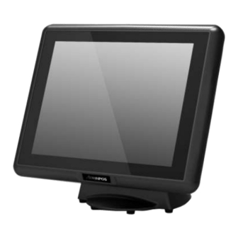
Base System Before you begin, take a few moments to become familiar with the WP-5530. 15” Bezel Free Touch Screen Base Rear Mount VFD... -
Page 12: Expandable Main Display
Expandable Main Display The four sides of the main display are specially designed for expandable functions and connect with one of the available internal USB ports or PS/2 for operation. Optimized for simple installation, these interfaces do not require any voltage setting adjustments. ... -
Page 13: Convertible Pole-Type 2Nd Display (Optional)
Convertible Pole-Type 2nd Display (optional) The pole-type 2nd display is for use with the POS system to display purchase prices and change amounts to customers. It is also capable of displaying advertising messages and announcements. Five types of pole mount display choices are available: a 10.1” LCD monitor, a 12” LCD monitor and a 15” LCD monitor. -
Page 14: Dimensions
Dimensions (Unit: mm) -
Page 15: Connector Panel
Connector Panel The WP-5530's primary connector panel is located at the rear. For WP-5530-XX10 12V/24V Cash Drawer Switch 12V Output 12V POWERED USB COM1/2/3 (RI/5V/12V) Line-Out 12V DC IN HDMI Cash Drawer 2 x USB2.0 2 x USB3.0 Mic-In For WP-5530-XX20 12V Output 12V POWERED USB 12V/24V Cash... -
Page 16: Standard Hardware And Upgrades
Chapter 2 Standard Hardware and Upgrades Precautions Before performing hardware changes, be sure to carefully read all of the applicable instructions, cautions, and warnings in this guide. WARNING! To reduce the risk of personal injury from electrical shock, hot surfaces, or fire: Disconnect the power cord from the wall outlet and allow the internal system components to cool before touching. -
Page 17: Opening System Box
Opening System Box CAUTION: To prevent loss of work and damage to the system or drive: If you are inserting or removing a drive, shut down the operating system properly, turn off the system, and unplug the power cord. Do not remove a drive while the system is on or in standby mode. - Page 18 5. Unscrew six screws on the back cover of main LCD display as shown below to remove it. 6. Unscrew a screw on the HDD tray as shown below to remove it.
-
Page 19: Clearing Cmos
Clearing CMOS The WP-5530's configuration (CMOS) may occasionally be corrupted. If it is, it will be necessary to clear the CMOS memory using jumper CLRCMOS1. Please refer to Chapter 4 for the exact CLRCMOS1 pin positions. 1. Turn off the system power properly through the operating system, then turn off any external devices. -
Page 20: Memory Installation
Memory Installation The memory sockets on the main board can be populated with up to an industry-standard DIMM. The WP-5530 comes standard with one preinstalled DIMM. To achieve maximum memory performance, up to 8GB of memory for IMB-151 or up to 16GB of memory for IMB-183can be added. CAUTION: You must disconnect the power cord and wait approximately 30 seconds for the power to drain before adding or removing memory cards. - Page 21 4. Detach the right side cover, left side cover and rear cover. 5. Unscrew six screws on the back cover of main LCD display as shown below to remove it. 6. Unscrew a thumb screw on the HDD tray as shown below to remove it. 7.
- Page 22 8. Insert the new or replacement memory card into the socket, almost covering the gold contacts completely, then push the card down. If the card is fully inserted and properly seated, the metal latches will be in the closed position indicated. 9.
-
Page 23: Removing And Replacing The Sata Hard Disk
Removing and Replacing the SATA Hard Disk NOTE: This system does not support Parallel ATA (PATA) hard drives. Before removing the original hard drive, be sure to back up its data so that you can transfer the data to the replacement hard drive. Also, if you are replacing the primary hard drive, make sure you have a recovery disc set to restore the operating system, software drivers, and any software applications that were preinstalled on the system. - Page 24 4. Unscrew a screw on the HDD tray as shown below to remove it. 5. Slide the HDD box off the main system. 6. Unscrew two screws on the HDD tray as shown below to remove it. Next, insert the replacement hard disk into the HDD tray.
-
Page 25: Chapter 3 Optional Components And Peripherals
Chapter 3 Optional Components and Peripherals MSR/Fingerprint/I-Button/IC Card Module Installation NOTE: The MSR module can only be installed to its designated position and socket; the same with the wireless module. Their locations are not interchangeable. 1. Turn off the system power properly through the operating system, then turn off any external devices. - Page 26 6. Reconnect the power cord and any external devices, then turn on the system. NOTE: The MSR module configuration tool is in the included CD. If you need configure MSR module, please execute the utility according to the procedure specified in Chapter 5.
-
Page 27: Rear Mount Vfd Installation
Rear Mount VFD Installation 1. Turn off the system power properly through the operating system, then turn off any external devices. 2. Disconnect the power cord from the power outlet and disconnect any external devices. CAUTION: Regardless of the power-on state, voltage is always present on the main board as long as the system is plugged into an active AC outlet. -
Page 28: Cash Drawer Installation
Cash Drawer Installation NOTE: Before connecting cash drawer to the system, please make sure the driver voltage and cable pin assignment of the cash drawer matches the definition of the system's cash drawer port. Before installing the cash drawer to the system, please make sure the system driver has been installed. -
Page 29: Chapter 4 Main Board Configuration
Chapter 4 Main Board Configuration Jumper and Connector Locations of IMB-151... - Page 30 Connector Allocations Connector Function ATX Power Connector 2-pin UPS Module Power Input Connector 4-Pin CPU FAN Connector 4//5/6 PWR_COM6 / PWR_COM4 / PWR_COM3 Jumper Internal COM Port Headers Printer Port Header PWR_COM1 Jumper Digital Input / Output Pin Header PWR_COM2 Jumper Digital Input / Output Power Select TPM Header Chassis Intrusion Headers...
-
Page 31: Jumper Settings Of Imb-151
Jumper Settings of IMB-151 To set jumper positions, place the jumper shunt over the pins designated in the table (SHORT) or remove (NC) it from the jumper pins and store for future use. Default settings are indicated with a star symbol (). ATX12V1 ATX Power Connector (Input 9V-19V) PIN No. - Page 32 Chassis Intrusion Headers PIN No. Function Open Active case open Short Normal MSATA_SEL1 mSATA Select PIN No. Function 1-2 Short SATA2_2 + mini-PCIe 2-3 Short mSATA, SATA2_2 no function CLRCOMS1 Clear CMOS Header PIN No. Function 1-2 Short Normal ...
- Page 33 BLT_PWM1 Backlight Control Level PIN No. Function 1-2 Short 2-3 Short +5V...
-
Page 34: Jumper And Connector Locations Of Imb-183
Jumper and Connector Locations of IMB-183... - Page 35 Connector Allocations Connector Function 2-pin UPS Module Power Input Connector (UPS_IN1) PS2 Keyboard/Mouse Header 4-pin ATX Power Input/Output Connector USB2.0 Headers (USB4_5, USB8_9) SATA3 Connectors (SATA3_1, SATA3_2) Digital Input / Output Pin Header SATA Power Output Connector (SATA_PWR1) VCCM Power Selection Digital Input / Output Power Selection 10/11/12/13 COM1, 2, 3, 4 Headers (COM1/2/3/4)
-
Page 36: Jumper Settings Of Imb-183
Jumper Settings of IMB-183 To set jumper positions, place the jumper shunt over the pins designated in the table (SHORT) or remove (NC) it from the jumper pins and store for future use. Default settings are indicated with a star symbol (). VCCM_PWR1 VCCM Power Selection PIN No. - Page 37 CLRCOMS1 Clear CMOS Header PIN No. Function 1-2 Short Normal 2-3 Short Clear CMOS Chassis Intrusion Headers PIN No. Function Open Single Short Chassis Intrusion Headers PIN No. Function Open Single Short GND...
-
Page 38: Chapter 5 Software Setup
Chapter 5 Software Setup Pre-Installation Requirements This system comes with a variety of drivers for different operating systems. A software CD is included in the package contents. The following section documents the procedures used to install the peripheral. 1. Insert sofeware CD into a system. 2. - Page 39 elect your POS model Number. 6. Select the peripheral driver that you want to install and then follow on-screen instructions to install your driver or refer to following procedures specifying how every driver is to be installed.
-
Page 40: Intel Chipset Driver Installation
Intel Chipset Driver Installation Click the Next button on the Welcome Click Yes on the License Agreement screen. screen. Click Next on the Information screen. Click Next to continue. Select one of the options and click Finish. -
Page 41: Intel Graphics Driver Installation For Imb-151
Intel Graphics Driver Installation for IMB-151 1. Click Next on the Welcome screen. 2. Click Yes on the License Agreement screen. Click Next on the readme File Information 4. Click Install. screen. Click Install. 6. Click Next. - Page 42 Select one of the options and click Finish.
-
Page 43: Intel Graphics Driver Installation For Imb-183
Intel Graphics Driver Installation for IMB-183 1. Click Next on the Welcome screen. 2. Click Yes on the License Agreement screen. Click Next on the readme File Information 4. Click Next. screen. Select one of the options and click Finish. -
Page 44: Smart Connect Driver Installation For Imb-183
Smart Connect Driver Installation For IMB-183 1. Click Next on the Welcome screen. 2. Click Next on the License Agreement screen. Click OK. 4. Click Next. Click Install to begin the installation. 6. Click the Finish to exit the Setup Wizard. -
Page 45: Management Engine Driver Installation For Imb-183
Management Engine Driver Installation For IMB-183 1. Click Next on the Welcome screen. 2. Click Yes on the License Agreement screen. Click Next. 4. Select one of the options and click Finish.. -
Page 46: Txe Driver Installation
TXE Driver Installation 1. Click Next on the Welcome screen. 2. Click Next on the License Agreement screen. Click Next on the Information screen. Click Install to install device software. Click Finish. -
Page 47: Win8 Bmi Driver Installation For Imb-151
Win8 BMI Driver Installation for IMB-151 1. Click Next on the Welcome screen. 2. Click Yes on the License Agreement screen. Click Next to continue. Select one option and click Finish. -
Page 48: Elo Touch Screen Driver Installation
ELO Touch Screen Driver Installation 2. Click Unzip on the WinZip Self-Extractor 1. Click OK on the Welcome screen. screen. Select language, click Next. 4. Click Next on welcome screen. 6. Select Auto-detect Elo Touchscreens, click Click Yes on the License Agreement screen. Next. - Page 49 Select COM3, click Next. 8. Click Next to confirm COM port selection. Click Finish.
-
Page 50: Abon Touch Screen Driver Installation
Abon Touch Screen Driver Installation 1. Click Next on the Welcome screen. 2. Select the hid report mode, then click Next. Check this option and click Next. 4. Check this option and click Next. Select destination Location and then click 6. - Page 51 Click Install to continue with the installlation. 8. Click Install to install this device software. Click Yes to restart the computer now.
-
Page 52: Tpk Touch Screen Driver Installation
TPK Touch Screen Driver Installation 1. Click Next on the Welcome screen. 2. Select a destination folder, then click Next. 3. Check Finish. -
Page 53: Audio Driver Installation
Audio Driver Installation 2. Select one of the options and click OK to finish 1. Click Yes on the Welcome screen. setup. -
Page 54: Ethernet Driver Installation For Imb-151
Ethernet Driver Installation For IMB-151 1. Click Next on the Welcome screen. 2. Click Install to begin the installation. 3. Click Finish. -
Page 55: Ethernet Driver Installation For Imb-183
Ethernet Driver Installation For IMB-183 2. Select one of the options and click Next on the 1. Click Next on the Welcome screen. Agreement screen. 3. Click Next. 4. Click Install to begin installation. 5. Click Finish. -
Page 56: Usb3.0 Driver Installation
USB3.0 Driver Installation 1. Click Next on the Welcome screen. 2. Click Yes on the Agreement screen. 3. Click Next. 4. Click Next. 5. Select one of the options and Click Finish. -
Page 57: Cir Device Driver Installation For Imb-151
CIR Device Driver Installation for IMB-151 1. Choose Setup Language and click Next. 2. Click Next on the Welcome screen. 3. Click Finish. -
Page 58: Rear Mount Vfd Usb-To-Serial Driver Installation (Optional)
Rear Mount VFD USB-to-Serial Driver Installation (optional) The WP-5530 VFD port is a USB interface. The 9mm VFD uses a Serial interface, so in order to enable it, you must install the included USB-to-Serial interface driver. 1. First, plug in the VFD Module. 2. -
Page 59: Rfid Driver Installation (Optional)
RFID Driver Installation (optional) 1. First, plug in the RFID Module. 2. Driver Path. X:\Peripheral\RFID\Windows 7_32Bit XP driver X:\Peripheral\RFID\Windows7_64Bit Driver 3. Device Manager (Install USB Serial converter) 4. Update device software. 5. Select driver path. 6. Driver installation has successful. Click Close. - Page 60 7. Fullfill Device Manager. 8. Install USB Serial Port. 9. Update Device Software. 10. Select Driver Path.
- Page 61 11. Driver installation has successful. Click Close. 12. Update Device Software.
-
Page 62: Msr Driver Installation (Optional)
MSR Driver Installation (optional) 1. Plug in MSR module. 2. Select your MSR interface PS2 or USB. 3. For PS2 interface: Run the MSRfgSetup_V1_4R7_PSW00025.exe. For USB interface: Enter the Software folder and then run the HISD_MSR_PSW00003.exe. 4. Follow on-screen instructions to install your MSR driver. NOTE: MSR with PS2 interface don’t support 64 Bits OS. -
Page 63: Fingerprint Reader Driver Installation (Optional)
Fingerprint Reader Driver Installation (optional) 1. Plug in the 2-in-1 Fingerprint Reader and MSR module. 2. Enter the SDK folder and then run the setup.exe. 3. Click Next on the Welcome screen. 4. Click Next on the License Agreement screen. 5. - Page 64 9. Wait as the driver is installed. 10. Click Finish. 11. Click Yes to restart the system (required).
-
Page 65: Ic Card Reader Driver Installation (Optional)
IC Card Reader Driver Installation (optional) 1. Plug in the 3-in-1 MSR/I-Button/IC Card Reader module. 2. Enter the EZ100PU Driver folder. 3. Select your POS operating system and then run the setup.exe. 4. Select language, click OK. 5. Click Next on the Welcome screen. 6. -
Page 66: System Driver Installation
System Driver Installation 1. Click Next on the Welcome screen. 2. Click Install on the Ready to Install screen. 3. Click Finish on the Completing installation screen. A system restart is required to complete the installation. -
Page 67: Opos Cco Driver Installation
OPOS CCO Driver Installation The OPOS driver for the WP-5530 supports the MSR, I-Button (KeyLock), RFID, VFD (Line-Display) and Scanner. Before installing the OPOS driver, please make sure the System Driver has been installed. 1. Click Next on the Welcome screen. 2. - Page 68 7. Click Finish on the Installation Complete screen.
-
Page 69: Opos Driver Installation
OPOS Driver Installation 1. Click Next on the Welcome screen. 2. Click Install on the Setup screen. 3. Click Finish on the Completing installation screen. -
Page 70: Appendix A. Sample C++ Cash Drawer Code For Windows
Appendix A. Sample C++ Cash Drawer Code for Windows NOTE: Requires installation of System Driver. Refer to the System Driver Installation section for instructions. //1. Open Cash Drawer // IOCTL Codes #define GPD_TYPE 40000 #define ADV_OPEN_CTL_CODE CTL_CODE(GPD_TYPE, 0x900, METHOD_BUFFERED, FILE_ANY_ACCESS) #define ADV_STATUS_CTL_CODE CTL_CODE(GPD_TYPE, 0x901, METHOD_BUFFERED,... - Page 71 bRet = DeviceIoControl(hFile, ADV_STATUS_CTL_CODE, NULL, 0, &ReadByte, sizeof(ReadByte), &ulBytesReturned, NULL); (bRet == FALSE || ulBytesReturned != 1) AfxMessageBox("Failed to Read from cash drawer driver"); CloseHandle(hFile); return; else AfxMessageBox(ReadByte ? “Drawer Open”: “Drawer Closed”); CloseHandle(hFile);...
-
Page 72: Appendix B. Sample Vb.net Cash Drawer Code For Windows
Appendix B. Sample VB.NET Cash Drawer Code for Windows NOTE: Requires installation of System Driver. Refer to the System Driver Installation section for instructions. Private Declare Function CreateFile "kernel32" Alias "CreateFileA" (ByVal lpFileName String, ByVal dwDesiredAccess Integer, ByVal dwShareMode Integer, ByVal lpSecurityAttributes IntPtr,... - Page 73 (iRet = 0 iBytesRtn <> 1) Then MsgBox("Error opening ADVSYS.sys. Error = " & Err.LastDllError) End If End Sub Private Sub Timer1_Tick(ByVal sender System.Object, ByVal System.EventArgs) Handles Timer1.Tick iBytesRtn As Integer iRet Integer, iStatus As Integer ' Get Drawer Status iRet = DeviceIoControl(DeviceHandle, ADV_STATUS_CTL_CODE, 0, 0, iStatus, 4, iBytesRtn, 0) (iRet = 0 iBytesRtn <>...
-
Page 74: Appendix C. Sample Vb6.0 Cash Drawer Code For Windows
Appendix C. Sample VB6.0 Cash Drawer Code for Windows NOTE: Requires installation of System Driver. Refer to the System Driver Installation section for instructions. Option Explicit On Private Declare Function CreateFile "kernel32" Alias "CreateFileA" (ByVal lpFileName String, ByVal dwDesiredAccess Long, ByVal dwShareMode Long,... - Page 75 Private Sub Form_Load() '-1673527296 Come from c code (40000 <<16) ADV_OPEN_CTL_CODE = CTL_CODE(-1673527296, &H900, METHOD_BUFFERED, FILE_ANY_ACCESS) ADV_STATUS_CTL_CODE = CTL_CODE(-1673527296, &H901, METHOD_BUFFERED, FILE_ANY_ACCESS) DeviceHandle = CreateFile("\\.\ADVSYS", GENERIC_READ GENERIC_WRITE, FILE_SHARE_READ FILE_SHARE_WRITE, SA, OPEN_EXISTING, FILE_ATTRIBUTE_NORMAL, 0) DeviceHandle = INVALID_HANDLE_VALUE Then 'Failed to Open Cash Drawer Driver MsgBox("Error opening ADVSYS.sys.
-
Page 76: Appendix D. Watch Dog C++ Sample Code For Imb-183
Appendix D. Watch Dog C++ Sample Code for IMB-183 //1. Open Cash Drawer // IOCTL Codes #define GPD_TYPE 40000 #define ADV_WDOGSec_CTL_CODE CTL_CODE(ADVPORT_TYPE, 0x902, METHOD_BUFFERED, FILE_ANY_ACCESS) #define ADV_WDOGMin_CTL_CODE CTL_CODE(ADVPORT_TYPE, 0x903, METHOD_BUFFERED, FILE_ANY_ACCESS) #define ADV_COLSE_CTL_CODE CTL_CODE(ADVPORT_TYPE, 0x904, METHOD_BUFFERED, FILE_ANY_ACCESS) 2. //Open Second Mode void OpenWDOG(UCHAR uWhichdog) // uWhichdog ... - Page 77 FILE_SHARE_WRITE, NULL,OPEN_EXISTING, FILE_ATTRIBUTE_NORMAL, 0); (m_hFile == INVALID_HANDLE_VALUE) AfxMessageBox("Unable to open Watch Dog Driver!"); return; // Close Watch Dog bRet = DeviceIoControl(hFile, ADV_COLSE_CTL_CODE CTL_CODE, &uTime, sizeof(uTime), NULL, 0, &ulBytesReturned, NULL); (bRet == FALSE || ulBytesReturned != 1) AfxMessageBox("Failed to write to Watch Dog driver");...
-
Page 78: Appendix E. Watch Dog Vb.net Sample Code For Imb-183
Appendix E. Watch Dog VB.NET Sample Code for IMB-183 Public Class Form1 Private Declare Function CreateFile "kernel32" Alias "CreateFileA" (ByVal lpFileName String, ByVal dwDesiredAccess Integer, ByVal dwShareMode Integer, ByVal lpSecurityAttributes IntPtr, ByVal dwCreationDisposition Integer, ByVal dwFlagsAndAttributes Integer, ByVal hTemplateFile IntPtr) As Integer Private Declare Function DeviceIoControl... - Page 79 End Sub Private Sub Button3_Click(ByVal sender System.Object, ByVal System.EventArgs) Handles Button3.Click 'Close Watch Dog iDrawer = &H0 iRet = DeviceIoControl(DeviceHandle, ADV_COLSE_CTL_CODE, iDrawer, 4, 0, 0, iBytesRtn, 0) (iRet = 0 iBytesRtn <> 1) Then MsgBox("Error opening ADVSYS.sys. Error = " &...
-
Page 80: Appendix F. Watch Dog Vb6 Sample Code For Imb-183
Appendix F. Watch Dog VB6 Sample Code for IMB-183 Option Explicit On Private Declare Function CreateFile "kernel32" Alias "CreateFileA" (ByVal lpFileName String, ByVal dwDesiredAccess Long, ByVal dwShareMode Long, ByVal lpSecurityAttributes SECURITY_ATTRIBUTES, ByVal dwCreationDisposition Long, ByVal dwFlagsAndAttributes Long, ByVal hTemplateFile Long) As Long Private Declare Function DeviceIoControl... - Page 81 'Open Second Mode iDrawer = Val(Text1.Text) 'Number of seconds 1 to 255 iRet = DeviceIoControl(DeviceHandle, ADV_WDOGSec_CTL_CODE, iDrawer, 4, 0, 0, iBytesRtn, SA1) (iRet = 0 iBytesRtn <> 1) Then MsgBox("Error opening WDOG.sys. Error = " & Err.LastDllError) End If Timer1.Enabled = True End Sub Private Sub...
Need help?
Do you have a question about the WP-5530-PD10 and is the answer not in the manual?
Questions and answers