Table of Contents
Advertisement
Quick Links
Advertisement
Table of Contents

Related Manuals for Advantech POC-S199 Series


Summary of Contents for Advantech POC-S199 Series
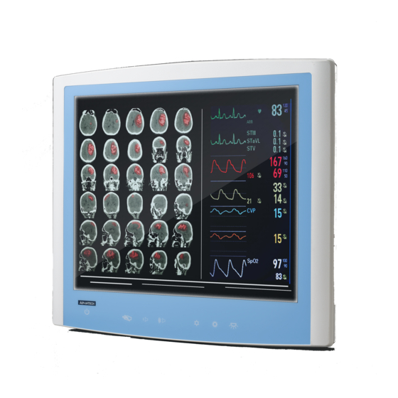
- Page 1 User Manual POC-S199 Series 19" Slim Point-of-Care Terminals with True Flat Panel...
- Page 2 Repair of the device may also only be carried out by trained service personnel. Advantech recommends that a service contract be obtained with Advantech Service and that all repairs also be carried out by them. Otherwise the correct functioning of the device may be compromised.
- Page 3 Caution! Do not replace battery yourself. Please contact a qualified technician or your local Advantech sales office. The computer is provided with a battery-powered real-time clock circuit. There is a danger of explosion if battery is incorrectly replaced. Replace only with same or equivalent type recommended by the manufacture.
- Page 4 Caution! When servicing the device, always use replacement parts that are quali- fied to Advantech standards. Advantech Medical cannot warrant or endorse the safe performance of third-party replacement parts for use with our medical device.
- Page 5 Warning! To avoid risk of electric shock, this equipment must only be connected to a supply mains with protective earth. Caution! This adapter Sinpro HPU101-107 is a forming part of the medical device. Remove the power cord to fully turn off the device. POC-S199 Series User Manual...
- Page 6 ISO 7000-1641 : Follow operating instructions or consult instructions for use. IEC 60417 -5009 : STAND-BY. IEC 60417-5032 : Alternating Current IEC 60417-5031 : Direct Current IEC 60417-5021 : Equipotentiality. ISO 7010-M002: Follow instructions for use. POC-S199 Series User Manual...
- Page 7 Consult the dealer or an experienced radio/TV technician for help Warning! Any changes or modifications made to the equipment which are not expressly approved by the relevant standards authority could void your authority to operate the equipment. POC-S199 Series User Manual...
- Page 8 Otherwise the correct functioning of the device may be compromised. Additional Information and Assistance Contact your distributor, sales representative, or Advantech's customer service cen- ter for technical support if you need additional assistance. Please have the following information ready before you call: ...
-
Page 9: Table Of Contents
Introduction ....................2 Specifications .................... 2 Dimensions ....................4 Figure 1.1 Dimensions of the POC-S199 series......4 Figure 1.2 VESA Mounting of the POC-S199 series ....4 Figure 1.3 POC-S199 series Front Panel ........5 1.3.1 Optional modules ................5 1.3.2... - Page 10 POC-S199 Series User Manual...
-
Page 11: Chapter 1 General Information
Chapter General Information... -
Page 12: Introduction
LED life time 70,000 Hours Contrast Ratio 1000:1 Response time / 10ms / 170(H) & 160(H) Viewing angle Mini PCIe (mSATA) 2 (Mini PCIe: 1 full-size,1half-size) Expansion Slot 1 x PCIe (x4) slot PCIe (Max. card length: 167.65mm) POC-S199 Series User Manual... - Page 13 700-1013 hPa (Operation) Pressure 700-1013 hPa (Storage/Transportation) Dimensions 470.5 x 415.2 x 75.64 mm (W x H x D) (18.52" x 16.35" x 2.98") Physical Characteristics Weight 7.4 kg (16.31 lb) VESA Mount 100x100 mm, 75x75 mm POC-S199 Series User Manual...
-
Page 14: Dimensions
Figure 1.1 Dimensions of the POC-S199 series VESA Mounting: 75 x 75 mm; 100x100 mm Please use M4x12L (Maximum) screw. Figure 1.2 VESA Mounting of the POC-S199 series Warning! Use suitable mounting apparatus to avoid risk of injury. POC-S199 Series User Manual... -
Page 15: Optional Modules
Figure 1.3 POC-S199 series Front Panel 1.3.1 Optional modules Memory: Up to 32GB DDR4 x 2 2.5" SATA HDD(65 degree)/SSD, mini-PCIe, PCIe X4 Touchscreen: Projected Capacitive PCIe Card: Dual LAN, Firewire, RS-232 1.3.2 Cleaning and Disinfecting During normal use of the POC (Point-of-Care Terminal) the device may become dirty and should be regularly cleaned. -
Page 16: Operating Principle
One arm / hand system capable of guiding and holding device – Average degree of aging-related short term memory impairment – impaired by 40 % resulting in 60 % of normal hearing at 500 Hz to 2 kHz POC-S199 Series User Manual... -
Page 17: Chapter 2 System Setup
Chapter System Setup... -
Page 18: A Quick Tour Of The Poc-S199 Series
A Quick Tour of the POC-S199 Series Before you start to set up the POC-S199 series, take a moment to become familiar with the locations and purposes of the controls, drives, connections and ports, which are illustrated in the figures below. -
Page 19: Rear View
I/O section is at the bottom of the panel PC, as shown in Figure 2.2. Figure 2.3. shows the I/O section including various I/O ports, serial ports, VGA port, the Ethernet port, and USB ports. Figure 2.2 Rear view of the Point of Care Terminal POC-S199 Series User Manual... -
Page 20: Figure 2.3 Rear View Of Multi I/O Ports
Figure 2.3 Rear view of Multi I/O ports Rear View: DC-IN USB2.0 X2 USB3.0 X2 DISPLAYPORT X1 GigaLAN X2 HDMI X1 RS-232/422/485 X2 Note! Equipotential terminal needs linking to the hospital ground/earth system before the system boots to protect operator and system. POC-S199 Series User Manual... -
Page 21: Installation Procedures
Installation Procedures 2.2.1 Connecting the Power Cord The POC-S199 series can only be powered by AC in. Be sure to always handle the power cords by holding the plug ends only. Follow these procedures in order: Connect the female end of the power cord to the system. -
Page 22: Connecting The Ground Pin
Step 3. Grounding cable plug with POC-S199 series Equipotential Terminal Running the BIOS Setup Program Your POC-S199 series was probably set up and configured by your dealer prior to delivery. You may still find it necessary to use the BIOS (Basic Input-Output System) setup program to change system configuration information, such as the current date and time or your type of hard drive. -
Page 23: Installing The Drivers
Power LED ON but no DC power output AC power is on and all switches ON, but system doesn't power on Contact your distributor, sales representative, or Advantech's customer service cen- ter for technical support if you need additional assistance. Please have the following information ready before you call: ... - Page 24 Guidance and Manufacturer's Declaration - Electromagnetic Emissions The model POC-S199 series is intended for use in an electromagnetic environment as spec- ified below. The customer or the user of the POC-S199 series should assure that it is used in such an environment.
- Page 25 Guidance and Manufacturer's Declaration - Electromagnetic Immunity POC-S199 series is intended for use in the electromagnetic environment specified below. The customer or the user of the model POC-S199 series should assure that it is used in such an environment. Electromagnetic...
- Page 26 Guidance and Manufacturer's Declaration - Electromagnetic Immunity The model POC-S199 series is intended for use in the electromagnetic environment speci- fied below. The customer or the user of the model POC-S199 series should assure that it is used in such an environment.
- Page 27 RF transmitters, an electromagnetic site survey should be considered. If the measured field strength in the location in which the POC-S199 series is used exceeds the applicable RF compliance level above, the POC-S199 series should be observed to verify normal operation. If abnormal perfor- mance is observed, additional measures may be necessary, such as reorienting or relocating the unit.
- Page 28 POC-S199 Series User Manual...
-
Page 29: Chapter 3 Operation And Safety
Chapter Operation and Safety... -
Page 30: General Safety Guide
Thermal The vent hole of the POC-S199 series rear cover functions as a cooling air flow inlet and outlet. These air inlets and outlets transfer heat from inside the computer to the cooler air outside. Do not block these holes/vents with any soft material. -
Page 31: Disconnect The Power
Never place anything on system case before turning off the computer. Never turn on your computer unless all of its internal and external parts are in place. Operating the computer when it is open or missing parts can be danger- ous and can damage your computer. POC-S199 Series User Manual... - Page 32 POC-S199 Series User Manual...
-
Page 33: Appendix A Install Vesa Mounting
Appendix Install VESA Mounting... -
Page 34: Install Vesa Mounting
PC into their system. Never use mounting brackets except as provided by Advantech to prevent unreliable mounting of the POC-S199 series. VESA mount installation should be carried out by a professional technician; please contact a service technician or your retailer if you need this service. - Page 35 POC-S199 Series User Manual...
- Page 36 No part of this publication may be reproduced in any form or by any means, electronic, photocopying, recording or otherwise, without prior written permis- sion of the publisher. All brand and product names are trademarks or registered trademarks of their respective companies. © Advantech Co., Ltd. 2020...
Need help?
Do you have a question about the POC-S199 Series and is the answer not in the manual?
Questions and answers