
Related Manuals for Advantech POC-S198


Summary of Contents for Advantech POC-S198
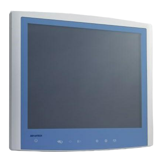
- Page 1 User Manual POC-S198 19" Slim Point-of-Care Termminal with True Flat Panel and IP54 Enclosure...
- Page 2 Repair of the device may only be carried out by trained service personnel. Advantech recommends that a service contract be obtained with Advantech Service and that all repairs also be carried out by them. Otherwise the correct functioning of the device may be compromised.
- Page 3 Discard used batteries according to the manufacturer’s instructions. Caution! The battery charging indicator is not included with this device. It will be added to the finished system assembly and be shown with the com- pleted system. POC-S198 User Manual...
- Page 4 Caution! When servicing the device, always use replacement parts that are quali- fied to Advantech standards. Advantech Digital Healthcare cannot war- rant or endorse the safe performance of third-party replacement parts for use with our medical device.
- Page 5 IEC 60878 and ISO 3864-B.3.6 : Warning: dangerous voltage ISO 7000-0434 : Caution, consult ACCOMPANYING DOCUMENTS. ISO 7000-1641 : Follow operating instructions or consult instructions for use. IEC 60417 -5009 : STAND-BY. IEC 60417-5031 : Direct current. IEC 60417-5021 : Equipotentiality. POC-S198 User Manual...
- Page 6 Consult the dealer or an experienced radio/TV technician for help Warning! Any changes or modifications made to the equipment which are not expressly approved by the relevant standard’s authority could void your authority to operate the equipment. POC-S198 User Manual...
- Page 7 Otherwise the correct functioning of the device may be compromised. Additional Information and Assistance Contact your distributor, sales representative, or Advantech's customer service cen- ter for technical support if you need additional assistance. Please have the following information ready before you call: ...
- Page 8 POC-W211 User Manual...
-
Page 9: Table Of Contents
Introduction ....................2 Specifications .................... 2 Dimensions ....................4 Figure 1.1 Dimensions of the POC-S198 ........4 Figure 1.2 VESA Mounting of the POC-S198 ......4 Figure 1.3 POC-S198 Front Panel..........5 Figure 1.4 POC-S198 Back I/O ..........5 1.3.1 Optional Modules ................ - Page 10 Front Bezel Button......39 Introduction ..................... 40 8.1.1 Front Button Map ................ 40 Chapter POC-S198 Advanced BIOS Function Introduction ..................... 42 Appendix A POC-S198 VESA Mounting....45 Install VESA Mounting ................46 Figure A.1 VESA Mounting 75x75mm, 100x100 mm ....46...
-
Page 11: General Information
Chapter General Information... -
Page 12: Introduction
The POC-S198 is specially designed to resist spills and water damage, and ensures dust resistance with its protected LCD and sealed ports. The POC-S198 is a reliable solution to your application's processing requirements. - Page 13 10 ~ 95% @ 40° C (Non-condensing) Humidity Shock Resistance 20 G peak acceleration (11 ms duration) Dimensions 470.5 x 415.2 x 102.2 mm (18.52" x 16.35" x Physical (W x H x D) 4.02") Characteristics Weight 7.5 Kg (16.5 lb) POC-S198 User Manual...
-
Page 14: Dimensions
Dimensions: 550 x 370 x 65 mm (Unit: mm) Figure 1.1 Dimensions of the POC-S198 VESA Mounting: 75 x 75 mm; 100 x 100 mm Figure 1.2 VESA Mounting of the POC-S198 Warning! Use suitable mounting apparatus to avoid risk of injury. POC-S198 User Manual... - Page 15 Figure 1.3 POC-S198 Front Panel Power Touchscreen Status Control Volume Down/Up Touchscreen Status Control Read Light Control Figure 1.4 POC-S198 Back I/O DC-IN USB 2.0 x4 DVI-Ix1 GigaLAN x2 RS-232 x1 232/422/485 POC-S198 User Manual...
- Page 16 DC-IN Figure 1.5 POC-S198 Back I/O USB 2.0 x3 RS-232 x1 GigaLAN x2 RS-232 x2 RS-232/422/485 x1 1.3.1 How to setup IP54 wiring POC-S198 User Manual...
-
Page 17: 1.3.2 Optional Modules
1.3.2 Optional Modules Battery Module(4200mAh Li-ion battery) RFID module Bluetooth module WLAN module(802.11a/b/g/n) POC-S198 User Manual... -
Page 18: Point-Of-Care Terminal Cleaning And Disinfecting
Do not use disinfectants that contain phenol. Do not autoclave or clean the POC or its peripherals with strong aromatic, chlorinated, ketone, ether, or Esther solvents, sharp tools or abrasives. Never immerse electrical connectors in water or other liquids. POC-S198 User Manual... -
Page 19: System Setup
Chapter System Setup... -
Page 20: A Quick Tour Of The Poc-S198
A Quick Tour of the POC-S198 Before you start to set up the POC-S198, take a moment to become familiar with the locations and purposes of the controls, drives, connections and ports, which are illus- trated in the figures below. -
Page 21: Bottom View
2.1.2 Bottom View Bottom View: (1)PowerFigure 2.2 POC-S198 Front Panel (2)Touchscreen Status Control (3)Volume Down/Up (4)Touchscreen Status Control (5)Read Light Control 2.1.3 Rear View When you turn the Point-of-Care Terminal around and look at its rear cover, the sunken I/O section is at the bottom of the panel PC, as shown in Figure 2.3 and Fig- ure 2.4 (zoom view). - Page 22 (1) DC-IN (2) USB 2.0 X3 (3) RS-232 X1 (4) GigaLAN X2 (5) RS-232 X2 (6) RS-232/422/485 X1 Note! Equipotential terminals need a link to hospital ground/earth system before the system boots to protect operator and system. POC-S198 User Manual...
-
Page 23: Installation Procedures
Connect the female end of the power cord to the DC power adapter. Connect the 3-pin male plug of the power cord to an electrical outlet. Warning! The POC-S198 is supplied by a 100 watt power supply and a special adapter as depicted as above model. -
Page 24: Connecting The Ground Pin
Switching on the power: Push down the power button on the front panel for POC-S198. (The color indicator turns green) Figure 2.7 Connecting the Power Cord 2.2.2 Connecting the Ground Pin With system ready, find the equipotential terminal on the rear side of the POC. -
Page 25: Running The Bios Setup Program
Grounding cable plug with Equipotential Terminal Running the BIOS Setup Program Your POC-S198 was probably set up and configured by your dealer prior to delivery. You may still find it necessary to use the BIOS (Basic Input-Output System) setup program to change system configuration information, such as the current date and time or your type of hard drive. -
Page 26: Installing The Drivers
The various drivers and utilities in the CD-ROM disc have their own text files which help users install the drivers and understand their functions. These files are a very useful supplement to the information in this manual. POC-S198 User Manual... - Page 28 Install Sequence Folder Name Note Chipset Please install chipset driver first. Graphics Audio Please install internal resistive touch control- Touch ler to COM6. Please install optional device in related Option folder Note! These WIN7 drivers are all 64-bit version. POC-S198 User Manual...
- Page 29 Guidance and Manufacturer’s Declaration – Electromagnetic Emissions The model POC-S198 is intended for use in an electromagnetic environment as specified below. The customer or the user of the POC-S198 should assure that it is used in such an environment. Electromagnetic Environmen-...
- Page 30 Portable and Mobile RF Communications Equipment and the POC-S198 POC-S198 is intended for use in an electromagnetic environment in which radiated RF disturbances are controlled. The customer or the user of the model POC-S198 can help prevent electromagnetic interference by maintaining a minimum distance between portable...
- Page 31 Guidance and Manufacturer’s Declaration – Electromagnetic Immunity POC-S198 is intended for use in the electromagnetic environment specified below. The customer or the user of the model POC-S198 should assure that it is used in such an envi- ronment. IEC 60601 Test...
- Page 32 Guidance and Manufacturer’s Declaration – Electromagnetic Immunity The model POC-S198 is intended for use in the electromagnetic environment specified below. The customer or the user of the model POC-S198 should assure that it is used in such an environment. Immunity...
- Page 33 RF transmitters, an electromagnetic site survey should be consid- ered. If the measured field strength in the location in which the POC-S198 is used exceeds the applicable RF compliance level above, the POC-S198 should be observed to verify normal operation.
-
Page 34: Driver Installation
Chapter Driver Installation POC-S198 User Manual... -
Page 36: Introduction
Introduction The POC-S198 supports "one key" driver installation. User can just click one button to install all drivers. Warning! Please use clean OS to install this auto installation, otherwise, it might cause un-expect error. Automatic Driver Installation Double Click "InstallAll.exe" in D:\Driver\ folder. The Install dialog will appear. -
Page 37: Utilities And Hot Fixes
Chapter Utilities and Hot Fixes... -
Page 38: Introduction
Introduction The POC-S198 system needs specific utilities or hot fixes to support special func- tions. Wakeup by External USB Device at S3 Resume (Wakeup) POC-S198 supports three different sleep (suspend) modes; they are: S1: Power On Suspend: system will stop the clock, turn off LCD backlight, but keep all power on. -
Page 39: Operation And Safety
Chapter Operation and Safety Information... -
Page 40: General Safety Guide
Thermal The vent hole of the POC-S198 rear cover functions as a cooling air flow inlet and outlet. These air inlets and outlets transfer heat from inside the computer to the cooler air outside. Do not block these holes/vents with any soft material. - Page 41 Warning! Never push objects of any kind into this product through the openings in the case. Doing so may be dangerous and result in fire or a dangerous electric shock. Never place anything on system case before turning off the computer. Never turn on your computer unless all of its internal and external parts are in place.
-
Page 42: Pcm-8713 Connector Map And Table
Chapter PCM-8713 Connector Map and Table POC S198 User Manual... -
Page 44: Motherboard Top Side
Motherboard Top Side Motherboard Bottom Side POC- S198 User Manual... -
Page 45: I/O Board
Table 6.1: MB Connector Table Description LVDS Connector EC SMBUS Connector FAN (Reserved) SATA 0 Connector LED Driver/Inverter Connector SATA 0 Power Connector DDR3 SODIMM A Socket DDR3 SODIMM B Socket SATA 1 Connector SATA 1 Power Connector 5-Wire Resistive Touch Connector USB (Reserved) BIOS Flash Port (Reserved) Mini PCIe Socket... - Page 46 Table 6.2: I/O Connector Table Description USB Connector (Reserved) USB Connector Internal Backup Battery Connector DCIN USB I/O x4 HDMI LAN (iAMT) x2 COM x2 4COM Table 6.2: I/O Connector Table Description USB Connector (Reserved) USB Connector Internal Backup Battery Connector DC IN USB I/O x3 LAN (iAMT) x2...
-
Page 47: Pcm-8713 Jumper Settings
Chapter PCM-8713 Jumper Settings... -
Page 48: Motherboard
Motherboard * All Jumpers located at top side Figure 7.1 PCM-8713 Motherboard Top Side I/O Board POC- S198 User Manual... - Page 49 * All Jumpers located at top side Figure 7.2 PCM-8713 I/O Top Side Table 7.1: Jumper Settings: Setting Function Clear CMOS Clear ME VBIOS Setup ME Manufacturing Mode System Reset CN12 LVDS Voltage Select CN12 COM1 RS-232/422/485 output type setting Table 7.2: CN: Clear CMOS Setting Function...
- Page 50 Table 7.4: CN3: VBIOS Setup Setting Function (3-4)(5-6) Panel Resolution: 24-bit single channel 1024x768 (1-2)(5-6) Panel Resolution: 24-bit dual channel 1280x1024 (1-2)(3-4)(5-6) Panel Resolution: 24-bit dual channel 1680x1050 (5-6) Panel Resolution: Manual setting (3-4) Panel Resolution: 24-bit dual channel 1920x1080 (Default) (1-2) Panel Resolution: 24-bit single channel 1366x768 (1-2)(3-4)
- Page 51 Table 7.7: CN8: System Reset Setting Function (1-2) System Reset (No Connect) Normal Operation (Default) Table 7.8: CN12 (MB): LVDS Voltage Select Setting Function (1-2) LVDS Power use 5V (Default) (2-3) LVDS Power use 3.3V Table 7.9: CN12 (IO): COM1 RS-232/422/485 Output Type Settings Setting Function (5-6), (7-9), (8-10),...
- Page 52 RS-485 BIOS Setting 1. Press F2 or Del key on your keyboard immediately after power on the computer 2. BIOS menu Advanced Super IO Configuration Serial Port 0 Configuration RS485 auto flow control Enabled 3. Press F4 to Save and Exit POC- S198 User Manual...
-
Page 53: Front Bezel Button
Chapter Front Bezel Button... -
Page 54: Introduction
LCD backlight will turn off. Pressing both buttons again for a half second will turn on the LCD backlight. When the backlight is off, the POC-S198 system will still run. There will not be an impact to any operating programs. -
Page 55: Poc-S198 Advanced Bios Function
Chapter POC-S198 Advanced BIOS Function... -
Page 56: Introduction
Introduction This section introduces the advanced functions of the POC-S198 BIOS menu. Power Button Function Enable/Disable You can enable/disable power button functions from the BIOS menu. If you disable the power button in S0 (System ON) status, the power button will not work. - Page 57 EC Beep Function You can enable/disable EC beep function in BIOS menu. If you disable the EC beep function, EC will not generate a beeping sound when you press front bezel button. BIOS Menu location: BIOS Menu - Advanced - Embedded Controller Configuration - EC Beep Func- tion Enable: Beeping sound when front bezel button pressed.
- Page 58 POC- S198 User Manual...
-
Page 59: Poc-S198 Vesa Mounting
Appendix POC-S198 VESA Mounting... -
Page 60: Install Vesa Mounting
PC into their system. Never use mounting brackets except as provided by Advantech to prevent unreliable mounting of the POC-S198. VESA mount installation should be carried out by a pro- fessional technician; please contact a service technician or your retailer if you need this service. - Page 61 POC- S198 User Manual...
- Page 62 No part of this publication may be reproduced in any form or by any means, electronic, photocopying, recording or otherwise, without prior written permis- sion of the publisher. All brand and product names are trademarks or registered trademarks of their respective companies. © Advantech Co., Ltd. 2012...
Need help?
Do you have a question about the POC-S198 and is the answer not in the manual?
Questions and answers