
Related Manuals for Advantech EP-55XX-AR10


Summary of Contents for Advantech EP-55XX-AR10
- Page 1 EP-55XX Series Efficiency All-in-One Point of Sales System User Manual Before installing and operating the unit, please read this user manual thoroughly and retain for reference. Ver 3.0_2014/02/14...
-
Page 2: How To Use This Manual
How to Use This Manual This manual contains information to set up and use the EP-55XX. In addition, instructions are included for added hardware, software, upgrades, and optional items. Chapter 1 An introduction to what you find in the box and an overview of product specifications, appearance, and interface. -
Page 3: Federal Communications Commission (Fcc) Notice
Federal Communications Commission (FCC) Notice This equipment has been tested and found to comply with the limits for a Class A digital device, pursuant to Part 15 of the FCC Rules. These limits are designed to provide reasonable protection against harmful interference in a residential installation. -
Page 4: Copyright
Copyright The information in this guide is subject to change without prior notice. The manufacturer shall not be liable for technical or editorial errors or omissions contained herein, nor for incidental or consequential damages resulting from the furnishing, performance, or use of this material. This manual contains information protected by copyright. -
Page 5: Precautions
Precautions 1. Please read these safety instructions carefully. 2. Keep this User Manual for later reference. 3. Disconnect this equipment from the AC outlet before cleaning. Do not use liquid or spray detergent for cleaning. Use only a moistened sheet or cloth. 4. -
Page 6: Table Of Contents
Rear Mount VFD Module Installation ....................30 Chapter 4 Main Board Configuration ................31 Jumper and Connector Locations of PEB-973A (For EP-55XX-AR10) ............31 Jumper Settings of PEB-973A (For EP-55XX-AR10) ................33 Jumper and Connector Locations of PEB-973D (For EP-55XX-AR20) ............35 Jumper Settings of PEB-973D (For EP-55XX-AR20) ................ - Page 7 Chapter 5 Software Setup ................... 44 Pre-Installation Requirements ......................44 Intel Chipset Driver Installation ......................46 Intel Graphics Driver Installation ......................47 ELO Touch Screen Driver Installation ....................48 Abon Touch Screen Driver Installation ....................50 Audio Driver Installation ........................52 Ethernet Driver Installation for Windows XP ..................
-
Page 8: Introduction
: Intel 945GSE+ICH7M System Chipset EP-55XX-AR20/30/40 : Intel D525 + ICH8M EP-55XX-AR10: Supports a max. 1 x 2GB SO-DIMM DDR2 SDRAM 800MHz System Memory EP-55XX-AR20: Supports a max. 1 x 4GB SO-DIMM DDR2 SDRAM 800MHz EP-55XX-AR30/40: Supports a max. 1 x 4GB SO-DIMM DDR3 SDRAM 1333MHz... - Page 9 Cash Drawer Port 1 x 12V RJ11 connector (maximum 2 drawers) 1 x Giga LAN (10/100/1000Mbps Base-T), RJ45 connector LAN Port 2 x Giga LAN (10/100/1000Mbps Base-T), RJ45 connector for EP5530-XX40 Audio Port 1 x Line-out, 1 x Mic-in Speaker 2 x internal stereo 2W speakers Mechanics and Environment Construction...
-
Page 10: Package Contents
Package Contents The following items come standard with the EP-55XX series: POS System Power Adaptor Utility and Main Board Chipset AC Power Cord Driver CD Options Magnetic Stripe Reader (MSR) Module: triple track 2-in-1 Module (Magnetic Stripe Reader + Fingerprint Reader) ... -
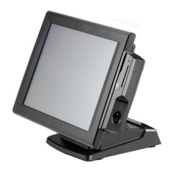
Page 11: Base System
Base System Before you begin, take a few moments to become familiar with the EP-55XX series. Touch Screen Base The rear of the system Right Speaker Left Speaker... -
Page 12: Expandable Options
Expandable Options The two sides of the main display are specially designed for expandable functions and connect with one of the available internal USB ports or PS/2 for operation. Optimized for simple installation, these interfaces do not require any voltage setting adjustments. ... -
Page 13: Convertible Pole-Type/Rear Mount 2Nd Display (Optional)
Convertible Pole-Type/Rear Mount 2nd Display (optional) The pole-type 2nd display is for use with the POS system to display purchase prices and change amounts to customers. It is also capable of displaying advertising messages and announcements. Three types of pole mount display choices are available: a 8.9” LCD monitor, 15” LCD monitor and a 9 cm high, 2 lines with 20 characters each VFD. -
Page 14: Ep-55Xx Series With 8.9" 2Nd Display Dimensions
EP-55XX Series with 8.9” 2nd Display Dimensions (Unit: mm) -
Page 15: Connector Panel
Connector Panel The EP-55XX series's primary connector panel is located at the rear. NOTE: EP-55XX Series's COM6 port is a specialized port, not a standard COM port, and can not transmit the full range of RS-232C signals. Refer to Chapter 4 for COM6 pin assignments. - Page 16 For GA-D525E-C6 main board COM1 COM2 LPT1 COM5 Line-Out USBX2 COM6 for pole Display USBX2 Cash Drawer 12VDC In...
-
Page 17: Standard Hardware And Upgrades
Chapter 2 Standard Hardware and Upgrades Precautions Before performing hardware changes, be sure to carefully read all of the applicable instructions, cautions, and warnings in this guide. WARNING! To reduce the risk of personal injury from electrical shock, hot surfaces, or fire: Disconnect the power cord from the wall outlet and allow the internal system components to cool before touching. -
Page 18: Detaching The Lcd Panel
Detaching the LCD Panel Turn off the system power properly through the operating system, then turn off any external devices. Disconnect the power cord from the power outlet and disconnect any external devices. CAUTION: Regardless of the power-on state, voltage is always present on the main board as long as the system is plugged into an active AC outlet. -
Page 19: Opening Back Cover
Opening Back Cover CAUTION: To prevent loss of work and damage to the system or drive: If you are inserting or removing a drive, shut down the operating system properly, turn off the system, and unplug the power cord. Do not remove a drive while the system is on or in standby mode. - Page 20 5. Unscrew the eight screws as shown below to remove it. 6. Open the metal cover in the direction of the arrow.
-
Page 21: Clearing Cmos
Clearing CMOS The EP-55XX series's configuration (CMOS) may occasionally be corrupted. If it is, it will be necessary to clear the CMOS memory using jumper JP1. Please refer to Chapter 4 for the exact JP1 pin positions. 1. Turn off the system power properly through the operating system, then turn off any external devices. -
Page 22: Compact Flash Card Installation
Compact Flash Card Installation 1. Turn off the system power properly through the operating system, then turn off any external devices. 2. Disconnect the power cord from the power outlet and disconnect any external devices. CAUTION: Regardless of the power-on state, voltage is always present on the main board as long as the system is plugged into an active AC outlet. - Page 23 NOTE: CF card and 2.5” HDD master/slave setting: The system allows the use of both the CF card and hard disk at the same time, however the user will need to set the system BIOS for the preferred boot order. When either a CF card only or 2.5”...
-
Page 24: Additional Memory Installation
The memory socket on the main board can be populated with an industry-standard DIMM. The EP-55XX series comes standard with one preinstalled DIMM. To achieve maximum memory performance, up to 2GB (EP-55XX-AR10) / 4GB(EP-55XX-AR20/30/40) of memory can be changed. CAUTION: You must disconnect the power cord and wait approximately 30 seconds for the power to drain before adding or removing memory cards. - Page 25 3. Remove the panel back cover and metal cover. CAUTION: To avoid scratching the panel while dismantling the system, first place a piece of cloth or cushion on your work surface. 4. Take out the main board and then place the board upside down. 5.
- Page 26 NOTE: When the EP-55XX series RAM cover is installed, please note that the bottom of the thermal pad must be placed over the memory. Ensure the thermal pad and the top surface of the memory is in total contact to prevent the memory from overheating.
-
Page 27: Removing And Replacing The Sata Hard Disk
Removing and Replacing the SATA Hard Disk NOTE: This system does not support Parallel ATA (PATA) hard drives. Before removing the original hard drive, be sure to back up its data so that you can transfer the data to the replacement hard drive. Also, if you are replacing the primary hard drive, make sure you have a recovery disc set to restore the operating system, software drivers, and any software applications that were preinstalled on the system. - Page 28 5. Rotate the HDD box in the direction of the arrow. 6. Remove a screw and slide the HDD box in the direction of the arrow. 7. From the sides of the HDD box, remove all four screws and lift out the hard disk. 8.
- Page 29 NOTE: capacity of a sector is 4096 bytes for 320GB HDD of WD. They are only suitable for Win7 or OS developed later than Win7. To use Microsoft earlier OS such as XP, POS Ready2009 , You should install support tools offered by original supplier to align the performence of HDD.
-
Page 30: Chapter 3 Optional Components And Peripherals
Chapter 3 Optional Components and Peripherals Module Installation 1. Turn off the system power properly through the operating system, then turn off any external devices. 2. Disconnect the power cord from the power outlet and disconnect any external devices. CAUTION: Regardless of the power-on state, voltage is always present on the main board as long as the system is plugged into an active AC outlet. - Page 31 5. Reconnect the power cord and any external devices, then turn on the system. NOTE: The MSR module configuration tool is in the included CD. If you need configure MSR module, please execute the utility according to the procedure specified in Chapter 5.
-
Page 32: Single Msr Module Installation
Single MSR Module Installation 1. Turn off the system power properly through the operating system, then turn off any external devices. 2. Disconnect the power cord from the power outlet and disconnect any external devices. CAUTION: Regardless of the power-on state, voltage is always present on the main board as long as the system is plugged into an active AC outlet. - Page 33 6. Reconnect the power cord and any external devices, then turn on the system. NOTE: The MSR module configuration tool is in the included CD. If you need configure MSR module, please execute the utility according to the procedure specified in Chapter 5.
-
Page 34: Cash Drawer Installation
Cash Drawer Installation NOTE: Before connecting cash drawer to the system, make sure the driver voltage and cable pin assignment of the cash drawer matches the definition of the system's cash drawer port. Please refer to the Cash Drawer Power Select Connector section. -
Page 35: Pole-Type 2Nd Display Module Installation
Pole-Type 2nd Display Module Installation 1. Turn off the system power properly through the operating system, then turn off any external devices. 2. Disconnect the power cord from the power outlet and disconnect any external devices. CAUTION: Regardless of the power-on state, voltage is always present on the main board as long as the system is plugged into an active AC outlet. - Page 36 5. Connect the pole-type 2nd display module’s cable connectors to the EP-55XX series’s COM6 port and VGA port respectively. 6. Reconnect the power cord and any external devices, then turn on VFD/LCD power. Finally, turn on the system power. NOTE: The pole mount VFD module’s configuration utility is in the included CD.
-
Page 37: Rear Mount Vfd Module Installation
Rear Mount VFD Module Installation 1. Turn off the system power properly through the operating system, then turn off any external devices. 2. Disconnect the power cord from the power outlet and disconnect any external devices. CAUTION: Regardless of the power-on state, voltage is always present on the main board as long as the system is plugged into an active AC outlet. -
Page 38: Main Board Configuration
Chapter 4 Main Board Configuration Jumper and Connector Locations of PEB-973A (For EP-55XX-AR10) Connector Allocations Connector Function LPC port 80 daughter card connector SATA and IDE active LED SATA drive power connector Reserved LVDS back light inverter connector USB port 2... - Page 39 Front panel connector COM6 connector Printer port USB port 1, USB port 4 and GIGA LAN RJ-45 connector Speaker out and MIC connector COM1, COM2 connector. Upper is COM1; Lower is COM2 RJ-11 connector +12V DC power input COM5 connector VGA connector CF card socket ( on the solder side )
-
Page 40: Jumper Settings Of Peb-973A (For Ep-55Xx-Ar10)
Jumper Settings of PEB-973A (For EP-55XX-AR10) To set jumper positions, place the jumper shunt over the pins designated in the table (SHORT) or remove (NC) it from the jumper pins and store for future use. Default settings are indicated with a star symbol (). - Page 41 COM6 RI Function Selection (reserved for Pole Display) PIN No. Function Short +5V output Short RI function Short +12V output COM1 RI Function Selection PIN No. Function Short +5V output Short RI function Short +12V output COM2 RI Function Selection PIN No.
-
Page 42: Jumper And Connector Locations Of Peb-973D (For Ep-55Xx-Ar20)
Jumper and Connector Locations of PEB-973D (For EP-55XX- AR20) - Page 43 Connector Allocations Connector Function LVDS Connector VGA Connector Compact Flash Connector J6,J7 SATA Connector SATA Power Connector COM1 & COM2 Connector COM6 Port Pin Header COM5 Port Connector PS/2 Keyboard/Mouse Connector CPU FAN SYS FAN Print Port Connector POWER DC +12V Connector POWER DC +12V Connector Front panel pin header HDD LED Pin header...
-
Page 44: Jumper Settings Of Peb-973D (For Ep-55Xx-Ar20)
Jumper Settings of PEB-973D (For EP-55XX-AR20) To set jumper positions, place the jumper shunt over the pins designated in the table (SHORT) or remove (NC) it from the jumper pins and store for future use. Default settings are indicated with a star symbol (). Clear CMOS Selection PIN No. - Page 45 JP10 COM1 RI Function Selection PIN No. Function Short +5V output Short RI function Short +12V output JP11 COM2 RI Function Selection PIN No. Function Short +5V output Short RI function Short +12V output JP12 COM5 RI Function Selection PIN No.
-
Page 46: Jumper And Connector Locations Of Ins8313B And Ga-D525E-C6 (For Ep-55Xx-Ar30/40)
Jumper and Connector Locations of INS8313B and GA-D525E-C6 (For EP-55XX-AR30/40) - Page 47 Connector Allocations Connector Function MINI_CARD Mini PCIe connector DC_IN DC+12V IN connector DC_OUT DC+12V Out connector COM1 2x5 Pin connector COM3 2x5 Pin connector COM4 2x5 Pin connector COM5 2x5 Pin connector COM6 2x5 Pin connector F_AUDIO Front_Audio connector F_USB 1 USB connector F_USB 2 USB connector...
-
Page 48: Jumper Settings Of Ins8313B And Ga-D525E-C6 (For Ep-55Xx-Ar30/40)
Jumper Settings of INS8313B and GA-D525E-C6 (For EP-55XX- AR30/40) To set jumper positions, place the jumper shunt over the pins designated in the table (SHORT) or remove (NC) it from the jumper pins and store for future use. Default settings are indicated with a star symbol (). LVDS_PWR1 LVDS 3V/5V selection PIN No. -
Page 49: External Com6 Por: Connector Pin Definitions
JCOM1/2/3/4/5/6 For Pin 9 output 5V, 12V or RI PIN No. Function 1-2 Short 3-4 Short RI 5-6 Short USB_PWR1/2/3 Jumper for Stand‐by 5V or VCC 5V selections PIN No. Function 1-2 Short VCC 5V 2-3 Short Stand‐by 5V CLR_COMS1 Clear CMOS Pin‐header PIN No. - Page 50 LCDPWR_CON LCD Power ON/OFF PIN No. Function 1-2 Short 1-2 Open OFF BKLTEN_CON Back light Inverter Enabled/Disabled PIN No. Function 1-2 Short Enable 1-2 Open Disable ...
-
Page 51: Chapter 5 Software Setup
Chapter 5 Software Setup Pre-Installation Requirements This system comes with a variety of drivers for different operating systems. A software CD is included in the package contents. The following section documents the procedures used to install the peripheral. 1. Insert sofeware CD into a system. 2. - Page 52 elect your POS model Number. 6. Select the driver that you want to install and then follow on-screen instructions to install your driver or refer to following procedures specifying how every driver is to be installed.
-
Page 53: Intel Chipset Driver Installation
Intel Chipset Driver Installation 1. Click the Next button on the Welcome screen. 2. Click Yes on the License Agreement screen. 3. Click Next on the Information screen. 4. When installation is complete, click Finish. -
Page 54: Intel Graphics Driver Installation
Intel Graphics Driver Installation Click Next on the Starup screen. 2. Click Next on the Welcome screen. 3. Click Yes on the License Agreement screen. 4. Click Next on the Information screen. 6. When installation is complete, click Finish and 5. -
Page 55: Elo Touch Screen Driver Installation
ELO Touch Screen Driver Installation 1. Click OK on the Welcome screen. 2. Click Unzip on the WinZip Self-Extractor screen. 4. Select Install Serial Touchscreen Drivers, click 3. Select Default installation language, click Next. Next. 5. Click Yes on the License Agreement screen. 6. - Page 56 7. Select COM3, click Next. 8. Click Next to confirm COM port selection. 9. Click Finish. 10. Click Restart Now to apply these change.
-
Page 57: Abon Touch Screen Driver Installation
Abon Touch Screen Driver Installation 1. Click Next on the Welcome screen. 2. Click Next to confirm destination location. 3. Select Install RS232 driver and click Next. 4. Click Install to begin installation. 6. For Windows 7 operating system, click Install 5. - Page 58 7. For Windows XP operating system, click 8. Click OK to reboot the system. Continue anyway. 10. Select Advance and click on the 4 Pts. 9. Run the Touch Tool on the desktop. Calibration button.
-
Page 59: Audio Driver Installation
Audio Driver Installation 2. When installation is complete, click Finish to 1. Click Next on the Welcome screen. restart the system. -
Page 60: Ethernet Driver Installation For Windows Xp
Ethernet Driver Installation for Windows XP 1. Click Next. 2. Click Install. 3. Click Finish. Ethernet Driver Installation for Windows 7 1. Click Install. 2. Click Finish. -
Page 61: Wireless Lan Driver Installation (Optional)
Wireless LAN Driver Installation (optional) Enter the LR802UKN3_802.11bgn folder and then run the IS_AP_STA_RT2870_D.exe. 2. Click Accept on the License Agreement screen. 3. Alternative, and then click Next. 4. For Windows XP operating system, select 5. Click Install. Configuration Tool. 6. - Page 62 8. When installation is complete, the WLAN utility will automatically appear on the desktop.
- Page 63 RFID Driver Installation (optional) 1. First, plug in the RFID Module. 2. Enter the MF320U folder and then run the MifareDemoSetup_PSW00020.exe. 3. Click Next. 4. Click Next to accept the Destination Directory. 5. Click Next after making sure the folder. 6.
-
Page 64: Msr Driver Installation (Optional)
MSR Driver Installation (optional) 1. Plug in MSR module. 2. Select your MSR interface PS2 or USB. 3. For PS2 interface: Run the MSRfgSetup_V1_4R7_PSW00025.exe. For USB interface: Enter the Software folder and then run the HISD_MSR_PSW00003.exe. 4. Follow on-screen instructions to install your MSR driver. -
Page 65: Fingerprint Reader Driver Installation (Optional)
Fingerprint Reader Driver Installation (optional) 1. Plug in the 2-in-1 Fingerprint Reader and MSR module. 2. Enter the SDK folder and then run the setup.exe. 3. Click Next on the Welcome screen. 4. Click Next on the License Agreement screen. 5. - Page 66 9. Wait as the driver is installed. 10. Click Finish. 11. Click Yes to restart the system (required).
-
Page 67: Ic Card Reader Driver Installation (Optional)
IC Card Reader Driver Installation (optional) 1. Plug in the 3-in-1 MSR/I-Button/IC Card Reader module. 2. Enter the EZ100PU Driver folder. 3. Select your POS operating system and then run the setup.exe. 4. Select language, click OK. 5. Click Next on the Welcome screen. 6. -
Page 68: Rear Mount Vfd Driver Installation (Optional)
Rear Mount VFD Driver Installation (optional) The EP-55XX rear mount VFD port is a USB interface. The rear mount VFD uses a Serial interface, so in order to enable it you must install the included USB-to-Serial interface driver. 1. First, plug in the VFD Module. 2. -
Page 69: System Driver Installation (Required For Cash Drawer)
System Driver Installation (required for Cash Drawer) 1. Click Next on the Welcome screen. 2. Click Install on the Ready to Install screen. 3. Click Finish on the Completing installation screen. A system restart is required to complete the installation. -
Page 70: Opos Cco Driver Installation
OPOS CCO Driver Installation Before installing the OPOS driver, please make sure the System Driver has been installed. The OPOS driver for the EP-55XX series supports the Cash Drawer, MSR, I-Button (KeyLock), RFID, VFD (Line- Display). 1. Click Next on the Welcome screen. 2. - Page 71 7. Click Finish on the Installation Complete screen.
-
Page 72: Opos Driver Installation
OPOS Driver Installation 1. Click Next on the Welcome screen. 2. Click Install on the Setup screen. 3. Click Finish on the Completing installation screen. -
Page 73: Appendix A. Sample C++ Cash Drawer Code For Windows
Appendix A. Sample C++ Cash Drawer Code for Windows NOTE: Requires installation of System Driver. Refer to the System Driver Installation section for instructions. //1. Open Cash Drawer // IOCTL Codes #define GPD_TYPE 40000 #define ADV_OPEN_CTL_CODE CTL_CODE(GPD_TYPE, 0x900, METHOD_BUFFERED, FILE_ANY_ACCESS) #define ADV_STATUS_CTL_CODE CTL_CODE(GPD_TYPE, 0x901, METHOD_BUFFERED,... - Page 74 bRet = DeviceIoControl(hFile, ADV_STATUS_CTL_CODE, NULL, 0, &ReadByte, sizeof(ReadByte), &ulBytesReturned, NULL); (bRet == FALSE || ulBytesReturned != 1) AfxMessageBox("Failed to Read from cash drawer driver"); CloseHandle(hFile); return; else AfxMessageBox(ReadByte ? “Drawer Open”: “Drawer Closed”); CloseHandle(hFile);...
-
Page 75: Appendix B. Sample Vb.net Cash Drawer Code For Windows
Appendix B. Sample VB.NET Cash Drawer Code for Windows NOTE: Requires installation of System Driver. Refer to the System Driver Installation section for instructions. Private Declare Function CreateFile "kernel32" Alias "CreateFileA" (ByVal lpFileName String, ByVal dwDesiredAccess Integer, ByVal dwShareMode Integer, ByVal lpSecurityAttributes IntPtr,... - Page 76 (iRet = 0 iBytesRtn <> 1) Then MsgBox("Error opening ADVSYS.sys. Error = " & Err.LastDllError) End If End Sub Private Sub Timer1_Tick(ByVal sender System.Object, ByVal System.EventArgs) Handles Timer1.Tick iBytesRtn As Integer iRet Integer, iStatus As Integer ' Get Drawer Status iRet = DeviceIoControl(DeviceHandle, ADV_STATUS_CTL_CODE, 0, 0, iStatus, 4, iBytesRtn, 0) (iRet = 0 iBytesRtn <>...
-
Page 77: Appendix C. Sample Vb6.0 Cash Drawer Code For Windows
Appendix C. Sample VB6.0 Cash Drawer Code for Windows NOTE: Requires installation of System Driver. Refer to the System Driver Installation section for instructions. Option Explicit On Private Declare Function CreateFile "kernel32" Alias "CreateFileA" (ByVal lpFileName String, ByVal dwDesiredAccess Long, ByVal dwShareMode Long,... - Page 78 Private Sub Form_Load() '-1673527296 Come from c code (40000 <<16) ADV_OPEN_CTL_CODE = CTL_CODE(-1673527296, &H900, METHOD_BUFFERED, FILE_ANY_ACCESS) ADV_STATUS_CTL_CODE = CTL_CODE(-1673527296, &H901, METHOD_BUFFERED, FILE_ANY_ACCESS) DeviceHandle = CreateFile("\\.\ADVSYS", GENERIC_READ GENERIC_WRITE, FILE_SHARE_READ FILE_SHARE_WRITE, SA, OPEN_EXISTING, FILE_ATTRIBUTE_NORMAL, 0) DeviceHandle = INVALID_HANDLE_VALUE Then 'Failed to Open Cash Drawer Driver MsgBox("Error opening ADVSYS.sys.
Need help?
Do you have a question about the EP-55XX-AR10 and is the answer not in the manual?
Questions and answers