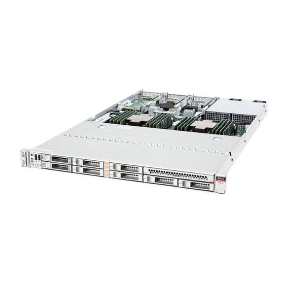
Oracle SPARC S7-2 Installation Manual
Compact cloud server
Hide thumbs
Also See for SPARC S7-2:
- Service manual (258 pages) ,
- Installation manual (102 pages) ,
- Service manual (156 pages)
Table of Contents
Advertisement
Advertisement
Table of Contents

Related Manuals for Oracle SPARC S7-2


Summary of Contents for Oracle SPARC S7-2
- Page 1 SPARC S7-2 Server Installation Guide Part No: E72375-02 July 2016...
- Page 3 Oracle. Oracle Corporation and its affiliates will not be responsible for any loss, costs, or damages incurred due to your access to or use of third-party content, products, or services, except as set forth in an applicable agreement between you and Oracle.
- Page 4 Oracle Corporation et ses affiliés déclinent toute responsabilité ou garantie expresse quant aux contenus, produits ou services émanant de tiers, sauf mention contraire stipulée dans un contrat entre vous et Oracle. En aucun cas, Oracle Corporation et ses affiliés ne sauraient être tenus pour responsables des pertes subies, des coûts occasionnés ou des dommages causés par l'accès à...
-
Page 5: Table Of Contents
Contents Using This Documentation ................. 7 Understanding the Server ................... 9 Conceptual Overview .................. 9 Oracle Software in Silicon Features ............ 9 Installation Task Overview ................ 10 Server Overview ................... 11 Front Panel Components (Installation) ............... 12 Rear Panel Components (Installation) ............... 13 Confirming Specifications ................. 15 Physical Specifications ................... 15 Electrical Specifications .................. 16 Environmental Specifications ................ 17... - Page 6 ▼ Configure the Preinstalled Oracle Solaris OS ......... 60 ▼ Reach a State to Install a Fresh OS (Oracle ILOM CLI) ...... 61 ▼ Reach a State to Install a Fresh OS (Oracle ILOM Web Interface) .... 63 Assigning a Static IP Address to the SP ............ 65 ▼...
-
Page 7: Using This Documentation
Using This Documentation Overview – Describes how to install the SPARC S7-2 server ■ Audience – Technicians, system administrators, and authorized service providers ■ Required knowledge – Experience with the Oracle Solaris Operating System, ■ troubleshooting, and replacing hardware Product Documentation Library Documentation and resources for this product and related products are available at http://www. - Page 8 SPARC S7-2 Server Installation Guide • July 2016...
-
Page 9: Understanding The Server
“Powering On the Server for the First Time” on page 57 ■ Conceptual Overview The SPARC S7-2 servers provide enterprise class performance and Software in Silicon features in significantly lower-cost form factors. Newly designed microprocessors and hardware provides high level of system integration, excellent throughput, low memory latency, and high bandwidth IO interconnect. -
Page 10: Installation Task Overview
Oracle Software in Silicon functionality, refer to: https://www.oracle. com/servers/sparc/software-in-silicon.html. For more details on ADI, refer to the Oracle Solaris 11.3 documentation. To use DAX, you must configure the Oracle Database 12c in- memory feature. For instructions, refer to “Using the In-Memory Column Store” at: http:// docs.oracle.com/database/121/ADMIN/memory.htm#ADMIN14257... -
Page 11: Server Overview
Server Overview Steps Description Links Connect the power cords to the server, configure the Oracle “Powering On the Server for the First Time” on page 57 ILOM on the SP, power on the server for the first time, and set up the operating system. -
Page 12: Front Panel Components (Installation)
“Rear Panel Components (Installation)” on page 13 ■ Front Panel Components (Installation) No. Description Description Serial number Server Overtemp LED (amber) Locator LED (white) Drive 0 (HDD/SDD) Two USB 2.0 connectors Drive 1 (HDD/SDD) SPARC S7-2 Server Installation Guide • July 2016... -
Page 13: Rear Panel Components (Installation)
Rear Panel Components (Installation) No. Description Description Service Action Required LED Drive 2 (HDD/SDD) or NVMe 0 (amber) Power/OK LED (green) Drive 3 (HDD/SDD) or NVMe 1 Power button Drive 4 (HDD/SDD) or NVMe 2 SP OK/Fault LED (green or Drive 5 (HDD/SDD) or NVMe 3 amber) Fan Service Action Required LED... - Page 14 “Front Panel Components (Installation)” on page 12 ■ “Rear Cable Connections and Ports” on page 51 ■ “Connect Server Cables” on page 55 ■ “Install the Cable Management Arm” on page 39 ■ SPARC S7-2 Server Installation Guide • July 2016...
-
Page 15: Confirming Specifications
Confirming Specifications These topics provide the technical information and airflow precautions you need to install the server. “Physical Specifications” on page 15 ■ “Electrical Specifications” on page 16 ■ “Environmental Specifications” on page 17 ■ “Airflow Precautions” on page 18 ■... -
Page 16: Electrical Specifications
23.4 W Maximum server configuration specification under nominal temperature and voltage conditions (SPARC S7-2, Two 4.267GHz S7 Processors, 16 64GB DDR4 DIMMS, 4 SAS + 4 NVMe-SFF drives , 1 Internal HBA card, 3 PCIe cards) Idle AC input power... -
Page 17: Environmental Specifications
Threshold: 13-mm threshold height at 0.65 m/s impact velocity Vibration 0.15 G (z-axis), 0.5 G (z-axis), 0.10 G (x-, y-axes), 5- 0.25 G (x-, y-axes), 5-500Hz swept sine 500Hz swept sine Related Information SPARC S7-2 Server Safety and Compliance Guide ■ Confirming Specifications... -
Page 18: Airflow Precautions
When servicing server internal components, ensure that air ducts, baffles, and filler panels ■ are properly installed. Route cables so that they do not interfere with airflow. ■ Related Information “Rack Cautions” on page 27 ■ “Physical Specifications” on page 15 ■ SPARC S7-2 Server Installation Guide • July 2016... - Page 19 Airflow Precautions “Electrical Specifications” on page 16 ■ “Environmental Specifications” on page 17 ■ Confirming Specifications...
- Page 20 SPARC S7-2 Server Installation Guide • July 2016...
-
Page 21: Preparing For Installation
Preparing for Installation These topics detail the precautions to follow, the tools to assemble, and the tasks to perform prior to installing the server. Step Description Links Confirm that you received all the items you ordered. “Shipping Kit” on page 21 Review safety and ESD precautions “Handling Precautions”... -
Page 22: Handling Precautions
Caution - The server weighs approximately 43 lb (19.5 kg). Two people are required to lift and Caution - mount this server into a rack enclosure when using the procedures in this document. SPARC S7-2 Server Installation Guide • July 2016... -
Page 23: Esd Precautions
“Physical Specifications” on page 15 ■ “Installing the Server” on page 25 ■ SPARC S7-2 Server Getting Started Guide ■ ESD Precautions Electronic equipment is susceptible to damage by static electricity. Use a grounded antistatic wrist strap, foot strap, or equivalent safety equipment to prevent electrostatic damage when you install or service the servers. - Page 24 ASCII terminal ■ Workstation ■ Terminal server ■ Patch panel connected to a terminal server ■ Related Information “Handling Precautions” on page 22 ■ “ESD Precautions” on page 23 ■ Server Service ■ SPARC S7-2 Server Installation Guide • July 2016...
-
Page 25: Installing The Server
Installing the Server These topics describe how to install the server into a rack using the rail assembly in the rackmount kit. Perform these procedures if you purchased the rail assembly. In this guide, the term rack means either an open rack or a closed cabinet. Note - Step Description... -
Page 26: Optional Components
80 cm (31.5 inches) without the cable management arm. Clearance width between front and rear Distance between structural supports and cable troughs is at least mounting planes 45.6 cm (18 inches). SPARC S7-2 Server Installation Guide • July 2016... -
Page 27: Rack Cautions
Rack Cautions Item Requirement Minimum clearance for service access ■ Clearance, front of server: 123.2 cm (48.5 inches) ■ Clearance, rear of server: 91.4 cm (36 inches) Related Information “Physical Specifications” on page 15 ■ “Handling Precautions” on page 22 ■... -
Page 28: Rackmount Kit Contents
The rackmount kit contains two slide-rails, two mounting brackets, and optional securing screws. Refer to the rackmount kit installation card for instructions on how to install your server Note - into a four-post rack, using the slide-rail and cable management arm options. SPARC S7-2 Server Installation Guide • July 2016... -
Page 29: Stabilize The Rack
Stabilize the Rack Description Slide-rails Mounting brackets Four M4 x 5 fine-pitch mounting bracket securing screws (optional) Installation card Related Information “Rack Compatibility” on page 26 ■ Stabilize the Rack To reduce the risk of personal injury, stabilize the rack by extending all anti-tilt Caution - devices before installing the server. -
Page 30: Install Mounting Brackets Onto The Server
Position a mounting bracket against the chassis so that the slide-rail lock is at the server front, and the five keyhole openings on the mounting bracket are aligned with the five locating pins on the side of the chassis. SPARC S7-2 Server Installation Guide • July 2016... -
Page 31: Mark The Rackmount Location
Mark the Rackmount Location Description Chassis front Slide-rail lock Mounting bracket Mounting bracket clip With the heads of the five chassis locating pins protruding through the five keyhole openings in the mounting bracket, pull the mounting bracket toward the front of the chassis until the mounting bracket clip locks into place with an audible click. - Page 32 Mark the mounting holes for the rear slide-rails. Related Information “Rack Compatibility” on page 26 ■ “Install Mounting Brackets Onto the Server” on page 30 ■ “Attach Tool-less Slide-Rail Assemblies” on page 34 ■ SPARC S7-2 Server Installation Guide • July 2016...
-
Page 33: Install Ac Power Cables And Slide-Rails
Install AC Power Cables and Slide-Rails Install AC Power Cables and Slide-Rails Prior to installing the slide-rails into the rack, install right-angle AC power cables into the left-side and right-side PDU electrical sockets for the servers you are going to rack mount. Install the slide-rails into the rack. -
Page 34: Attach Tool-Less Slide-Rail Assemblies
Attach Tool-less Slide-Rail Assemblies “Attach Tool-less Slide-Rail Assemblies” on page Attach Tool-less Slide-Rail Assemblies Use this procedure to attach tool-less slide-rail assemblies to the rack. SPARC S7-2 Server Installation Guide • July 2016... - Page 35 Attach Tool-less Slide-Rail Assemblies Orient the slide-rail assembly so that the ball-bearing track is forward and locked in place. Description Slide-rail Ball-bearing track Locking mechanism Installing the Server...
- Page 36 Repeat Step 1 through Step 3 to attach the slide-rail assembly to the other side of the rack. Related Information “Install Mounting Brackets Onto the Server” on page 30 ■ SPARC S7-2 Server Installation Guide • July 2016...
-
Page 37: Install The Server Into The Slide-Rail Assemblies
Install the Server Into the Slide-Rail Assemblies “Mark the Rackmount Location” on page 31 ■ “Install the Server Into the Slide-Rail Assemblies” on page 37 ■ Install the Server Into the Slide-Rail Assemblies Use this procedure to install the server chassis, with mounting brackets, into the slide-rail assemblies that are mounted to the rack. - Page 38 Continue pushing the server into the rack until the slide-rail locks (on the front of the mounting brackets) engage the slide-rail assemblies. SPARC S7-2 Server Installation Guide • July 2016...
-
Page 39: Install The Cable Management Arm
Install the Cable Management Arm You will hear an audible click. Verify that the server is securely mounted in the rack and that the slide-rail locks are Caution - engaged with the mounting brackets before you install the optional cable management arm. Related Information “Install the Cable Management Arm”... - Page 40 SPARC S7-2L cable covers Ensure that the correct cable covers for your server are installed on the CMA. The SPARC S7-2 uses the flat cable covers. Ensure that the six Velcro straps are threaded into the CMA. SPARC S7-2 Server Installation Guide • July 2016...
- Page 41 Install the Cable Management Arm Ensure that the two Velcro straps located on the front slide bar are threaded through Note - the opening in the top of the slide bar. This prevents the Velcro straps from interfering with the expansion and contraction of the slide bar when the server is extended out of the rack and returned into the rack.
- Page 42 Insert the CMA's connector B into the front slot on the right slide-rail until it locks into place with an audible click (frames 1 and 2). The connector B tab (callout 1) goes into the slide-rail front slot (callout 2). SPARC S7-2 Server Installation Guide • July 2016...
- Page 43 Install the Cable Management Arm Gently tug on the right side of the front slide bar to verify that connector B is properly seated. Description Connector B tab Right slide-rail front slot Install the CMA's connector C into the right slide-rail. Installing the Server...
- Page 44 To prepare the CMA's connector D for installation, remove the tape that secures the slide-rail latching bracket to connector D and ensure that the latching bracket is properly aligned with connector D (frames 1 and 2). SPARC S7-2 Server Installation Guide • July 2016...
- Page 45 Install the Cable Management Arm The CMA is shipped with the slide-rail latching bracket taped to connector D. You must Note - remove the tape before you install this connector. Install the CMA's connector D into the left slide-rail. While holding the slide-rail latching bracket in place, insert connector D and its associated slide-rail latching bracket into the left slide-rail until connector D locks into place with an audible click (frames 1 and 2).
- Page 46 For instructions for stabilizing the rack, see “Stabilize the Rack” on page Slowly pull the server out of the rack until the slide-rails reach their stops. Inspect the attached cables for any binding or kinks. SPARC S7-2 Server Installation Guide • July 2016...
- Page 47 Install the Cable Management Arm Verify that the CMA extends fully with the slide-rails. Return the server to the rack. Simultaneously pull and hold the two green release tabs (one on each side of the server) toward the front of the server while you push the server into the rack.
- Page 48 Velcro straps. Route the cables through the cable troughs in this order: First through the front-most cable trough Then through the small cable trough SPARC S7-2 Server Installation Guide • July 2016...
- Page 49 Install the Cable Management Arm Then through the rear-most cable trough When securing the cables with the Velcro straps located on the front slide bar, ensure Note - that the Velcro straps do not wrap around the bottom of the slide bar, otherwise, expansion and contraction of the slide bar might be hindered when the server is extended from the rack and returned to the rack.
- Page 50 SPARC S7-2 Server Installation Guide • July 2016...
-
Page 51: Cabling The Server
“Powering On the Server for the First Time” on page 57 ■ Rear Cable Connections and Ports The following figure shows the locations of cable connectors and ports on the back of the SPARC S7-2 and the cables and devices that you would typically connect to them. Cabling the Server... - Page 52 AC power cables are connected and the server has not yet been connected to a terminal, PC, or workstation. Note - Oracle ILOM will signal a fault on any installed power supply that is not connected to an AC power source, since it might indicate a loss of redundancy. Ethernet ports (0-3) The four 10-Gigabit Ethernet ports enable you to connect the system to the network.
-
Page 53: Ser Mgt Port Pinout
The SER MGT RJ-45 port, located on the rear panel, provides an TIA/EIA-232 serial Oracle/ Cisco standard connection to the SP. This port is the default connection to the Oracle ILOM system controller. For DTE to DTE communications, use an RJ-45 cable that is set up for a null modem configuration, in which the transmit and receive signals cross over. - Page 54 SER MGT Port Pinout This example shows a diagram of an RJ-45 to DB-9 conversion. SPARC S7-2 Server Installation Guide • July 2016...
-
Page 55: Connect Server Cables
Connect Server Cables Related Information “Rear Cable Connections and Ports” on page 51 ■ “Connect Server Cables” on page 55 ■ Connect Server Cables Observe all safety requirements and prepare for installation. “Preparing for Installation” on page Gather required network information. Netmask ■... - Page 56 ■ “Reach a State to Install a Fresh OS (Oracle ILOM CLI)” on page 61 ■ “Reach a State to Install a Fresh OS (Oracle ILOM Web Interface)” on page 63 ■ SPARC S7-2 Server Installation Guide • July 2016...
-
Page 57: Powering On The Server For The First Time
“Configure the Preinstalled Oracle Solaris OS” on page 60 Configure the preinstalled OS, or install a fresh “Configure the Preinstalled Oracle Solaris OS” on page 60 “Reach a State to Install a Fresh OS (Oracle ILOM Web Interface)” on page 63 3. (Optional) Configure the NET MGT port to use a static IP “Assign a Static IP Address to the NET MGT Port”... - Page 58 Administrator account as soon as possible after your initial login to Oracle ILOM. If you find this default Administrator account has already been changed, contact your system administrator to obtain an Oracle ILOM user account with Administrator privileges.
-
Page 59: Oracle Ilom System Console
■ Oracle ILOM System Console When you power on the system, the boot process begins under the control of the Oracle ILOM system console. The system console displays status and error messages generated by firmware- based tests that are run during system startup. -
Page 60: Installing The Os
“Reach a State to Install a Fresh OS (Oracle ILOM CLI)” on page 61 ■ “Reach a State to Install a Fresh OS (Oracle ILOM Web Interface)” on page 63 ■ “Assign a Static IP Address to the NET MGT Port” on page 67 ■... -
Page 61: Reach A State To Install A Fresh Os (Oracle Ilom Cli)
Accept the default date and time, or change the values. root Password Type the root password twice. This password is for the superuser account for the Oracle Solaris OS on this server. This password is not the SP password. Log in to the server. - Page 62 Are you sure you want to reset /System (y/n)? y Performing reset on /System In Oracle ILOM 3.1, the name space for /SYS was replaced with /System. You can use Note - the legacy name in a command at any time, but to expose the legacy name in the output, you must enable it with ->...
-
Page 63: Reach A State To Install A Fresh Os (Oracle Ilom Web Interface)
“Reach a State to Install a Fresh OS (Oracle ILOM CLI)” on page 61 ■ “Reach a State to Install a Fresh OS (Oracle ILOM Web Interface)” on page 63 ■ “Assign a Static IP Address to the NET MGT Port” on page 67 ■... - Page 64 Reach a State to Install a Fresh OS (Oracle ILOM Web Interface) If you have not done so, perform these tasks to access the Oracle ILOM web interface on the server: In a browser on the same network as the system, type the IP address.
-
Page 65: Assigning A Static Ip Address To The Sp
If your network does not use DHCP, the NET MGT port is not operational until you configure network settings for the service processor. If you are unable to use DHCP on your network, you must connect to the Oracle ILOM Note - on the SP using the SER MGT port to configure the NET MGT port for your network. -
Page 66: Log In To The Sp (Ser Mgt Port)
Log In to the SP (SER MGT Port) After the SP boots, access the Oracle ILOM CLI to configure and manage the server. The Oracle ILOM CLI prompt (->) is displayed the first time the SP is booted. The default configuration provides an Oracle ILOM CLI root user account. -
Page 67: Assign A Static Ip Address To The Net Mgt Port
Assign a Static IP Address to the NET MGT Port After the root password has been set, on subsequent reboots, the Oracle ILOM CLI Note - login prompt is displayed. Use the new password for all subsequent root log ins. - Page 68 outofbandmacaddress = xx:xx:xx:xx:xx:xx pendingipaddress = service-processor-IPaddr pendingipdiscovery = static pendingipgateway = gateway-IPaddr pendingipnetmask = 255.255.255.0 pendingmanagementport = MGMT sidebandmacaddress = xx:xx:xx:xx:xx:xx state = enabled -> Set the changes to the SP network parameters. SPARC S7-2 Server Installation Guide • July 2016...
- Page 69 “Configure the Preinstalled Oracle Solaris OS” on page 60 ■ “Reach a State to Install a Fresh OS (Oracle ILOM CLI)” on page 61 ■ “Reach a State to Install a Fresh OS (Oracle ILOM Web Interface)” on page 63 ■ Oracle ILOM documentation ■...
- Page 70 SPARC S7-2 Server Installation Guide • July 2016...
-
Page 71: Index
30 gateway IP address, 55 clearance service, 15 conceptual overview, 9 configuring information required, 55 Oracle Solaris, 60 handling precautions, 22 confirming specifications, 15 handshaking for serial terminal, 55 cooling fans, 11 heat dissipation specification, 16... -
Page 72: Sparc S7-2 Server Installation Guide • July
26 Oracle ILOM, 59 Oracle Solaris configuration parameters, 60 configuring the preinstalled OS, 60 SER MGT port installing a fresh OS (Oracle ILOM CLI), 61 initial power on, 55 SPARC S7-2 Server Installation Guide • July 2016... - Page 73 Index pinouts, 53 rear, 13 serial crossover cable, 53 serial terminal settings, 55 server overview, 9 service clearance, 15 vibration specifications, 17 service processor voltage specifications, 16 show command, 67 Service Required LED, 12 shipping kit contents, 21 show command, 67 site planning specifications, 15 weight specification, 15 Software in Silicon, 9...
- Page 74 SPARC S7-2 Server Installation Guide • July 2016...
Need help?
Do you have a question about the SPARC S7-2 and is the answer not in the manual?
Questions and answers