
Related Manuals for SMC Networks EX120-SDN1-X2


Summary of Contents for SMC Networks EX120-SDN1-X2
- Page 1 No.EX##-OME0015-C PRODUCT NAME SI unit for DeviceNet MODEL / Series / Product Number EX120-SDN1(-X2/-X26/-X77) EX121-SDN1(-X2/-X26/-X77) EX122-SDN1(-X2/-X26/-X77) EX124U/D-SDN1(-X2/-X26/-X77)
-
Page 2: Table Of Contents
Contents Safety Instructions How to Order Summary of Product elements Installation and wiring Installation Wiring LED indication and settings DeviceNet Objects Troubleshooting and Maintenance Specifications Specifications Dimensions Accessories No.EX##-OME0015-C... -
Page 3: Safety Instructions
Safety Instructions These safety instructions are intended to prevent hazardous situations and/or equipment damage. These instructions indicate the level of potential hazard with the labels of "Caution", "Warning" or "Danger". They are all important notes for safety and must be followed in addition to International ∗... - Page 4 Caution The product is provided for use in manufacturing industries. The product herein described is basically provided for peaceful use in manufacturing industries. If considering using the product in other industries, consult SMC beforehand and exchange specifications or a contract if necessary. If anything is unclear, contact your nearest sales branch.
- Page 5 Operator ♦This operation manual is intended for those who have knowledge of machinery using pneumatic equipment, and have sufficient knowledge of assembly, operation and maintenance of such equipment. Only those persons are allowed to perform assembly, operation and maintenance. ♦Read and understand this operation manual carefully before assembling, operating or providing maintenance to the product.
- Page 6 ■NOTE ○Follow the instructions given below when designing, selecting and handling the product. •The instructions on design and selection (installation, wiring, environment, adjustment, operation, described below must also be followed. maintenance, etc.) ∗Product specifications •When conformity to UL is required, the SI unit should be used with a UL1310 Class2 power supply. •The SI unit is a approved product only if they have a mark on the body.
- Page 7 ∗Environment •Select the proper type of protection according to the environment of operation. In case of IP20, avoid use in the place where water and oil scatter. IP65 protection is achieved when the following conditions are met. (1) The units are connected properly with fieldbus cable with M12 connector and power cable with M12 (M8) connector. (2) Suitable mounting of each unit and manifold valve.
-
Page 8: How To Order
How to Order No.EX##-OME0015-C... -
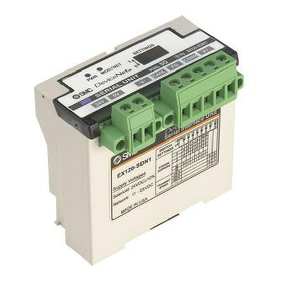
Page 9: Summary Of Product Elements
Summary of Product Parts ○EX120-SDN1(-X2/-X26/-X77) ○EX121-SDN1(-X2/-X26/-X77) ○EX122-SDN1(-X2/-X26/-X77) No.EX##-OME0015-C... - Page 10 ○EX124U/D-SDN1(-X2/-X26/-X77) Element Description The power supply connector, provided as an accessory, is used to supply the ∗ 1 power for the solenoid valves. Power supply connector EX12∗-SDN1/-X2: Green EX12∗-SDN1-X26/-X77: Grey ∗ 1 is used The communication connector to connect to the DeviceNet line.
-
Page 11: Installation And Wiring
Installation and wiring ■Installation Connect the valve manifold to the SI unit when installing the SI unit. Refer to the catalogue for the valve manifold dimensions. ■Wiring ○Communication wiring MSTB2, 5/5-STF-5, 08AU connectors manufactured by Phoenix Contact are attached to the SI unit for mounting on the cable. - Page 12 ○DeviceNet Media Topology A shielded twisted pair cable for DeviceNet should be used. The maximum cable length depends on the communication speed and the cable type used. <Communication speed [kbps] and maximum bus cable length> Max. cable length for network Communication speed Drop line length Cummulative Drop...
- Page 13 ○Power supply wiring (Power supply for solenoid valve) MSTB2, 5/2-STF-5, 08 connectors manufactured by Phoenix Contact are attached to the SI unit for mounting on the cable. The power supply connector for the solenoid valve is wired in the following way. The connector screws should be tightened securely with a tightening torque of 0.5 to 0.6 Nm.
-
Page 14: Led Indication And Settings
LED indication and settings ○LED display EX120-SDN1 (-X2/-X26/-X77) EX124D-SDN1 (-X2/-X26/-X77) EX121-SDN1 (-X2/-X26/-X77) EX124U-SDN1 (-X2/-X26/-X77) EX122-SDN1 (-X2/-X26/-X77) Display Green LED is ON when power for communication is supplied. LED is off The unit is not on-line or the power supply for communication is off. Green flashing Connection stand-by (on-line status) MOD/NET... - Page 15 ○Switch setting (EX12∗-SDN1, EX12∗-SDN1-X2) Use the 8 way switch on the SI unit to set the node address (MAC_ID) and DeviceNet communication speed. Note 1. Open the cover of the SI unit and use a flat blade screwdriver to set the switches. 2.
- Page 16 ○Settings via network (EX12∗-SDN1, EX12∗-SDN1-X2) It is possible to set the output operation via the network, when a communication error is generated, in accordance with the procedure below. • Output operation setting at the time of communication error 1) The instant attribute value below is set to 1 via the network Class Instance Attribute...
- Page 17 ○Switch settings (EX12∗-SDN1-X26/-X77) Use the 10 way switch on the SI unit to set the node address (MAC_ID) and DeviceNet communication speed. Note 1. Open the cover of the SI unit and use a flat blade screwdriver to set the switches. 2.
- Page 18 •HOLD/CLEAR setting (Switch No.9) Set the output condition when a communication error is generated. (All outputs will be set with the same ∗ conditions. The default setting of this function is both switches “OFF”, so the default value is set to CLEAR. 0: OFF 1: ON Switch No.
- Page 19 •Output condition setting during I/O connection time-out 1) The instant attribute value below is set to 1 via the network. Class Instance Attribute Description Value 0: Switch No.9 setting valid Hold Clear (Default) 68h (104) (SMC) (Connection Delete) 1: Fault action valid Class Instance Attribute...
- Page 20 ○I/O memory map The SI unit occupies the memory area of 16 output points (2 bytes). The SI unit cannot be connected to an input device, but occupies memory areas of 16 input points (2 bytes) ∗ as a mirror function of output data. ∗: Mirror function: Output data received by the SI unit will be transmitted as input data exactly as it is.
- Page 21 ○Output number assignment Combinations of the output data and the valve manifold ∗: Output No. starts from 0, and will be assigned to the valves in order from the SI unit mounted side. ∗: Standard wiring on the manifold is for double-solenoid valves and output number starts A side and B side in that order as shown in the figure a.
-
Page 22: Devicenet Tm Objects
DeviceNet Objects ○DeviceNet Objects The SI unit supports the DeviceNet object classes below, with pneumatic valves as the device type. ∗: Hexadecimal value is used for □□h indication. Class code Object class Identity Message Router DeviceNet Assembly DeviceNet Connection Discrete Output Point Parameter SMC SI (SMC Specific) 1. - Page 23 1-4. Instance common service Service code Description Reset Get_Attribute_Single 1-5. Specific service None. 2. Message Router Object (Class ID: 02h) 2-1. Class attribute Access rule Description Value 2-2. Class common service Service code Description 2-3. Instance attribute Access rule Description Value 2-4.
- Page 24 3-3. Instance attribute Access rule Description Value ∗ 1 Get/Set MAC ID 0-63 ∗ 1 Get/Set Baud Rate Get/Set Bus Off Interrupt (BOI) Get/Set Bus Off Counter 0-255 Allocation Information MAC ID Switch Changed Baud Rate Switch Changed MAC ID Switch Value 0-63 Baud Rate Switch Value Quick Connect...
- Page 25 4-4. Solenoid status assembly iInstance (EX12∗-SDN1/-X2 supports the following functions, but EX12∗-SDN1-X26 and -X77 do not.) Type Description Byte Input 16 Solenoid status Points The data format is shown below. (Mirror data of the output data) Data Byte offset bit7 bit0 IBn+0 (OUT7)
- Page 26 5. DeviceNet Connection Object (Class ID: 05h) 5-1. Class attribute Access rule Description Value 5-2. Class common service Service code Description 5-3. Instance attribute1 (Explicit message) Access rule Description Value State Instance_type TransportClass_trigger DeviceNet _produced_connection_id DeviceNet _consumed_connection_id DeviceNet _initial_comm_characteristics Produced_connection_size FFFFh Consumed_connection_size FFFFh...
- Page 27 5-4. Instance attribute2 (I/O: Poll message) Access rule Description Value State Instance_type TransportClass_trigger DeviceNet _produced_connection_id DeviceNet _consumed_connection_id DeviceNet _initial_comm_characteristics 02h: EX12∗-SDN1/-X2 Produced_connection_size 00h: EX12∗-SDN1-X26/-X77 Consumed_connection_size Get/Set Expected_packet_rate Get/Set Watchdog_timeout_action 6: EX12∗-SDN1/-X2 Produced_connection_path_length 0: EX12∗-SDN1-X26/-X77 20h, 04h, 24h, 05h, 30h, 03h: Produced_connection_path EX12∗-SDN1/-X2 None: EX12∗-SDN1-X26/-X77...
- Page 28 6. Discrete Output Point Object (Class ID: 09h) 6-1. Class attribute Access rule Description Value 6-2. Class common service Service code Description 6-3. Instance attribute Access rule Description Value 0: OFF Get/Set Value 1: ON Status -: Unused 0: Fault value ∗...
- Page 29 7. Parameter Object (Class ID: 0Fh) 7-1. Class attribute Access rule Description Value Max. Instance Parameter Class Descriptor Configuration Assembly Instance 7-2. Class common service Service code Description Get_Attribute_Single 7-3. Instance attribute 5: Hold/Clear (Timeout) Access rule Description Value 0: Clear setting valid (EX12∗-SDN1/-X2) Parameter Value Switch No.9 setting valid (EX12∗-SDN1-X26/-X77) 1: Fault action valid...
- Page 30 8. SMC SI Object (Class ID: 64h) 8-1. Class attribute Access rule Description Value 8-2. Class common service Service code Service name 8-3. Instance attribute Access rule Description Value 0: Clear setting valid (EX12∗-SDN1/-X2) Hold/Clear (Timeout) Switch No.9 setting valid (EX12∗-SDN1-X26/-X77) 1: Fault action valid 0: Follow the setting of ID104 Hold/Clear (Delete)
-
Page 31: Troubleshooting And Maintenance
Troubleshooting and maintenance Troubleshooting flowchart When any malfunction is observed, perform the following troubleshooting. Refer to fault SI unit does not SI unit PWR LED No.1 operate normally is OFF SI unit MOD/NET LED Refer to fault No.2 is OFF Refer to fault SI unit MOD/NET LED No.3... - Page 32 Troubleshooting table Fault No.1 Problem Possible cause Investigation method Countermeasures Re-wire the power supply Incorrect wiring of cable. (Replace the cable if it the power supply Check the power supply cable connections and is damaged). for DeviceNet check for broken wires. Correct the wiring of the communication SI unit PWR...
- Page 33 Fault No.3 Problem Possible cause Investigation method Countermeasures MAC ID Check that there is no MAC ID duplication Correct the MAC ID settings. duplication error between the master and slave. Check that the length of the communication cable is suitable for the communication speed, Correct the wiring and check for terminators at both ends, and check settings.
- Page 34 Fault No. 5 Problem Possible cause Investigation method Countermeasures Re-wire the DeviceNet Incorrect wiring of cable. (Replace the cable if it the power supply Check the DeviceNet cable connections and is damaged). for DeviceNet check for broken wires. SI unit Rectify the wiring of the communication MOD/NET LED...
- Page 35 <Precautions for replacement of SI unit> 1. Be sure to turn the power OFF before replacing the SI unit. Otherwise injury or SI unit malfunction can result. 2. Check the wiring before supplying power. Otherwise damage to the SI unit can result in some wiring conditions, causing breakdown or malfunction. 3.
- Page 36 3. This releases the lock. Pull the SI unit slowly and remove from the manifold. -35- No.EX##-OME0015-C...
- Page 37 •Mounting 1. Align the raised part on the manifold side at the bottom of the SI unit with the groove of the manifold, and press it in evenly. 2. Confirm that the SI unit and manifold are securely locked together, and slide the SI unit downwards. -36- No.EX##-OME0015-C...
- Page 38 ○How to replace the EX121/122 Series SI unit •Removal 1. Loosen the mounting bracket screw. 2. Remove the SI unit by unhooking claw 2 then claw 1. •Mounting 1. Hook claw 1 to the upper side of the DIN rail and claw 2 to the lower side. 2.
- Page 39 ○How to replace the EX124 Series SI unit •Removal 1. Remove the cover from the SI unit, by removing the screws (4xM4) which hold the cover. 4×M4 2. Disconnect the wiring from the SI unit, and remove the SI unit from the manifold. Disconnect the wiring to the SI unit.
- Page 40 3. Remove the manifold wiring from the SI unit. Pull out the cable with connector (manifold wiring) from the manifold while holding the board of the SI unit. Pulling direction Board Cable with connector •Mounting 1. Connect the manifold wiring to the SI unit. (Follow the procedure of step 3 in reverse.) •Ensure the cable (manifold wiring) does not get caught between the SI unit and the manifold.
-
Page 41: Specifications
Specifications ■Specifications General specification Item Specifications 0 to +55 C (when 8 valves are ON at the same time) Ambient temperature 0 to +50 C (when 16 valves are ON at the same time) Ambient humidity 35 to 85%RH (No condensate) Ambient temperature for −20 to +60 storage... - Page 42 Communication specification Item Specifications DeviceNet Protocol Volume1 (Edition 2.1) Volume3 (Edition 1.0) Slave type Group2 Only Server EX12∗-SDN1/-X2: 16 Device type EX12∗-SDN1-X26/-X77: 27 EX12∗-SDN1/-X2: 288 Product code EX12∗-SDN1-X26/-X77: 1202 Vender ID 7h (SMC Corp.) Duplicate MAC ID Check Message Unconnected Explicit Message Applicable message Explicit Message Poll I/O Message (Predefined M/S connection set)
-
Page 43: Dimensions
■Dimensions ○EX120-SDN1(-X2/-X26/-X77) ○EX121-SDN1(-X2/-X26/-X77) -42- No.EX##-OME0015-C... - Page 44 ○EX122-SDN1(-X2/-X26/-X77) ○EX124D-SDN1(-X2/-X26/-X77) -43- No.EX##-OME0015-C...
- Page 45 ○EX124U-SDN1(-X2/-X26/-X77) -44- No.EX##-OME0015-C...
-
Page 46: Accessories
■Accesary ○Waterproof cap Use for unused conduit port (G1/2) when using EX124 Series. Part No: AXT100-B04A -45- No.EX##-OME0015-C... - Page 47 Revision history A: All revised contents B: Revision C: Revision Note: Specifications are subject to change without prior notice and any obligation on the part of the manufacturer. DeviceNet is a trademark of ODVA. © 2012 SMC Corporation All Rights Reserved No.EX##-OME0015-C...
Need help?
Do you have a question about the EX120-SDN1-X2 and is the answer not in the manual?
Questions and answers