
Related Manuals for SMC Networks EX250-SAS Series


Summary of Contents for SMC Networks EX250-SAS Series
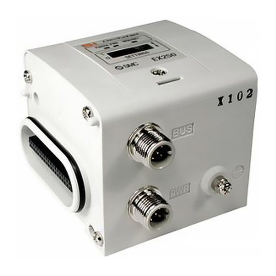
- Page 1 No.EX##-OMP0025 PRODUCT NAME SI unit for AS-Interface MODEL / Series / Product Number EX250-SAS#...
-
Page 2: Table Of Contents
Table of Contents Safety Instructions Product Outline Model Indication and How to Order Summary of Product elements Mounting and Installation Installation Wiring Setting Indication Connection between SI unit output and the solenoid valve Data bit Maintenance Troubleshooting Specifications Specifications Dimensions ... -
Page 3: Safety Instructions
Safety Instructions These safety instructions are intended to prevent hazardous situations and/or equipment damage. These instructions indicate the level of potential hazard with the labels of "Caution", "Warning" or "Danger". They are all important notes for safety and must be followed in addition to International ∗1) standards (ISO/IEC) and other safety regulations. - Page 4 Caution The product is provided for use in manufacturing industries. The product herein described is basically provided for peaceful use in manufacturing industries. If considering using the product in other industries, consult SMC beforehand and exchange specifications or a contract if necessary. If anything is unclear, contact your nearest sales branch.
- Page 5 Operator ♦This operation manual is intended for those who have knowledge of machinery using pneumatic equipment, and have sufficient knowledge of assembly, operation and maintenance of such equipment. Only those persons are allowed to perform assembly, operation and maintenance. ♦Read and understand this operation manual carefully before assembling, operating or providing maintenance to the product.
- Page 6 ■NOTE ○Follow the instructions given below when designing, selecting and handling the product. •The instructions on design and selection (installation, wiring, environment, adjustment, operation, described below must also be followed. maintenance, etc.) ∗Product specifications •When conformity to UL is necessary the SI unit must be used with a UL1310 Class2 power supply. •The SI unit is a approved product only if they have a mark on the body.
- Page 7 •Product handling ∗Installation •Do not drop, hit or apply excessive shock to the fieldbus system. Otherwise damage to the product can result, causing malfunction. •Tighten to the specified tightening torque. If the tightening torque is exceeded the mounting screws may be broken. IP67 protection cannot be guaranteed if the screws are not tightened to the specified torque.
- Page 8 •Mount the product in a place that is not exposed to vibration or impact. Otherwise failure or malfunction can result. •Do not use the product in an environment that is exposed to temperature cycle. Heat cycles other than ordinary changes in temperature can adversely affect the inside of the product. •Do not expose the product to direct sunlight.
-
Page 9: Product Outline
Product Outline System configuration This system connects input/output devices to AS-Interface with reduced wiring. AS-Interface communicates with the input/output devices via the SI unit. Input blocks, EX9 series output blocks and valve manifolds can be connected. ∗1: Refer to the operation manual EX250-IE1 / -IE2 / -IE3 for the input block specifications, and EX9-OET1 / -OET2 / -OEP1 / -OEP2 / -PE1 for the output block and power block specifications. -
Page 10: Model Indication And How To Order
Model Indication and How to Order EX250-S AS 3 Input / output and power supply PNP (negative common) / source, 8 inputs / 8 outputs, 2 power supply systems PNP (negative common) / source, 4 inputs / 4 outputs, 2 power supply systems PNP (negative common) / source, 8 inputs / 8 outputs, 1 power supply system PNP (negative common) / source, 4 inputs / 4 outputs, 1 power supply system Communication protocol... -
Page 11: Mounting And Installation
Mounting and Installation ■Installation The SI unit does not have mounting holes, so it cannot be installed alone. Make sure to connect the solenoid valve. When an input block is not required, connect the end plate directly to the SI unit. ○Installation example Dimensions when VQC2000 series solenoid valve manifold is connected are shown in the table below for reference. -
Page 12: Wiring
■Wiring ○The topology of an AS-i network The topology of an AS-i network can be connected as a tree, a line or point to point. The maximum total length of the cable must be 100 m. It is possible to extend the total length of the cable up to 300 m by using a repeater. -11- ... - Page 13 ○Wiring •EX250-SAS3/-SAS5 Communication connector: M12 4-pin, plug Description Function AS-i + AS−Interface line (+) (0 V) (Power supply for output equipment (-)) AS-i - AS−Interface line (-) (24 V) (Power supply for output equipment (+)) Power supply connector for output equipment: M12 4-pin, plug ∗...
- Page 14 •EX250-SAS7/-SAS9 Communication connector: M12 4-pin, plug Description Function AS−Interface line (+) AS-i + RESERVE RESERVE AS−Interface line (-) AS-i - RESERVE RESERVE •Connection example The M12 cable, AS-i standard cable and connector for T-branch are not supplied by SMC. Contact each manufacturer for the catalogue details etc. Wire the cable for AS-Interface line so that the total voltage drop is 3 V or less.
-
Page 15: Setting
Setting ○Address setting The AS-I cable line should be disconnected from the SI unit while setting the address. Open the cover and set the address using an AS-Interface address programming device and DC power jack cable etc. (PEPPERL + FUCHS: VAZ-PK-V1-Cinch, SIEMENS: 3RK1901-3HA00 etc.) The Address assignment range is 1 to 31. - Page 16 ○Address setting procedure via the AS-i line The following is the procedure for address setting of the master unit via the AS-i line with EX250-SAS3/-SAS7 (8 inputs / 8 outputs, and address connector – 2 pcs.). For setting the unit which occupies two slaves (EX250-SAS3/-SAS7), plug the cable jack into the address which is not to be set (ADDR2 when ADDR1 is set) to disconnect the address from the AS-i line.
-
Page 17: Indication
Indication Description LED condition EX250-SAS3/-SAS5 EX250-SAS7/-SAS9 Green LED is ON Indicates that the power supply for AS-Interface line is turned ON. Indicates that the power supply for Green LED is ON output equipment is turned ON. (LED is OFF at normal condition) ∗... -
Page 18: Connection Between Si Unit Output And The Solenoid Valve
Connection between SI unit output and the solenoid valve ○Standard wiring The outputs of the SI unit are assigned from the D side solenoid valve in the order 0, 1, 2 … etc. Refer to each solenoid valve’s catalogue for details. •Standard Address Mode (EX250-SAS3/-SAS7, EX250-IE3, Manifold standard wiring, Double solenoid wiring) ○Special wiring... -
Page 19: Data Bit
Data bit •SI unit input/output data bit Address Data bit EX250-SAS3/-SAS7 EX250-SAS5/-SAS9 IN0 / OUT0 IN0 / OUT0 IN1 / OUT1 IN1 / OUT1 ADDR1 IN2 / OUT2 IN2 / OUT2 IN3 / OUT3 IN3 / OUT3 IN4 / OUT4 IN5 / OUT5 ADDR2 IN6 / OUT6... -
Page 20: Maintenance
Maintenance Addition of input block •Remove the screws from the end plate to remove the plate. •Mount the additional tie rods (supplied with the input block). •Connect additional input block. •Re-mount the end plate that was removed, and tighten the screws to the specified tightening torque. (0.6 Nm) Replacing the SI unit •Remove the screws from the end plate and release the connection with the valve unit. ... -
Page 21: Troubleshooting
Troubleshooting Troubleshooting flow chart When any failure occurs with the SI unit, the following chart can be used to identify the cause of the failure. SI unit does not SI unit PWR LED Refer to fault operate normally. is OFF. - Page 22 Output block does not Check the state of Refer to fault operate correctly. the output block. No.9 Output block LED is OFF. Output block does not Refer to fault operate correctly. No.10 Output block LED is ON. Input device data Only the input Refer to fault signals above 32...
- Page 23 Troubleshooting Fault No.1 Problem Possible cause Investigation method Countermeasures Correct the AS-i cable connection. (Replace the AS-i line power supply Check the AS-i cable connections and check cable if it is broken.) wiring failure for broken wires. Correct the wiring of the AS-i SI unit PWR cable.
- Page 24 Fault No.5 Problem Possible cause Investigation method Countermeasures SI unit •EX250-SAS3/-SAS5 COM-ERR Over current to the Check the supply current to the input block Correct the supply current to LED red is power supply of •EX250-SAS7/-SAS9 within the specification flashing, input/output block Check the supply current to the input block, range.
- Page 25 Fault No.9 Problem Possible cause Investigation method Countermeasures Defective connection Confirm grounding to Check that the screws which connect the SI between the SI unit improve the anti-noise unit and output block are not loose. and output block performance of the SI unit. Polarity of the output Check that the output block polarity Use an output block polarity...
- Page 26 Fault No.12 Problem Possible cause Investigation method Countermeasures Tighten the screws while holding the SI unit and the Defective connection input block so that there is Check that the screws which connect the SI between the SI unit no gap between them. unit and input block are not loose.
-
Page 27: Specifications
Specifications ■Specifications General specification Item Specifications Ambient temperature 5 to 45 Ambient humidity 35 to 85%RH (no condensation) Storage temperature -20 to +60 Withstand voltage 500 VAC, 1 minute, Between whole external and FG Insulation resistance 500 VDC, 10 MΩ or more, Between whole external and FG Operating atmosphere No corrosive gas or dust Pollution degree... - Page 28 Electrical specifications Specifications Item EX250-SAS3 EX250-SAS5 EX250-SAS7 EX250-SAS9 ∗ 1 For communication Supplied by AS-Interface circuit. 26.5 to 31.6 VDC Power supply ∗ 2 voltage For output 24 VDC +10%/-5%, PELV ∗ 3 Internal current consumption (Unit) 100 mA or less 65 mA or less 100 mA or less 65 mA or less...
-
Page 29: Dimensions
■Dimensions ○EX250-SAS3/-SAS5 -28- No.EX##-OMP0025... - Page 30 ○EX250-SAS7/-SAS9 -29- No.EX##-OMP0025...
- Page 31 Revision history Note: Specifications are subject to change without prior notice and any obligation on the part of the manufacturer. © 2012 SMC Corporation All Rights Reserved No.EX##-OMP0025...
Need help?
Do you have a question about the EX250-SAS Series and is the answer not in the manual?
Questions and answers