SMC Networks EX510-GPR1 Operation Manual
Profibus dp compatible gw unit
Hide thumbs
Also See for EX510-GPR1:
- Operation manual (64 pages) ,
- Operation manual (13 pages) ,
- Manual (29 pages)
Advertisement
Quick Links
Fieldbus system
PROFIBUS DP Compatible GW unit
Operation Manual
EX510-GPR1
URL http://www.smcworld.com
Akihabara UDX 15F, 4-14-1, Sotokanda, Chiyoda-ku, Tokyo 101-0021, JAPAN
Phone: +81 3-5207-8249 Fax: +81 3-5298-5362
Note: Specifications are subject to change without prior notice and any obligation on the part of the manufacturer.
© 2009-2017 SMC Corporation All Rights Reserved
EX※※-OMH0024-C
Advertisement

Related Manuals for SMC Networks EX510-GPR1


Summary of Contents for SMC Networks EX510-GPR1
- Page 1 Fieldbus system PROFIBUS DP Compatible GW unit Operation Manual EX510-GPR1 URL http://www.smcworld.com Akihabara UDX 15F, 4-14-1, Sotokanda, Chiyoda-ku, Tokyo 101-0021, JAPAN Phone: +81 3-5207-8249 Fax: +81 3-5298-5362 Note: Specifications are subject to change without prior notice and any obligation on the part of the manufacturer.
-
Page 2: Table Of Contents
Table of Contents Thank you for purchasing an SMC fieldbus system EX510 series. Safety Instructions Please read this manual carefully before operating the product and make sure you understand its capabilities and limitations. Product Summary Please keep this manual handy for future reference. Name of Parts/ Accessories Dimensions Settings... -
Page 3: Safety Instructions
Safety Instructions The product and this manual contain essential information to Do not operate in an atmosphere containing flammable or protect users and others from possible injury and property explosive gases. damage and to ensure correct handling. Fire or an explosion can result. Please check that you fully understand the definition of the This product is not designed to be explosion proof. - Page 4 Safety Instructions (continued) Note •Take sufficient shielding measures when installing at the following place. •When conformity to UL is required, the SI unit should be used (1) A place where noise due to static electricity is generated with a UL1310 Class 2 power supply. (2) A place where electric field strength is high (3) A place where there is radioactive irradiation (4) A place near power line...
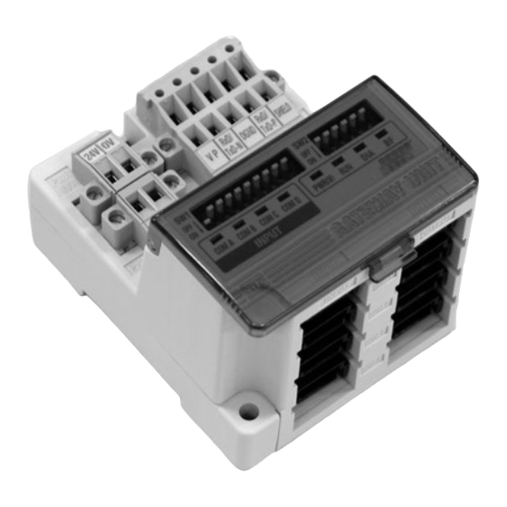
- Page 5 Accessory Power supply connector (2 pieces) Communication connector for PROFIBUS DP (1 piece) Parts Purpose 1 C ommunication s ocket (BUS) Connect to PROFIBUS DP line with an a ccessory connector for PROFIBUS DP(). C onnect a terminating resistor() to both end u nits of a transmission route. 2 P ower supply s ocket (PWR(V)) Supplying power for output instruments such as a s olenoid valve with an accessory connector().
-
Page 7: Specifications
Specifications Basic specifications Lower level bus 24 VDC Number of branches for 4 branches for input Rated voltage input/ output 4 branches for output Power supply for input and controlling GW: 24 VDC ±10% Power supply Communication protocol: Dedicated for SMC Power supply for output: 24 VDC+10%/-5% Communication type voltage... -
Page 8: Wiring
Wiring (continued) Branch wiring Press fitting Press the cover to the body with plier etc. The wiring between each unit should use branch cables, and be Confirmation connected with branch connectors. It is completed with a check on 4 latches SI unit and Input unit have 2 branch connectors for each. - Page 9 Wiring (continued) 390 Ω Data Line RxD/TxD-P 220 Ω Data Line RxD/TxD-N 390 Ω DGND (3) Refer to Drawing 4 about how to connect to the unit. Green Red Shield VP RxD/ RxD/ TxD-N DGND TxD-P SHIELD Green Red Shield...
- Page 10 Wiring (continued) Power supply wiring Connect power supply wiring to the two power supply 2-pin connectors. Power supply structure consists of 2 systems, but it can be used with both single power supply and separate power supply. Individual power supply for other units is not necessary. Make sure of connection with the designated pin.
-
Page 11: Display/ Switch Setting
Display/ Switch Setting (continued) Switch setting UNIT STATUS setting (switch No.8) Make sure that switch setting is performed with power supply turned off. The setting is as follows. Open the cover, and set DIP switch with a small flat blade The settings when shipped from plant is turned OFF, GW status screwdriver, etc. -
Page 12: Troubleshooting
Troubleshooting Display/ Switch Setting (continued) Input/Output setting (SW2) Remedy/ Disposal Input/output setting is performed with SW2. Number of input setting Number of output setting •Check the power for output (24 VDC) is supplied. •Check the branch cable is connected to SI unit. SoiijejKdKT d . - Page 13 Troubleshooting (continued) PROFIBUS DP compatible communication Item Remedy/ Disposal •Check the signal line from PLC is correctly connected. •Check the wiring and pin numbers. BF LED is •Check the address setting is correct. lights up •Check the connecting condition of the terminating resistor.
Need help?
Do you have a question about the EX510-GPR1 and is the answer not in the manual?
Questions and answers