SMC Networks EX500 Series Instruction Manual
Reduced wiring system devicenet compatible gw unit
Hide thumbs
Also See for EX500 Series:
- Technical instruction manual (40 pages) ,
- Instruction manual (22 pages)

Related Manuals for SMC Networks EX500 Series


Summary of Contents for SMC Networks EX500 Series
- Page 1 Reduced wiring system DeviceNet Compatible GW Unit Instruction Manual EX500-GDN1 URL http://www.smcworld.com...
-
Page 2: Table Of Contents
Contents Thank you for purchasing the SMC reduced wiring system EX500 series. SAFETY ......................2 Product Summary....................5 Please read this instruction manual carefully and understand the contents before EX500 use so that you can operate this unit safely and correctly. Part Names ....................6 Please keep this manual handy for future reference. -
Page 3: Safety
SAFETY The body of unit and this manual contain the essential information for the protection of users and others from possible injury and property damage and to ensure correct handling. Before performing maintenance: Turn off power supply. Please check that you fully understand the definitions of the following messages Stop air supply, exhaust compressed air in piping, and confirm the release ( symbols ) before going on to read the body of this manual, and always follow the to atmosphere. -
Page 4: Product Summary
Product Summary SAFETY ( continued ) Follow the instructions given below when handling your reduced wiring system. System configuration Otherwise a damage or failure to cause a malfunction can result. Operate the reduced wiring system at the specified voltage. DeviceNet Reserve space for maintenance. -
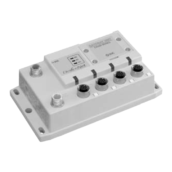
Page 5: Ex500 Part Names
EX500 Part Names Dimensions ( unit: mm ) EX500 body GATEWAY UNIT EX500 SERIES 24VDC COM A COM B COM C COM D Name Application Communication Connect with DeviceNet line. ( Note 1 ) connector Power supply connector Supply power for output devices such as solenoid... -
Page 6: Specification
Total extended length of trunk line and drop lines depends on the date rate and the Range of power Power supply for input and controlling GW/SI: DC24V thickness of communication cable. The connection type for EX500 series is supply voltage Power supply for output: DC24V+10%/-5% ( Voltage drop T-branch only. -
Page 7: Wiring
Wiring Specification ( continued ) Cable specification Internal circuit DRAIN Thick cable Thin cable Item RD - Signal Power Signal Power CAN H TD - COM A Conductor’s 0.82mm 1.65mm 0.20mm 0.33mm CAN L +24V cross-section area +24V DC-DC Color Blue, white Red, black Blue, white... - Page 8 Wiring ( continued ) Communication wiring Power supply wiring Connect the cable with DeviceNet communication connector to the communication Connect the power supply connector cable to the power supply connector of GW unit. connector of GW unit. There are two types of cables different in connector shape ---- straight type and angle type.
- Page 9 Wiring ( continued ) Separate wiring for power supply for solenoid valves/output and Branch wiring ( wiring to communication ports ) for input and control of GW/SI For wiring with solenoid valves or input devices, connect the branch cable with M12 connector to communication ports A - D.
- Page 10 Wiring (continued ) For GW unit – Manifold valve – Input unit manifold configuration For GW unit – Input unit manifold configuration Two communication connectors in SI unit and one communication connector in Input To the communication connector of Input unit, connect the branch cable with M12 unit are installed respectively.
-
Page 11: Display/Switch Setting
Open the station number switch protective cover and set the switches with a sharp-pointed watchmakers screwdriver etc. GATEWAY UNIT EX500 SERIES NOTE 1. Be sure to turn off the power before setting the switches. 2. Be sure to set these switches before use. -
Page 12: Si Unit
SI Unit Part Names Dimensions ( unit: mm ) The SI unit is the unit to communicate with GW unit in combination with manifold valve. 1. SI unit for SV series valves ( EX500-S 01 ) It can be used with SV series valves and VQC series valves. In addition, this unit is able to operate solenoid valves, relays. -
Page 13: Mounting/Wiring
Mounting/Wiring Specification The mounting and removing methods of SI unit are as shown below. 1. SI unit for SV series valve ( EX500-S 01 ) Item Specification Connected block Solenoid valve ( single, double ) Relay output module ( 1-point output, 2- point output ) Connected block Max. -
Page 14: Display
Display Input Unit Manifold Part Names The Input unit manifold consists of Input unit, input block (s), end block and DIN rail. SI unit for SV series valves ( EX500-S 01 ) The input block up to 8 can be connected ( 16 points ). Any combination of input blocks ( for M8 connector, M12 connector and 8-point- integrated type ) is acceptable. -
Page 15: Dimensions
Dimensions ( unit: mm ) When only input blocks for M8 connector are connected When only input blocks for M12 connector are connected DIN Rail DIN Rail (L4) L2 ( Rail mounting pitch: 12.5 ) (L4) L2 ( Rail mounting pitch: 12.5 ) Stations L1 [mm]: Rail length 110.5... -
Page 16: Specification
Specification Wiring Specifications for Input unit Branch wiring For wiring method, refer to subsection "Wiring" ( page 11 ) of section "EX500" in this Item Specification manual. To input devices such as sensor, the power is supplied through the branch Connected block wiring ( branch cable with M12 connector ). -
Page 17: Display
( EX9-PE1 ) connected with external power supply. As the low-wattage-load type is powered from SI unit, the wattage of load is limited to 1.0W ( Note1 ). For a load up to 12W, use the power block and the high-wattage-load type. Note1: When connected with EX500 series. 1. EX9-OET1/EX9-OET2/EX9-OEP1/EX9-OEP2 VQC series... -
Page 18: Dimensions
Mounting EX9 Series General Purpose Output Block Part Names (continued ) 2. EX9-PE1 The mounting and removing methods of each SI unit are as shown below. Supply/exhaust block assembly, end plate R, power block, or other VQC series EX9 series general purpose output block SI unit for general purpose output block... -
Page 19: Wiring
Wiring Output wiring Power supply wiring Connect output devices to the output connectors. When combining EX9-OEP1 ( or EX9-OEP2 ) and EX9-PE1 and using external power supply, connect the power supply to the power input connector of EX9-PE1. EX9-OET1/EX9-OET2/EX9-OEP1/EX9-OEP2 output connectors When selecting power supply, refer to "Handling precautions"... -
Page 20: Specification
Specification Display 1. EX9-OET1/EX9-OET2/ EX9-OEP1/EX9-OEP2 Settings for display Item Specification 1. EX9-OET1/EX9-OET2/EX9-OEP1/EX9-OEP2 Model No. EX9-OET1 EX9-OET2 EX9-OEP1 EX9-OEP2 No. of output 2 points/unit points Display Description Output P-ch MOS-FET N-ch MOS-FET P-ch MOS-FET N-ch MOS-FET Lights on: Output ( OUT 0 ) is ON. method ( open drain ) ( open drain ) - Page 21 Option Cable with DeviceNet communication connector Waterproof cap For details, refer to subsection "Wiring" ( page 11 ) in section "EX500" in this manual. Mounted on unused ports of GW unit, input block, power block and output block. The proper use of this waterproof cap can achieve IP65 Enclosure. ( The waterproof caps How to order are delivered together with each input block as accessories.
-
Page 22: Troubleshooting
Troubleshooting Overall system DeviceNet compatible communication Item Solution/Corrective action Item Solution/Corrective action Solenoid valve Check the power for solenoid valves/output ( DC24V ) MS LED status Check the signal line from PLC is doesn't work is supplied. Normal status: Lit in green connected.
Need help?
Do you have a question about the EX500 Series and is the answer not in the manual?
Questions and answers