
Related Manuals for SMC Networks EX250-SDN1


Summary of Contents for SMC Networks EX250-SDN1
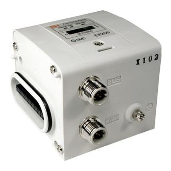
- Page 1 No.EX※※-OME0003-H PRODUCT NAME ® SI unit for DeviceNet MODEL / Series / Product Number EX250-SDN1 EX250-SDN1-X102...
-
Page 2: Table Of Contents
Table of Contents Safety Instructions Product Summary Model indication and How to Order Summary of Product parts Mounting and Installation Installation Wiring Indication and Settings ® DeviceNet objects Maintenance Troubleshooting Specification Specifications Dimensions Option No.EX※※-OME0003-H... -
Page 3: Safety Instructions
Safety Instructions These safety instructions are intended to prevent hazardous situations and/or equipment damage. These instructions indicate the level of potential hazard with the labels of "Caution", "Warning" or "Danger". They are all important notes for safety and must be followed in addition to International Standards (ISO/IEC) , and other safety regulations. - Page 4 Safety Instructions Caution 1.The product is provided for use in manufacturing industries. The product herein described is basically provided for peaceful use in manufacturing industries. If considering using the product in other industries, consult SMC beforehand and exchange specifications or a contract if necessary. If anything is unclear, contact your nearest sales branch.
- Page 5 Operator ♦This operation manual is intended for those who have knowledge of machinery using pneumatic equipment, and have sufficient knowledge of assembly, operation and maintenance of such equipment. Only those persons are allowed to perform assembly, operation and maintenance. ♦Read and understand this operation manual carefully before assembling, operating or providing maintenance to the product.
- Page 6 Caution ■After maintenance is complete, perform appropriate functional inspections. Stop operation if the equipment does not function properly. Safety cannot be assured in the case of unexpected malfunction. ■Provide grounding to assure the noise resistance of the Fieldbus system. Individual grounding should be provided close to the product with a short cable. ■NOTE ○Follow the instructions given below when designing, selecting and handling the product.
- Page 7 •Product handling ∗Installation •Do not drop, hit or apply excessive shock to the fieldbus system. Otherwise damage to the product can result, causing malfunction. •Tighten to the specified tightening torque. If the tightening torque is exceeded the mounting screws may be broken. IP67 protection cannot be guaranteed if the screws are not tightened to the specified torque.
- Page 8 •Mount the product in a place that is not exposed to vibration or impact. Otherwise failure or malfunction can result. •Do not use the product in an environment that is exposed to temperature cycle. Heat cycles other than ordinary changes in temperature can adversely affect the inside of the product. •Do not expose the product to direct sunlight.
-
Page 9: Product Summary
Product Summary System configuration ® ® This system connects input/output devices to DeviceNet with reduced wiring. DeviceNet communicates with the input/output devices via the SI unit. Input block and output block/valve manifolds of the EX9 series can be connected to 32 input points or 32 ∗... -
Page 10: Model Indication And How To Order
Model indication and How to Order Summary of Product parts Element Description ∗1 ® Communication connector Sends or receives communication signals via DeviceNet line. ∗1 Power supply connector Supplies power to the solenoid valve, output block, SI unit and input block. Input block connector Connects the input block Output block connector... -
Page 11: Mounting And Installation
Mounting and Installation ■Installation The SI unit does not have mounting holes, so it cannot be installed alone. Make sure to connect the valve manifold. When an input block is not required, connect the end plate directly to the SI unit. ○Installation example N•m 45 55.5... -
Page 12: Wiring
■Wiring Connect the appropriate cable connector to the connector on the SI unit as shown below. ○Communication wiring ® The DeviceNet communication connector specifications are shown below. M12 5-pin plug A-code Pin No. Signal name DRAIN CAN_H CAN_L Note Wiring should be carried out with the power supply turned off. Do not route the communication cable near to high voltage cables such as a power cable or high current electrical cable. - Page 13 ® Pin Layout and Wiring of DeviceNet Communication Connector Cable Connect the M12 connector cable (socket) to the communication connector. Pin No. Cable colour: Signal DRAIN Red: V+ Black: V- White: CAN_H Blue: CAN_L -12- No.EX※※-OME0003-H...
- Page 14 ○DeviceNet ® Media Topology ® A shielded twisted pair cable for DeviceNet should be used. The maximum cable length depends on the communication speed and the cable type used. <Communication speed [kbps] and max. bus cable length> Maximum cable length for network Communication speed Drop line length Cumulative Drop...
- Page 15 ○Power supply wiring Connect a power supply cable connector to the power supply connector on the SI unit. Refer to "Safety Instructions" on page of this operation manual for the selection of the power supply. ○Power supply connector (M12 5-pin B-code (reverse)) Pin No.
- Page 16 Pin Layout and Wiring of Power Supply Connector Cable Pin No. Cable color: Signal Brown: SV24 V White: SV0 V Blue: SW24 V Black: SW0 V Grey: Ground ○FE connection Note Connect the ground terminal to the ground. Resistance to the ground should be 100 ohms or less. -15- No.EX※※-OME0003-H...
- Page 17 Within the SI unit there are separate power supply lines for the solenoid valves (SV power supply) and for the input block (SW power supply). Supply 24 V DC to each of them. Power can be supplied from a single power supply or from separate power supplies.
-
Page 18: Indication And Settings
MAC ID duplication error or BUS OFF error (serious communication error) ∗: EX250-SDN1 disconnects the I/O connection when the solenoid valve power supply decreases or when the input block fuse is detected to be broken (EX250-SDN1-X102 does not disconnect the I/O connection). - Page 19 ○Switch setting Open the protective cover, and set the switches with a small flat blade screwdriver. Note 1. The power supply should be off while setting the switches. 2. Be sure to set the switches before use. 3. After setting the switches, close the switch cover and tighten the screw to the specified torque. (Tightening torque: 0.6 N•m) Address setting -18-...
- Page 20 DIP switch position Caution •The default settings are MAC ID 63 and communication speed 125 kbps (Hardware setting mode). •The MAC ID and communication speed set in SW setting mode are maintained even when the SI unit power supply is turned off. When the power supply is applied in HW setting mode, the MAC ID and communication speed set in SW mode are deleted, and the MAC ID and communication speed set by the switches are memorized.
- Page 21 ○Settings via DeviceNet ® network ® It is possible to set the node address (MAC_ID), DeviceNet communication speed and output condition when a communication error is generated, via the network, in accordance with the procedure below. •Node address setting, communication speed setting 1) Turn SW1-10 on the SI unit ON (SW mode).
- Page 22 Normally: Displays "1"). DI_CHK: Detects broken fuse in the input block (When fuse is broken: Displays "0", Normally: Displays "1"). •EX250-SDN1 disconnects the I/O connection when either of the SOLV or DI_CHK is abnormal. (EX250-SDN1-X102 does not disconnect the I/O connection).
- Page 23 ○Output No. assignment Combinations of output data and valve manifold Output data ∗: Output No. starts from 0, and will be assigned to the valves in order from the SI unit mounted side. ∗: Manifold wiring is double wired as standard ("double wiring specification"), and the output numbers are assigned in order from A side to B side.
-
Page 24: Devicenet Objects
1-2. Class common service Service code Service name 1-3. Instance attribute Access rule Description Value Vender ID Device Type 1Bh (27) EX250-SDN1: 961h (2401) Product Code EX250-SDN1-X102: 964h (2404) Revision Per unit Status Serial Number Per unit Product Name Valve manifold SIU -23- No.EX※※-OME0003-H... - Page 25 1-4. Instance common service Service code Service name Reset Get_Attribute_Single 1-5. Specific service None. 2. Message Router Object (Class ID: 02h) 2-1. Class attribute Access rule Description Value 2-2. Class common service Service code Description 2-3. Instance attribute Access rule Description Value 2-4 Instance common service...
- Page 26 Data ∗1: If the instance type is input, the access rule will be Get. 4-4. Discrete Input Assembly instance Type Description No. of bytes Product model Input 32 Discrete input Points EX250-SDN1 Input 32 Discrete input Points EX250-SDN1-X102 -25- No.EX※※-OME0003-H...
- Page 27 The data format is shown below. Data Byte offset bit7 bit0 IN15 IN14 IN13 IN12 IN11 IN10 IN23 IN22 IN21 IN20 IN19 IN18 IN17 IN16 IN31 IN30 IN29 IN28 IN27 IN26 IN25 IN24 IN15 IN14 IN13 IN12 IN11 IN10 IN23 IN22 IN21 IN20...
- Page 28 ® 5. DeviceNet Connection Object (Class ID: 05h) 5-1. Class attribute Access rule Description Value 5-2. Class common service Service code Service name 5-3. Instance attribute1 (Explicit message) Access rule Description Value State Instance_type TransportClass_trigger ® DeviceNet _produced_connection_id ® DeviceNet _consumed_connection_id ®...
- Page 29 Access rule Description Value State Instance_type TransportClass_trigger ® DeviceNet _produced_connection_id ® DeviceNet _consumed_connection_id ® DeviceNet _initial_comm_characteristics 04h: EX250-SDN1 Produced_connection_size 06h: EX250-SDN1-X102 Consumed_connection_size Get/Set Expected_packet_rate Get/Set Watchdog_timeout_action Produced_connection_path_length 20h 04h 24h □□h 30h 03h Produced_connection_path 11: EX250-SDN1 12: EX250-SDN1-X102 Consumed_connection_path_length Consumed_connection_path...
- Page 30 6. Discrete Input Point Object (Class ID: 08h) 6-1 Class attribute Access rule Description Data type Value Revision UINT 6-2. Class common service Service code Service name Get_Attribute_Single 6-3. Instance attribute Access rule Description Data type Value 0: OFF Value BooL 1: ON 0: Input block fuse is normal...
- Page 31 7. Discrete Output Point Object (Class ID 09h) 7-1. Class attribute Access rule Description Value 7-2. Class common service Service code Service name 7-3. Instance attribute Access rule Description Value 0: OFF Get/Set Value 1: ON 0: Normal Status 1: Valve power supply failure 0: Fault set value ∗1 Get/Set...
- Page 32 8. Parameter Object (Class ID: 0Fh) 8-1. Class attribute Access rule Description Value Max Instance Parameter Class Descriptor Configuration Assembly Instance 8-2. Class common service Service code Service name Get_Attribute_Single 8-3. Instance attribute 1: SOLV Status Access rule Description Value 1: Valve power supply voltage is normal Parameter Value 0: Valve power supply voltage is abnormal...
- Page 33 8-6. Instance attribute 6: HOLD/Clear (Delete) Access rule Description Value 0: Switch setting valid Parameter Value 1: Fault action valid Link Path Size Link Path 20h 64h 24h 01h 30h 69h Descriptor Data Type Data Size 8-7. Instance common service Service code Service name Get_Attribute_Single...
-
Page 34: Maintenance
Maintenance Replacing the SI unit •Remove the screws from the end plate and release the connection with the valve unit. •Replace the SI unit (There is no need to remove the tie rod). Re-mount the end plate that was removed, and tighten the screws to the specified tightening torque. (0.6 N•m) Precautions for maintenance (1) Turn off the power supply completely. -
Page 35: Troubleshooting
Troubleshooting Troubleshooting flow chart When any failure occurs with the SI unit, the following chart can be used to identify the cause of the failure. SI unit does not SI unit PWR LED Refer to fault is OFF. operate normally. No.1 The “PWR(V)”... - Page 36 Output block does not Check the state of Refer to fault operate correctly. the output. No.10 Output block LED is OFF. Output block does not Refer to fault operate correctly. No.11 Output block LED is ON. Input device data Only the input Refer to fault cannot be signals above 32...
- Page 37 ∗: PWR (V) LED is OFF regardless of the solenoid valve power supply when the DeviceNet ® communication power supply is not supplied (when the SI unit PWR_LED is OFF). EX250-SDN1 disconnects the I/O connection when the solenoid valve power supply decreases. EX250-SDN1-X102 does not disconnect the I/O connection. Fault No.3 Problem...
- Page 38 Fault No.4 Problem Possible cause Investigation method Countermeasures MAC ID duplication Check that there is no MAC ID duplication Correct the MAC ID settings. error between the master and slave. Check that the length of the communication cable is suitable for the communication Correct the wiring and speed, check for terminators at both ends, settings.
- Page 39 Fault No.6 Problem Possible cause Investigation method Countermeasures ® Tighten the DeviceNet cable connection. (If the Incorrect wiring of the cable has a broken wire, ® power supply for Check the DeviceNet cable connections and SI unit replace the cable). ®...
- Page 40 Fault No.10 Problem Possible cause Investigation method Countermeasures Defective connection Confirm grounding to Check that the screws which connect the SI between the SI unit improve the anti-noise unit and output block are not loose. and output block performance of the SI unit. Check that the output block polarity specification and output polarity of the SI unit Polarity of the output...
- Page 41 Check that the input block is operating Input block failure Replace the input block. correctly. ∗1: EX250-SDN1 disconnects the I/O connection when fuse of the input block breaks. EX250-SDN1-X102 does not disconnect the I/O connection. Fault No.14 Problem Possible cause...
- Page 42 Fault No.15 Problem Possible cause Investigation method Countermeasures Tighten the screws while holding the SI unit and the Defective connection Check that the screws which connect the SI input block so that there is between the SI unit Input block unit and input block are not loose.
-
Page 43: Specification
0.3 VDC or less Communication specification Specifications Item EX250-SDN1 EX250-SDN1-X102 0 to 63 (MAC ID information is maintained even when the power supply MAC ID set range is cut if it is set either by the DIP switch or via communication network). -
Page 44: Dimensions
■Dimensions ○EX250-SDN1/EX250-SDN1-X102 -43- No.EX※※-OME0003-H... - Page 45 Option ® 1. DeviceNet communication connector cable φ6.7 Cable O.D. 0.33 mm Power line AWG22 Nominal cross section area 0.2 mm Signal line AWG24 Power line 1.4 mm Wire diameter Signal line 2.05 mm Minimum bending radius 67 mm (fixed) ®...
- Page 46 4. Power supply connector cable φ6.6 Cable O.D. Nominal cross 0.3 mm /AWG22 section area Wire diameter 1.65 mm Minimum bending 40 mm (fixed) radius 5. Spare fuse (for input block) 6. Electrical entry connector cable φ6.6 Cable O.D. Nominal cross 0.3 mm /AWG22 section area...
- Page 47 8. Input block relay connector cable M12 connector φ4.7 Cable O.D. Minimum bending 47 mm (fixed) radius M8 connector φ4.4 Cable O.D. Minimum bending 44 mm (fixed) radius 9. Input block assembly type connector -46- No.EX※※-OME0003-H...
- Page 48 10. End plate (on the input block side) EX250-EA1 EX250-EA2 11. End plate R (on the output block side) EX9-EA03 EX9-EA04 -47- No.EX※※-OME0003-H...
- Page 49 12. Waterproof cap Mount this to the unused ports of the input block, output block and power block. Proper use of the waterproof cap enables the enclosure to achieve IP67 specification. (The power block is provided with the product.) Note Tighten the waterproof caps to the tightening torque specified.
- Page 50 Revision history C: All revised contents. D: Modified errors in text. E: Limited warranty and Disclaimer are added. F: Contents are added. [July 2017] G: Contents are added. [January 2021] H: Contents revised in several places. [December 2021] 4-14-1, Sotokanda, Chiyoda-ku, Tokyo 101-0021 JAPAN Tel: + 81 3 5207 8249 Fax: +81 3 5298 5362 https://www.smcworld.com Note: Specifications are subject to change without prior notice and any obligation on the part of the manufacturer.
Need help?
Do you have a question about the EX250-SDN1 and is the answer not in the manual?
Questions and answers