
Related Manuals for SMC Networks EX260-PPN1


Summary of Contents for SMC Networks EX260-PPN1
- Page 1 Doc. No. DOC1084511 PRODUCT NAME Fieldbus system PROFINET compatible SI Unit MODEL / Series / Product Number EX260-PPN1...
-
Page 2: Table Of Contents
Contents Safety Instructions.................... 1. Product summary....................1.1. Features........................... 1.2. Parts and description........................2. Installation..................... 2.1. Mounting............................2.2. Wiring............................3. Configuration....................3.1. GSD file, Head module........................3.2. Module............................3.3. Submodule............................ 3.4. FactoryReset..........................3.5. Configuration example........................4. Parameters....................4.1. Module parameters for Head module.................... 4.2. -
Page 3: Safety Instructions
Safety Instructions These safety instructions are intended to prevent hazardous situations and/or equipment damage. These instructions indicate the level of potential hazard with the labels of “Caution,” “Warning” or “Danger.” They are all important notes for safety and must be followed in addition to International Standards (ISO/IEC) , and other safety regulations. -
Page 4: Limited Warranty And Disclaimer/Compliance Requirements
Safety Instructions Caution We develop, design, and manufacture our products to be used for automatic control equipment, and provide them for peaceful use in manufacturing business. Use in non-manufacturing business is not covered. Products we manufacture and sell cannot be used for the purpose of transactions or certification specified in the Measurement Act. - Page 5 Operator This operation manual is intended for those who have knowledge of machinery using pneumatic equipment, and have sufficient knowledge of assembly, operation and maintenance of such equipment. Only those persons are allowed to perform assembly, operation and maintenance. Read and understand this operation manual carefully before assembling, operating or providing maintenance to the product.
-
Page 6: Product Specifications
Caution ■When handling or assembling or replacing the unit, pay attention to the following: •Do not touch the sharp edges when overseeing the unit. •The unit joints are tightly bound with gaskets, so do not hit your hands when replacing the unit. •Do not put your fingers between them when joining the units. - Page 7 •Product handling Installation •Do not drop, hit or apply excessive shock to the fieldbus system. Otherwise, damage to the product can result, causing malfunction. •Tighten to the specified tightening torque. If the tightening torque is exceeded the mounting screws may be broken. If the screws are not tightened to the specified torque, the dustproof and waterproof performance (protection class) of the product is not guaranteed.
-
Page 8: Maintenance
•Mount the product in a place that is not exposed to excessive vibration or impact. Otherwise, failure or malfunction can result. •Do not use the product in an environment that is exposed to temperature cycle. Heat cycles other than ordinary changes in temperature can adversely affect the inside of the product. •Do not expose the product to direct sunlight. - Page 9 Fieldbus System/ Industrial IoT Cybersecurity In recent years, factories have introduced industrial IoT, building up complex networks of production machines. These systems maybe subject to a new threat, cyberattack. To protect the industrial IoT from cyberattacks, it is important to take multiple measures (multi-layer protection) for IoT devices, networks and clouds. For this purpose, SMC recommends that the following measures are always taken into consideration.
-
Page 10: Product Summary
1. Product summary 1.1. Features The SI (Serial Interface) Unit represents a PROFINET IO-device for SMC pneumatic valves. The SI Unit controls a valve manifold integrated with ejector system has the following properties. For valve manifold, refer to the instruction manual for the valve manifold integrated with ejector system. The valve manifold part number is JSY1000-E. -
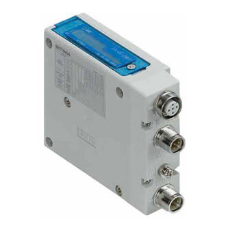
Page 11: Parts And Description
1.2. Parts and description Item Description Communication connector 2 (BUS OUT / Port 2) PROFINET connection. (M12 4-pin socket, D-coded) Refer to Section 2.2.1. Communication connector 1 (BUS IN / Port 1) Power supply for control/sensors and valves.(M12 4-pin plug, A-coded) 3 Power connector Refer to Section... -
Page 12: Installation
2. Installation 2.1. Mounting 2.1.1. Valve manifold connection Connect the valve manifold with the 2 screws on the SI Unit. (Hexagonal socket wrench size 2.5 mm) Note Tighten the screws while holding the SI Unit and the valve manifold so that there is no gap between them. ... -
Page 13: Wiring
2.2. Wiring Connect the PROFINET communication cables, the power cables and the FE cable. Select the appropriate cables to mate with the connectors and terminal mounted on the SI Unit, refer to Section 1. M12 4-pin socket, D-coded, PROFINET communication connector BUS OUT (Port 2), Port type : MDI-X 2. - Page 14 Note When the auto crossover function (Auto MDI-X) is disabled, the correct network cable must be selected, refer to Fig 2-5. The Auto crossover function shall be capable of switching over their twisted pair ports automatically between MDI and MDI-X pin assignment. The Auto crossover function need to be disabled when using the FSU (Fast Start Up) function.
- Page 15 2.2.2. Power connector PWR : M12 4-pin plug, A-coded Pin No. Designation Content 24 V (PWR(V)) +24 V for valves 0 V (PWR(V)) 0 V for valves 24 V (PWR) +24 V for control/sensors 0 V (PWR) 0 V for control/sensors Fig 2-6.
-
Page 16: Configuration
The GSD file contains one type of head module. The names of GSD files, symbol files and head module are as follows. Table 3-1. GSD file, Head module Item Name GSD file GSDML-V2.43-SMC-EX260-PPN1-********.xml Symbol file GSDML-0083-0030-EX260.bmp Head module EX260-PPN1 3.2. Module Table 3-2. -
Page 17: Factoryreset
3.4. FactoryReset When the FactoryReset / ResetToFactory command is received, the PROFINET IO communication parameters etc. are initialised and the SI Unit is restarted. Table 3-4 shows examples of data initialised by FactoryReset and data not initialised. Table 3-4. Example of data to be initialised, data not to be initialised Data to be initialized Default value Data not to be initialized... -
Page 18: Configuration Steps
Configuration steps After installing the GSD file, select the head module EX260-PPN1 and add it to the configuration. (The Valve output module is automatically added to the 24 Valves output Slot.) Match the Device name on the configuration with that of the actual SI unit. - Page 19 Contents of configuration example / (Sub) Slot name Slot No. setting byte byte Optional setting EX260-PPN1 SI Unit head module Unit diagnosis SI Unit diagnosis SI Unit overall diagnosis : required Valve output 24 Valves output Output parameters and valve output instructions...
-
Page 20: Parameters
4. Parameters 4.1. Module parameters for Head module Table 4-1. Energy mode Item Set value Default Description Set the valve output operation after the start of Energy saving mode Proceed Valve supply (PROFIenergy). Shut down, and output Proceed : Valve output as instructed by the IO controller. Shut down, Force to OFF value at pause... -
Page 21: Module Parameters For Extended Function Module
4.3. Module parameters for Extended function module Parameters related to sensor extension functions such as energy saving function and valve protection function are set for each sensor. For vacuum / pressure state and example of energy saving operation, refer to Section Table 4-4. - Page 22 Table 4-5. Examples of manifold structure and option settings Built-in Optional setting Product name Product number sensor (1) SI Unit EX260-PPN1 SI Unit overall diagnosis : required Individual valve short circuit - Valve manifold JJ5SY1-E10SFN-06B-4AX-C4 diagnosis : required (2) 2-position 3-port (single) valve...
- Page 23 Select Module parameters : Sensor extended parameter from the properties of the Extended function submodule of Pressure sensor No.4 and set the parameters. The operation related to sensor No. 4 when set as described above is as follows. Table 4-6. Examples of sensor extended function parameter settings and their operation. Extended function Parameter set value Operation...
-
Page 24: Process Data
5. Process data 5.1. Input process data for Unit diagnosis module Table 5-1. Input process data for Unit diagnosis module byte Content Description 0 : No valves have a short circuit Valve short circuit 1 : At least one valve has a short circuit 0 : No sensor connection error Sensor connection error 1 : The number of connected sensors is less than the module... -
Page 25: Input Process Data For Valve Diagnosis Module
5.3. Input process data for Valve diagnosis module Table 5-3. Input process data for Valve diagnosis module byte Content Description Valve short circuit state of OUT0 Valve short circuit state of OUT7 Valve short circuit state of OUT8 0 : Valve doesn't have a short circuit 1 : Valve has a short circuit Valve short circuit state of OUT15 Valve short circuit state of OUT16... -
Page 26: Example Of Energy Saving Operation For Ejector
6. Example of energy saving operation for ejector Energy saving function for ejector -> OUT0:Supply valve, OUT1:Release valve Supply valve type -> N.C. (Refer to Section 4.3) Positive pressure(700kPa) Threshold of Pressure P3 Threshold of Pressure P4 Atmospheric Time pressure Threshold of Vacuum P1 Energy saving... -
Page 27: Recorddata
7. RecordData The following shows User specific RecordData. In the Access column, "R" shows Read (read only), "W" indicates Write (write only) and "R/W" indicates Read/Write (both read and write possible). The RecordData of R/W is assigned to Module parameters by the GSD file, refer to Section Table 7-1. - Page 28 7.1.3. Output counter limit value Table 7-4. Output counter limit value Index Slot No. Sub slot No. byte Content Description / Value 0...3 Output counter limit value of OUT0 4...7 Output counter limit value of OUT1 0...4,294,967,295[dec] 0x0004 (Default value : 4,294,967,295) 92...95 Output counter limit value of OUT23 7.1.4.
-
Page 29: Other Recorddata
7.2. Other RecordData 7.2.1. Output counter Table 7-6. Output counter Index Slot No. Sub slot No. byte Content Description / Value 0...3 Output counter OUT0 4...7 Output counter OUT1 Read the valve output count number. (ON count) 0x0006 Read range : 0...4,294,967,295[dec] 92...95 Output counter OUT23 7.2.2. - Page 30 7.2.3. Sensor individual zero offset Table 7-9. Sensor individual zero offset Index Slot No. Sub slot No. byte Content Description / Value 0,1 Zero offset of sensor No.1 2...7 Unused 0,1 Zero offset of sensor No.2 Adjust pressure value to 0 kPa at 2...7 Unused atmospheric pressure.
-
Page 31: Led Indication / Alarm
8. LED indication / Alarm 8.1. LED indication Indication Description No diagnostic information One of the following may have occurred. (Fault alarm) Valve has a short circuit. Red ON The number of connected sensors is less than the module setting or sensor has a communication error. -
Page 32: Alarm
(sub)module Short circuit Valve output 0...23 Fault Red ON Pressure value Sensor connection error 4..8 Extended function Voltage drop of PWR EX260-PPN1 (Head) Output count over Valve output 0...23 Maintenance Green required flashing Valve protection Extended function 4...8 Energy saving parameter error Extended function 4...8... -
Page 33: Specification
9. Specification 9.1. Specifications Table 9-1. Specifications Item Specification General IP67 (when fully installed to valve manifold) (complies with IEC60529) Protection class CE / UKCA Marking, UL(CSA) Standards Dimensions (W x L x H) 34.2 x 102.4 x 76.5 Housing material Weight 200 g Withstand voltage... -
Page 34: Dimensions
9.2. Dimensions Fig 9-1. Dimensions of the SI Unit -34- No. DOC1084511... -
Page 35: Block Diagram
M12, 4-pins, plug, A-coded ① 24 V (PWR(V)) Power ② 0 V (PWR(V)) Output circuit connector ③ 24 V (PWR) (PNP) (PWR) ④ 0 V (PWR) SI Unit Valve Manifold Integrated with Ejector System (EX260-PPN1) Fig 9-2. Block diagram -35- No. DOC1084511... -
Page 36: Accessories
10. Accessories 10.1. Accessories for communication connector 10.1.1. Cable with both-sided connector (M12 – RJ45) Part number : EX9-AC 01 0EN-PSRJ Cable length (L) 1,000 mm 2,000 mm 3,000 mm 5,000 mm 10,000 mm Item Specification Pin No. (M12) Pin No. (RJ45) Cable colour : Signal M12 straight ... - Page 37 10.1.2. Cable with both-sided connector (M12 – M12, Straight) Part number : EX9-AC 005 EN-PSPS Cable length (L) 500 mm 1,000 mm 2,000 mm 3,000 mm 5,000 mm 10,000 mm Item Specification Pin No. Cable colour : Signal M12 straight M12 straight Connector Yellow : TD+ Cable O.D.
- Page 38 10.1.3. Cable with both-sided connector (M12 – M12, Angle) Part number : EX9-AC 005 EN-PAPA Cable length (L) 500 mm 1,000 mm 2,000 mm 3,000 mm 5,000 mm 10,000 mm Item Specification Pin No. Cable colour : Signal M12 angle M12 angle Connector Yellow : TD+ Cable O.D.
-
Page 39: Accessories For Power Connector
10.2. Accessories for power connector 10.2.1. Cable with one-sided connector Part number : EX500-AP0 1 0- S Connector specification Straight Angle Cable length (L) 1,000 mm 5,000 mm EX500-AP0x0-S EX500-AP0x0-A Item Specification Pin No. Cable colour : Signal Cable O.D. φ6 mm Brown : 24 VDC (for control/sensors) Electric wire cross section... - Page 40 10.2.2. 10.2.1. Cable with one-sided connector (SPEEDCON) Part number : PCA-140180 4 Cable length (L) 1,500 mm 3,000 mm 5,000 mm Item Specification Pin No. Cable colour : Signal Brown : 24 VDC (for control/sensors) M12 straight Connector (SPEEDCON) White : 24 VDC (for valves) Cable O.D.
-
Page 41: Troubleshooting
11. Troubleshooting The state of the SI Unit is indicated by the LED indication. If a problem occurs on the SI Unit, you can use the following chart to troubleshoot. Also refer to the online diagnostics via the software of the IO controller to help identify the problem. 11.1. -
Page 42: Troubleshooting Tables
11.2. Troubleshooting Tables Table 11-1. Troubleshooting "PWR LED is OFF or green flashing" Probable causes Checking methods and measures 状態 Check the power supply wiring for control/sensors. Incorrect wiring. Check the pin No. and wiring conditions of the power connector, refer to Section 2.2.2. - Page 43 Table 11-4. Troubleshooting "BF LED is red ON" Probable causes Checking methods and measures 状態 The SI Unit is connected to a network of some kind, but the following problem is occurring. No communication with the IO Check the communication wiring. controller.
- Page 44 Table 11-6. Troubleshooting "Valve is not working" Probable causes Checking methods and measures 状態 Incorrect connection at the valve or Refer to operation manual of valve and check / Valve is not the wiring of the valve is broken. replace the valve.
- Page 45 Revision history Tel: + 81 3 5207 8249 Fax: +81 3 5298 5362 https://www.smcworld.com Note: Specifications are subject to change without prior notice and any obligation on the part of the manufacturer. © SMC Corporation All Rights Reserved No. DOC1084511...
Need help?
Do you have a question about the EX260-PPN1 and is the answer not in the manual?
Questions and answers