SMC Networks EX510-GPR1 Operation Manual
Hide thumbs
Also See for EX510-GPR1:
- Operation manual (64 pages) ,
- Operation manual (13 pages) ,
- Manual (29 pages)

Related Manuals for SMC Networks EX510-GPR1


Summary of Contents for SMC Networks EX510-GPR1
- Page 1 Reduced wiring system PROFIBUS-DP Compatible GW unit Operation Manual EX510-GPR1 URL http://www.smcworld.com...
-
Page 2: Table Of Contents
Table of Contents Thank you for purchasing the SMC reduced wiring system EX510 series. Safety Instructions Please read this manual carefully before operating this product and make sure you understand this product, its capabilities and Product Summary limitations. Please keep this manual handy for future reference. Name of Parts / Accessories OPERATOR Dimensions... -
Page 3: Safety Instructions
Safety Instructions The reduced wiring system and this manual contain essential Do not use the product in the environment with possible information to protect users and others from possible injury and presence of flammable, explosive or corrosive gas to property damage and to ensure correct handling. prevent fire, explosion or corrosion. - Page 4 Safety Instructions (continued) NOTE • Verify the insulation of wiring. • Separate power line for solenoid valves from power line for The direct-current power supply to combine should be UL Input and control unit. authorization power supply. • Take proper measurements against noise such as noise filter 1.Limited voltage current circuit in accordance with UL508 when the reduced wiring system is incorporated in equipment A circuit which power is supplied by the secondary coil of a...
-
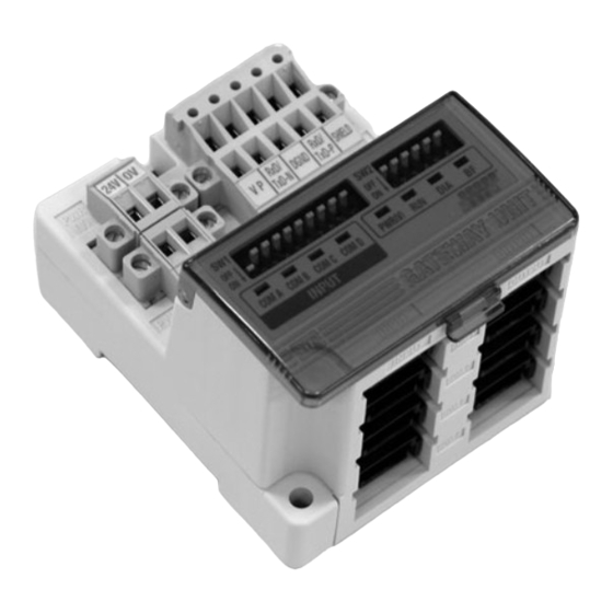
Page 5: Product Summary
Product Summary Name of Parts/ Accessories System structure Accessory Power supply connector ( 2 pcs ) Connecting to bus Valve manifold at upper level with SI unit Power supply ( PROFIBUS-DP ) DC24V connecting to for output 4 sets maximum Power supply DC24V GW unit... -
Page 6: Dimensions
Dimensions (in mm) Settings (continued) Mounted on DIN rail 25.7 Put claw 1 at the body under DIN rail and push it upward. Push down claw 2 to the opposite rail until the claw clicks securely on to rail. (Mounting procedure For removing, lever up the DIN rail fixing plate at the body with a flat screwdriver, and remove it by tilting claw 2 side forward. -
Page 7: Specifications
Specifications Basic specifications Lower level bus Number of branches for 4 branches for input Rated voltage 24VDC input/ output 4 branches for output Power supply for input and controlling GW : Range of 24VDC 10% power supply Communication protocol: Dedicated for SMC Power supply for output : 24VDC+10%/-5% Communication type voltage... - Page 8 Wiring (continued) Branch wiring Press fitting Press the cover to the body with plier etc. The wiring between each unit should use branch cables, and be connected with branch connectors. Confirmation SI unit and Input unit have 2 branch connectors for each. It is completed with a check on 4 latches engaging.
- Page 9 Wiring (continued) Communication wiring The value of terminating resistor changes with cable specification. This value of terminating resistor is based on type A cable (Refer Connect PROFIBUS-DP dedicated cables to the communication to Drawing 3). connector for PROFIBUS-DP. Specification of type A cable (1)Make sure to connect the signal cables to designated pins (Refer to Drawing 1).
-
Page 10: Display/ Switch Setting
Display / Switch Setting Wiring (continued) Power supply wiring Setting for Display Connect power supply wiring to the two power supply 2pin connectors. Power supply structure consists of 2 systems, but it can be used with both single power supply and separate power supply. - Page 11 Display/ Switch Setting (continued) Switch setting UNIT STATUS setting (switch No. 8) Make sure that switch setting is performed with power supply The setting is as follows. turned off. The settings when shipped from plant is turned OFF, GW status The switch setting is mode available by opening a cover and information is not sent to master side as an input data.
-
Page 12: Troubleshooting
Troubleshooting Display/ Switch Setting (continued) Input/Output Setting (SW2) Overall system Input/Output Setting is performed with SW2. Item Remedy / Disposal Number of input setting Number of output setting •Check the power for output (24VDC) is supplied. •Check the branch cable is connected to SI Solenoid unit. - Page 13 Troubleshooting (continued) PROFIBUS-DP compatible communication Item Remedy / Disposal •Check the signal line from PLC is correctly connected. •Check the wiring and pin numbers. •Check the address setting is correct. 1 BF LED lights up •Check the connecting condition of the terminating resistor.
Need help?
Do you have a question about the EX510-GPR1 and is the answer not in the manual?
Questions and answers