SMC Networks EX260 Series Operation Manual
Si unit for cc-link
Hide thumbs
Also See for EX260 Series:
- Operation manual (39 pages) ,
- Operation manual (37 pages) ,
- Operation manual (28 pages)

Related Manuals for SMC Networks EX260 Series


Summary of Contents for SMC Networks EX260 Series
- Page 1 No.EX※※-OMP0005-E PRODUCT NAME SI unit for CC-Link MODEL / Series / Product Number EX260 Series...
-
Page 2: Table Of Contents
Table of Contents Safety Instructions Model Indication and How to Order Summary of Product elements Installation and Wiring Installation Wiring LED Indication and Settings Troubleshooting and Maintenance Specifications Specifications Dimensions Accessories No.EX※※-OMP0005-E... -
Page 3: Safety Instructions
Safety Instructions These safety instructions are intended to prevent hazardous situations and/or equipment damage. These instructions indicate the level of potential hazard with the labels of "Caution", "Warning" or "Danger". They are all important notes for safety and must be followed in addition to International Standards (ISO/IEC) , and other safety regulations. - Page 4 Safety Instructions Caution 1.The product is provided for use in manufacturing industries. The product herein described is basically provided for peaceful use in manufacturing industries. If considering using the product in other industries, consult SMC beforehand and exchange specifications or a contract if necessary. If anything is unclear, contact your nearest sales branch.
- Page 5 Operator This operation manual is intended for those who have knowledge of machinery using pneumatic equipment, and have sufficient knowledge of assembly, operation and maintenance of such equipment. Only those persons are allowed to perform assembly, operation and maintenance. Read and understand this operation manual carefully before assembling, operating or providing maintenance to the product.
- Page 6 ■NOTE ○Follow the instructions given below when designing, selecting and handling the product. The instructions on design and selection (installation, wiring, environment, adjustment, operation, described below must also be followed. maintenance, etc.) Product specifications •When conformity to UL is required, the SI unit should be used with a UL1310 Class 2 power supply. •The SI unit is a UL approved product only if they have a mark on the body.
- Page 7 Product handling Installation •Do not drop, hit or apply excessive shock to the fieldbus system. Otherwise damage to the product can result, causing malfunction. •Tighten to the specified tightening torque. If the tightening torque is exceeded the mounting screws may be broken. IP67 protection cannot be guaranteed if the screws are not tightened to the specified torque.
- Page 8 •Mount the product in a place that is not exposed to vibration or impact. Otherwise failure or malfunction can result. •Do not use the product in an environment that is exposed to temperature cycle. Heat cycles other than ordinary changes in temperature can adversely affect the inside of the product. •Do not expose the product to direct sunlight.
-
Page 9: Model Indication And How To Order
Model Indication and How to Order EX260-SMJ 1 Connector type, output specification M12 connector, 32 outputs, PNP (negative common) / source M12 connector, 32 outputs, NPN (positive common) / sink M12 connector, 16 outputs, PNP (negative common) / source M12 connector, 16 outputs, NPN (positive common) / sink Fieldbus CC-Link No.EX※※-OMP0005-E... -
Page 10: Summary Of Product Elements
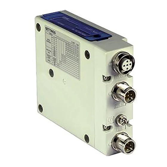
Summary of Product elements <EX260-SMJ1/-SMJ2/-SMJ3/-SMJ4> Element Description 1 Fieldbus interface connector CC-Link connection PORT 2. (BUS OUT) (M12 5-pin socket, A-coded) 1 Fieldbus interface connector CC-Link connection PORT 1. (BUS IN) (M12 4-pin plug, A-coded) 1 Power supply with load voltage for valves and operating voltage for SI unit. Power supply connector (M12 5-pin plug, B-coded) Ground terminal... -
Page 11: Installation And Wiring
Installation and Wiring ■Installation Connect valve manifold to the SI unit. •Dimensions for installation n: number of valve stations 120.7 136.7 152.7 168.7 184.7 200.7 216.7 232.7 248.7 264.7 280.7 296.7 312.7 328.7 344.7 (mm) The above table shows dimensions as an example for the SY5000 series valve manifold. Connectable valve manifolds are the same as for EX250 series SI unit. -
Page 12: Wiring
■Wiring Select the appropriate cables to mate with the connectors mounted on the SI unit. ○Fieldbus interface connector layout BUS OUT: M12 5-pin socket, A-coded Designation Description Shield Communication wire DB Communication wire DG Communication wire DA Unused : Recommended mating M12 4-pin plug, part no. PCA-1567717. (Refer to page 26) BUS IN: M12 4-pin plug, A-coded Designation... - Page 13 ○Terminating resistor The terminating resistor to be connected to the CC-Link network depends on the type of cables used. Please refer to the table below. Cable type Terminating resistor Communication cable for CC-Link Built-in terminating resistor 110 Ω 110 Ω 1/2 W With socket for BUS IN - PCA-1567720 Set the SI unit DIP Switch-No.2 to ON With plug for BUS OUT - PCA-1567717...
- Page 14 ○Power supply connector layout PWR: M12 5-pin plug, B-coded Designation Description SV24 V +24 V for solenoid valve SV0 V 0 V for solenoid valve SI24 V +24 V for SI unit operation SI0 V 0 V for SI unit operation Unused Power-supply line for solenoid valve and power-supply line for SI unit operation are isolated.
- Page 15 ○Ground terminal Connect the ground terminal to ground. Resistance to ground should be 100 ohms or less. -14- No.EX※※-OMP0005-E...
-
Page 16: Led Indication And Settings
LED Indication and Settings ○LED indication LED Status Description Red ON Communication error The station number and baud rate settings have been changed during Red flashing L ERR communication Communication is normal Green ON Communication is normal L RUN Communication has terminated (time out error) Green ON Power supply for SI unit is ON Power supply for SI unit is OFF... - Page 17 ○Switch setting The switches should only be set with the power supply turned off. Open the cover and set the rotary switches and DIP switch with a small flat blade screwdriver. -16- No.EX※※-OMP0005-E...
- Page 18 ○Output information I/O mapping table for master station Buffer Memory. EX260-SMJ□ is a remote I/O station (1 station occupied, 32 inputs/32 outputs). An example of when the SI unit station number is set to 01 is shown below. •I/O memory map of EX260-SMJ1/2 Master station buffer area e.g.: “QJ61BT11N”...
- Page 19 ○Output number assignment Output data : The output numbering refers to the solenoid position on the manifold and starts at zero. : Standard wiring of the manifold is for double-solenoid valves and the output number starts at the A side and then B side in that order as shown in the figure a.
-
Page 20: Troubleshooting And Maintenance
Troubleshooting and Maintenance ○Troubleshooting chart When any malfunction is observed, it is recommended to perform the following troubleshooting. Refer to fault SI unit SI unit No.1 malfunction PWR LED is OFF SI unit Refer to fault PWR (V) LED No.2 is OFF Flashing Refer to fault... - Page 21 Troubleshooting table Fault No.1 Fault Probable cause Recommended error handling Recommended action Re-tighten the power cable. (Replace the cable if it is Defective power Check the condition of the power cable broken) cable wiring for SI wiring to the SI unit. SI unit unit operation Correct the power cable wiring...
- Page 22 Fault No.4 Fault Probable cause Recommended error handling Recommended action Failure of the power Confirm that power is supplied to the master Supply power to the master supply for the station station correctly. master station Check the communication cable is not broken, and that there are no loose connections between the power supply Connect the communication...
- Page 23 Fault No.7 Fault Probable cause Recommended error handling Recommended action Check if solenoid count does not exceed the allowable number. This depends on the SI unit model and valve Group of Keep the number of mounted series. valves not Too many valves solenoid valves within working specification.
- Page 24 ○Maintenance Replacement of the SI unit •Remove the M3 hexagon screws from the SI unit and release the SI unit from the valve manifold. •Replace the SI unit. •Tighten the screws with the specified tightening torque. (0.6 Nm) Precautions for maintenance (1) Be sure to switch off the power.
-
Page 25: Specifications
Specifications ■Specifications General specifications Item Specifications Ambient temperature -10 to +50 Ambient humidity 35 to 85%RH (No condensate) Ambient temperature for storage -20 to +60 Withstand voltage 500 VAC applied for 1 minute Insulation resistance 500 VDC, 10 MΩ or more Operating atmosphere No corrosive gas Enclosure... -
Page 26: Dimensions
■Dimensions •If a fieldwireable connector is used for the power supply connection, and the SI unit is installed directly to a valve manifold, the connector should be 16 mm or less. If the connector is a larger diameter it will interfere with the clamping face. Recommended cables are specified on page 26. -
Page 27: Accessories
Accessories ○Fieldbus interface connector (BUS OUT) (1) Cable with communication connector (SPEEDCON) Part number: PCA-1567717 Item Specifications Pin No. Cable colour: Signal 7.7 mm Cable O.D. : SLD Nominal cross section AWG20 White : DB Yellow: DG Wire diameter 2.55 mm (Including insulator) Blue : DA Min. - Page 28 ○Fieldbus interface connector (BUS IN) (1) Cable with communication connector (SPEEDCON) Part number: PCA-1567720 Item Specifications Pin No. Cable colour: Signal 7.7 mm Cable O.D. : SLD Nominal cross section AWG20 White : DB Yellow: DG Wire diameter 2.55 mm (Including insulator) Blue : DA Min.
- Page 29 ○Power supply connector (1) Cable with power supply connector Part number: EX9-AC0 1 0-1 Cable length (L) 1000 [mm] 3000 [mm] 5000 [mm] Item Specifications Pin No. Cable colour: Signal 6.4 mm Cable O.D. Brown: 24 VDC (For solenoid valve) Nominal cross section AWG22 White : 0 V (For solenoid valve)
- Page 30 ○Seal cap For M12 connector socket: 10 pcs. Part number: EX9-AWTS This cap is used to protect the M12 connector opening when the connector is not used. When the "BUS OUT" connector is not used, the seal cap can keep the SI unit under IP67 rated protection.
- Page 31 Revision history A: Addition of accessories. B: Modified errors in text. C: Limited warranty and Disclaimer are added. D: Modified errors in text. E: Contents are added. Note: Specifications are subject to change without prior notice and any obligation on the part of the manufacturer. ©...
Need help?
Do you have a question about the EX260 Series and is the answer not in the manual?
Questions and answers