SMC Networks EX260 Series Operation Manual
Si unit for ethernet/ip
Hide thumbs
Also See for EX260 Series:
- Operation manual (39 pages) ,
- Operation manual (1 page) ,
- Operation manual (28 pages)
Advertisement
Advertisement
Table of Contents

Related Manuals for SMC Networks EX260 Series


Summary of Contents for SMC Networks EX260 Series
- Page 1 No.EX##-OMP0013-A PRODUCT NAME SI unit for EtherNet/IP MODEL / Series / Product Number EX260 Series...
-
Page 2: Table Of Contents
Table of Contents Safety Instructions Model Indication and How to Order Summary of Product elements Installation and Wiring Installation Wiring LED Indication and Settings Hardware configuration EDS file and icon Setting using RSLogix5000 Setting using Network Configuration Troubleshooting and Maintenance Specifications Specifications Dimensions... -
Page 3: Safety Instructions
Safety Instructions These safety instructions are intended to prevent hazardous situations and/or equipment damage. These instructions indicate the level of potential hazard with the labels of "Caution", "Warning" or "Danger". They are all important notes for safety and must be followed in addition to International ∗... - Page 4 Caution The product is provided for use in manufacturing industries. The product herein described is basically provided for peaceful use in manufacturing industries. If considering using the product in other industries, consult SMC beforehand and exchange specifications or a contract if necessary. If anything is unclear, contact your nearest sales branch.
- Page 5 Operator ♦This operation manual is intended for those who have knowledge of machinery using pneumatic equipment, and have sufficient knowledge of assembly, operation and maintenance of such equipment. Only those persons are allowed to perform assembly, operation and maintenance. ♦Read and understand this operation manual carefully before assembling, operating or providing maintenance to the product.
- Page 6 ■NOTE ○Follow the instructions given below when designing, selecting and handling the product. •The instructions on design and selection (installation, wiring, environment, adjustment, operation, described below must also be followed. maintenance, etc.) ∗Product specifications •When conformity to UL is required, the SI unit should be used with a UL1310 Class 2 power supply. •The SI unit is a approved product only if they have a mark on the body.
- Page 7 •Product handling ∗Installation •Do not drop, hit or apply excessive shock to the fieldbus system. Otherwise damage to the product can result, causing malfunction. •Tighten to the specified tightening torque. If the tightening torque is exceeded the mounting screws may be broken. IP67 protection cannot be guaranteed if the screws are not tightened to the specified torque.
- Page 8 •Mount the product in a place that is not exposed to vibration or impact. Otherwise failure or malfunction can result. •Do not use the product in an environment that is exposed to temperature cycle. Heat cycles other than ordinary changes in temperature can adversely affect the inside of the product. •Do not expose the product to direct sunlight.
-
Page 9: Model Indication And How To Order
Model Indication and How to Order EX260-SEN 1 Connector type, output specification M12 connector, 32 outputs, PNP (negative common) / source M12 connector, 32 outputs, NPN (positive common) / sink M12 connector, 16 outputs, PNP (negative common) / source M12 connector, 16 outputs, NPN (positive common) / sink Fieldbus EtherNet/IP ... -
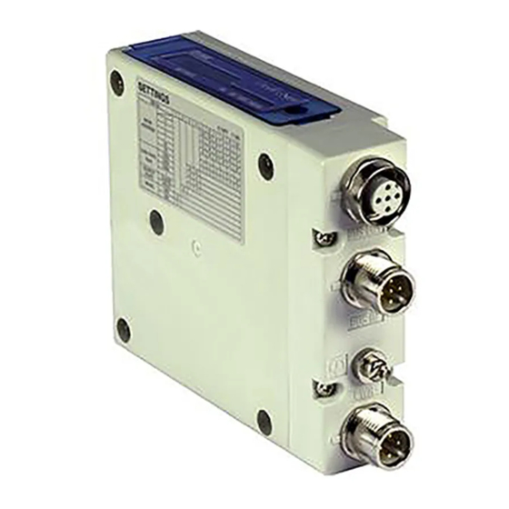
Page 10: Summary Of Product Elements
Summary of Product elements <EX260-SEN1/-SEN2/-SEN3/-SEN4> Element Description ∗ 1 Fieldbus interface connector EtherNet/IP connection PORT 2. (BUS OUT) (M12 4-pin socket, D-coded) ∗ 1 Fieldbus interface connector EtherNet/IP connection PORT 1. (BUS IN) (M12 4-pin socket, D-coded) ∗ 1 Power supply with load voltage for valves and operating voltage for SI unit. Power supply connector (M12 4-pin plug, A-coded) Ground terminal... -
Page 11: Installation And Wiring
Installation and Wiring ■Installation Connect valve manifold to the SI unit. •Dimensions for installation n: number of valve stations 120.7 136.7 152.7 168.7 184.7 200.7 216.7 232.7 248.7 264.7 280.7 296.7 312.7 328.7 344.7 (mm) The above table shows dimensions as an example for the SY5000 series valve manifold. Connectable valve manifolds are the same as for EX250 series SI unit. -
Page 12: Wiring
■Wiring Select the appropriate cables to mate with the connectors mounted on the SI unit. ○Fieldbus interface connector layout BUS OUT: M12 4-pin socket, D-coded Designation Description Transmit Data + Receive Data + Transmit Data - Receive Data - BUS IN: M12 4-pin socket, D-coded Designation Description Transmit Data +... - Page 13 ○Power supply connector layout PWR: M12 4-pin plug, A-coded Designation Description SI24 V +24 V for SI unit operation SV24 V +24 V for solenoid valve SI0 V 0 V for SI unit operation SV0 V 0 V for solenoid valve Power-supply line for solenoid valve and power-supply line for SI unit operation are isolated.
- Page 14 ○Ground terminal Connect the ground terminal to ground. Resistance to ground should be 100 ohms or less. -13- No.EX##-OMP0013-A...
-
Page 15: Led Indication And Settings
LED Indication and Settings ○LED indication LED Status Description The SI unit operating voltage is not supplied or the IP address is not set. Green ON EtherNet/IP communications established. Green flashing EtherNet/IP communications not established. Red flashing EtherNet/IP communications time out. Red ON IP address duplicated. - Page 16 ○Switch setting The switches should only be set with the power supply turned off. Open the cover and set the rotary switches and DIP switch with a small flat blade screwdriver. -15- No.EX##-OMP0013-A...
- Page 17 ∗1: Remote control (IP Address X switch set to 000) The mode to respond to the following commands of the BOOTP/DHCP Server, supplied by Rockwell Automation. Enable DHCP The IP address etc. can be obtained from the BOOTP/DHCP Server. If the power supply is switched off and on again in this state, the SI unit will obtain the IP address etc.
-
Page 18: Hardware Configuration
Hardware configuration ■EDS file and icon The compatible EDS file is required to configure the SI unit within an EtherNet/IP network. Please download the latest EDS file from the following URL (http://www.smcworld.com). ∗: The method of installing the EDS file depends on the configuration software, so please refer to the configuration software manual. EDS file ... - Page 19 •The Select Module Type screen will be displayed. Select [ETHERNET MODULE Generic Ethernet Module] and click on OK. -18- No.EX##-OMP0013-A...
- Page 20 •The Module Properties screen will be displayed. Perform the various settings. (1) Name: Input a unit name of your choice. (2) Comm Format: Select the data format of the Connection Parameters. (3) IP Address: Input the IP Address of the SI unit. (4) Assembly Instance: Set as follows: Input = 100...
-
Page 21: Setting Using Network Configuration
■Setting using Network Configurator The method of connecting the SI unit with an Omron EtherNet/IP (master) module is shown below. Refer to the Network Configurator manual for further details. ∗: The screens shown below are based on using the Omron Network Configurator software. - Page 22 •Double-click on the icon of the master to open the Edit Device Parameters window, and move the SI unit from the [Unregister Device List] to the [Register Device List]. -21- No.EX##-OMP0013-A...
- Page 23 •Double click on the SI unit in the [Register Device List] to open the Edit Connection screen. For [Connection I/O Type], select [Exclusive Owner]. For the Originator Device, select an arbitrary [Input Tag Set] and [Output Tag Set], with the same number of bytes as the [Output Tag Set] and [Input Tag Set] in the Target Device, and register the Input / Output connections.
- Page 24 Example: Tag Set D00100 (2 bytes) to the Input, and D00150 (4 bytes) to the Output. -23- No.EX##-OMP0013-A...
- Page 25 •If the allocation has been correctly completed, the registered IP address will be displayed with the SI unit icon in the network window. -24- No.EX##-OMP0013-A...
- Page 26 ○Output number assignment Output data ∗: The output numbering refers to the solenoid position on the manifold and starts at zero. ∗: Standard wiring of the manifold is for double-solenoid valves and the output number starts at the A side and then B side in that order as shown in the figure a.
-
Page 27: Troubleshooting And Maintenance
Troubleshooting and Maintenance ○Troubleshooting chart When any malfunction is observed, it is recommended to perform the following troubleshooting. Refer to fault SI unit SI unit MS LED is No.1 malfunction Refer to fault SI unit PWR(V) LED No.2 is OFF Refer to fault SI unit L/A LED is... - Page 28 Troubleshooting table Fault No.1 Fault Probable cause Recommended error handling Recommended action Re-tighten the power cable. (Replace the cable if it is Defective power Check the condition of the power cable SI unit broken) cable wiring for SI wiring to the SI unit. MS LED is unit operation Correct the power cable wiring...
- Page 29 Fault No.6 Fault Probable cause Recommended error handling Recommended action SI unit Parameter setting Contact your nearest SMC MS LED is error Sales Office. green flashing Fault No.7 Fault Probable cause Recommended error handling Recommended action SI unit NS LED is IP address has not Check the IP address setting.
- Page 30 Fault No.12 Fault Probable cause Recommended error handling Recommended action Tighten the screws with the Poor connection Check if there are any loose screws making specified tightening torque between SI unit and the connection between the SI unit and the (i.e.
- Page 31 ○Maintenance Replacement of the SI unit •Remove the M3 hexagon screws from the SI unit and release the SI unit from the valve manifold. •Replace the SI unit. •Tighten the screws with the specified tightening torque. (0.6 Nm) Precautions for maintenance (1) Be sure to switch off the power.
-
Page 32: Specifications
Specifications ■Specifications General specifications Item Specifications Ambient temperature -10 to +50 Ambient humidity 35 to 85%RH (No condensate) Ambient temperature for storage -20 to +60 Withstand voltage 500 VAC applied for 1 minute Insulation resistance 500 VDC, 10 MΩ or more Operating atmosphere No corrosive gas Pollution degree... - Page 33 Communication specifications Item Specifications Protocol Ethernet (IEEE802.3) Standard Ethernet cable (CAT5 or more) Transmission medium (100BASE-TX) Transmission speed 10 Mbps / 100 Mbps (Auto negotiation) Transmission method Full duplex / Half duplex (Auto negotiation) EtherNet/IP Fieldbus protocol Volume1 (Edition 3.8) Volume2 (Edition 1.9) Vendor ID 7h (SMC Corporation)
- Page 34 ○I/O Mapping Input area mapping Input data Offset (Word) SOLV L: Low fixed (0) Input status area Input status area specifications Item Status State Normal SOLV State of power supply for solenoid valve Abnormal (19 V or less) Output area mapping •For EX260-SEN1/-SEN2 Output data Offset...
-
Page 35: Dimensions
■Dimensions •If a fieldwireable connector is used for the power supply connection, and the SI unit is installed directly to a valve manifold, the connector should be φ16 mm or less. If the connector is a larger diameter it will interfere with the clamping face. Recommended cables are specified in the accessories section, on page 35. -
Page 36: Accessories
Accessories ○Connector cable Suitable connector SI unit connector Description Part number Specifications Manufacturer EX9-AC010EN-PSRJ: 1 m EX9-AC020EN-PSRJ: 2 m Connector: M12 straight at EX9-AC030EN-PSRJ: 3 m one end and RJ45 Cable with EX9-AC050EN-PSRJ: 5 m at the other end communication Fieldbus EX9-AC100EN-PSRJ: 10 m connector... - Page 37 Revision history A: Modified errors in text. Note: Specifications are subject to change without prior notice and any obligation on the part of the manufacturer. EtherNet/IP is a trademark of ODVA. © 2012 SMC Corporation All Rights Reserved ...
Need help?
Do you have a question about the EX260 Series and is the answer not in the manual?
Questions and answers